Hi all.
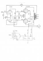
I built a single channel push pull amp from the Dynaco 10W schematic found everywhere.

Also used some simple 15W output transformers designed for guitar amps without UL taps so had to run a SG resistor off B+. That OT claimed primary impedance 8k and output 4ohm. My speakers say 6ohm.
I fed B+ with 300V and the thing sounded fantastic as per that schematic.
I can't remember what the value was but I fed the EL84 screens with b+ across a resistor.
So now I am in a position where I want to build a stereo version of this amp and in a chassis rather than just bread boarding. I have a few questions.
The power transformer I want to use is the Hammond 260E.
260E 80VA 450V C.T. @ 115ma. 5V @ 2A 6.3V C.T. @ 3A
The 6.3vAC tap should be sufficient to run the EL84 heaters and I plan to rectify the 5VAC into DC which through the solid state rectifier should come out at 6.3VDC? Throw a cap across that and send it straight to the 12AX7 heaters?
Below a sketch of what I am thinking. Any comments in addition to what I have mentioned above also welcome.

I built a single channel push pull amp from the Dynaco 10W schematic found everywhere.
Also used some simple 15W output transformers designed for guitar amps without UL taps so had to run a SG resistor off B+. That OT claimed primary impedance 8k and output 4ohm. My speakers say 6ohm.
I fed B+ with 300V and the thing sounded fantastic as per that schematic.
I can't remember what the value was but I fed the EL84 screens with b+ across a resistor.
So now I am in a position where I want to build a stereo version of this amp and in a chassis rather than just bread boarding. I have a few questions.
- I want to feed the screens with B+ across a resistance, do you think the 100ohm is sufficient in this case?
- 1W in that position or should I be going 5W?
- I've dropped the resistor feeding the 12AX7s. This is of course because I will be feeding 2x 12AX7s so the increase in current meant I needed to decrease the resistance but I went further to increase the voltage going to them. Is this too much now? I was hoping it may increase my clean volume.
- Should I also drop the resistance of the 100ohm 10W resistor and use a 20W+ resistor in this position as it is now feed both amps? Unless I separated the feed from the rectifier into two power filter boards, one for each side of the amp?
The power transformer I want to use is the Hammond 260E.
260E 80VA 450V C.T. @ 115ma. 5V @ 2A 6.3V C.T. @ 3A
The 6.3vAC tap should be sufficient to run the EL84 heaters and I plan to rectify the 5VAC into DC which through the solid state rectifier should come out at 6.3VDC? Throw a cap across that and send it straight to the 12AX7 heaters?
Below a sketch of what I am thinking. Any comments in addition to what I have mentioned above also welcome.
Just a general comment on the Hammond 260E. It is not suitable for a stereo version.
You will need 160mA for a minimum HT current. Assume 35-40mA per valve and add a bit.
The heater current would be marginal too. Far better to over specify and run cool.
You have a confused drawing of the power supply. You have draw it with a bridge rectifier, you only need two diodes, one in each 'arm' of the transformer secondary. As drawn you will get smoke pretty quickly...
Alan
Do this
Attachments
In full pentode mode, the screen grid has to be at the same AC potential as the cathode. Caps. bypassing those g2 resistors to ground are needed.
Bridge rectifying the 450 VAC end to end is going to get you a roughly 610 V. B+ rail. 😡 That's very bad. You need to use 2X 1000 PIV diodes in a full wave center tapped (FWCT) configuration to produce a B+ rail in the 300 V. range.
Maximum open loop linearity in full pentode mode is achieved by regulating g2 B+ at a fraction of anode B+.
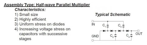
Take no prisoners, when setting up the 12AX7 DC heater supply. A 3 stage 1/2 wave parallel voltage multiplier, energized by 5 VAC, feeding a 7812 3 terminal regulator does exactly that. 300 mA. of 12 VDC takes care of 2X 12AX7s and that should not be problematic. Don't worry about 12 V. vs. 12.6 V., as it is well within tolerances.
The appropriate value of the phase compensation cap. bypassing the 1 Kohm NFB resistor is tied directly to the characteristics of the specific O/P trafo being used. The correct value for the cap. is determined experimentally by feeding a 2 KHz. square wave into the amp and tweaking things to get the best looking product at the speaker terminals, using an Oscilloscope. Let us know if you don't have the requisite O'scope and signal generator. In that event, we'll discuss your options.
Bridge rectifying the 450 VAC end to end is going to get you a roughly 610 V. B+ rail. 😡 That's very bad. You need to use 2X 1000 PIV diodes in a full wave center tapped (FWCT) configuration to produce a B+ rail in the 300 V. range.
Maximum open loop linearity in full pentode mode is achieved by regulating g2 B+ at a fraction of anode B+.
Take no prisoners, when setting up the 12AX7 DC heater supply. A 3 stage 1/2 wave parallel voltage multiplier, energized by 5 VAC, feeding a 7812 3 terminal regulator does exactly that. 300 mA. of 12 VDC takes care of 2X 12AX7s and that should not be problematic. Don't worry about 12 V. vs. 12.6 V., as it is well within tolerances.
The appropriate value of the phase compensation cap. bypassing the 1 Kohm NFB resistor is tied directly to the characteristics of the specific O/P trafo being used. The correct value for the cap. is determined experimentally by feeding a 2 KHz. square wave into the amp and tweaking things to get the best looking product at the speaker terminals, using an Oscilloscope. Let us know if you don't have the requisite O'scope and signal generator. In that event, we'll discuss your options.
Attachments
An actual transformer copied from the dynaco pattern is available from Triode USA Tube Amp Kits Transformers Tubes Dynaco Upgrades and Parts
I believe product was called SC35.
I would say guitar transformers are suitable for reproducing 200-7000 hz. Same upper limit on organ transformers, although they may be suitable down to 32 hz. My ears still hear 14 khz, and many classical and pop media sources have instruments that produce these frequencies. Top octave piano, cymbals, tinkly bells sound very strange with the high frequencies cut off.
Last edited:
In my opinion the circuit used in the st-35 is much better with the same parts count
( one 7247/ECC823 and 2 EL84) in a stereo amp it could be realized with 1 ECC83 one
ECC82 and 2 EL82
( one 7247/ECC823 and 2 EL84) in a stereo amp it could be realized with 1 ECC83 one
ECC82 and 2 EL82
The phase splitter output amplitudes in posts # 1 and # 2 are not perfectly balanced.
Out of phase, yes. Equal amplitudes, no. Equal distortions, no.
Fortunately, the global negative feedback helps to correct for the distortion that type of phase splitter creates.
(If the signals were perfectly balanced there at the output stage control grids, there would not be any signal voltage driving the bottom triode grid of the 12AX7; and that type of splitter requires a signal voltage at that bottom triode grid).
A little resistor tweaking will balance the phase splitter outputs before negative feedback is applied, making one less correction for negative feedback to have to correct.
The less that global negative feedback has to correct, the better.
But even with resistor tweaking, one phase splitter triode will have 2nd harmonic distortion, and the other phase splitter triode will have no 2nd harmonic distortion.
The top triode has it, the bottom triode is working in the opposite direction and so "cancels the 2nd at its output.
Now, you have 2nd harmonic distortion driving the top EL84, and no 2nd harmonic distortion driving the bottom EL84.
Not so good.
Now you know why I prefer a phase splitter with a current sink at the bottom of parallel cathodes.
Many of you call this an LTP, but that so often uses a resistor. The current sink is better, it intrinsically makes the output amplitudes balanced, and also intrinsically cancels the 2nd harmonic in both outputs.
"You should make things as simple as possible, but no simpler" - Albert Einstein
In my opinion the circuit used in the st-35 is much better with the same parts count
( one 7247/ECC823 and 2 EL84) in a stereo amp it could be realized with 1 ECC83 one
ECC82 and 2 EL82
I agree. I understand that the OP has one channel done and would like to add another for stereo, but his current iron appears to be marginal (and the previous poster explained some of the current circuit’s limitations), so why not just chalk up the first amp to learning and “do it right” this time around in the final version? (Unless OP really likes the current amp and want no better.) The Dyna ST35 design (with good iron) has earned its good reputation, so I mention it as one alternative, or the outstanding EL84 Baby Huey below.
1. diytube.com used to make a PCB for its version of a 12AX7/12AU7 ST35 implementation as petertub described above, and it sounded as good or better than the original. Unfortunately, Shannon has stopped operations at diytube some time ago. However, the schematic could be hard-wired. The whole, and very good, construction manual and schematic are here:
http://www.diytube.com/st35/ST35REVE.pdf
2. The latest group buy is currently still open for Baby Huey PCBs (both EL84, EL34 versions and PSU boards). It features exactly the phase splitter favored by the previous poster plus a lot more. Search for Baby Huey on diyaudio and you will find tons of information.
Best wishes in your pursuits.
Last edited:
I think Triode Electronics sells the Diytube ST 35 board. Anyway, I built one years ago and it’s decent. The adjustable bias is a good idea, I’ve used it on other EL84 amps. Check out the diytube link above. The bias circuit is simple, it’s adjustable cathode bias, and a good way to balance the current in the Opt primary for lower distortion.
Stevedores
Stevedores
The Z565 O/P trafo used in the ST35 is a price/performance champion. It works well in any rational design, including (but certainly not limited to) "Baby Huey" and "El Cheapo".
Attachments
Agreed!
Individual bias for each EL84 is a very good idea.
Do that for either method; self bias, and for fixed bias.
Then you can balance the EL84 currents.
Balancing the plate currents to the Z565, does reduce the low frequency harmonic distortion.
And, it also reduces the intermodulation of bass frequencies that otherwise modulates on top of mid and high frequencies.
The better the open loop distortion is, the better the global negative feedback works.
Last edited:
All excellent info and much more than I anticipated. Thanks everyone for your input. I'm not sure I understand everything but so far...
The OTs have to be switched out, that much I knew already. They did sound good but everything I've read has stated OTs are the heart of the amp so I've been eyeing off some others.
I'm going to get to googling all of the above info, see if I can make semse of it and draw the schematic again for further review!
Thanks everyone!
...actually everybody is saying you'll need a different (bigger) power transformer to make stereo. If you want to use 'better' output transformers it may be a good idea, but if you like the way it sounds and you can get another, might as well use what you have! 🙂
Look here for a modestly priced power trafo that has all the "stones" needed for this project. No fussing with a 12AX7 DC heater supply is necessary. 😉
If the cost of Z565 "iron" is too high for the bank balance, consider this Edcor offering. Not as good as the "Dynaclone" stuff, but decent performance at lower cost.
If the cost of Z565 "iron" is too high for the bank balance, consider this Edcor offering. Not as good as the "Dynaclone" stuff, but decent performance at lower cost.
Don,t have the info in front of me at the moment but an Edcor PT, 2x OPTs and a choke can be had for ~ $215 US. Would make a fine stereo EL84 amp.
Steve
Steve
Ok so the message I am getting loud and clear is that if I am going to do this I may as well build the best version of it possible and there doesn't seem to be an enormous difference in price between doing it on the cheap and doing it correctly and in all honesty, the sound I got out of the single channel version I did with the simple circuit and the Guitar Amp OTs sounded like an amp I'd listen to forever so I can justify spending more to go with what is highly recommended.
So I'd like to invite comment on this variant of the ST35 schematic. Full build details linked below and the snapshot of the schematic. This recommends transformers that have already come highly recommended and am happy to spend the money on those or equivalents which come highly recommended. It also means I just need to put one of my 12AX7s on the bench and introduce a 12AU7 which I am happy enough to do unless you think this circuit will work equally as well with 2x 12AX7s?
Is the feeling this circuit may have advantages over the traditional ST35 circuit?
ST35 REVE.pdf - Google Drive
An externally hosted image should be here but it was not working when we last tested it.
Ok so the message I am getting loud and clear is that if I am going to do this I may as well build the best version of it possible and there doesn't seem to be an enormous difference in price between doing it on the cheap and doing it correctly and in all honesty, the sound I got out of the single channel version I did with the simple circuit and the Guitar Amp OTs sounded like an amp I'd listen to forever so I can justify spending more to go with what is highly recommended.
So I'd like to invite comment on this variant of the ST35 schematic. Full build details linked below and the snapshot of the schematic. This recommends transformers that have already come highly recommended and am happy to spend the money on those or equivalents which come highly recommended. It also means I just need to put one of my 12AX7s on the bench and introduce a 12AU7 which I am happy enough to do unless you think this circuit will work equally as well with 2x 12AX7s?
Is the feeling this circuit may have advantages over the traditional ST35 circuit?
ST35 REVE.pdf - Google Drive

This should be fine, however simplifying it to be with a common
fixed cathode resistor ( and elemination the uneeded separate cathode
parts) would enhance this build. Just do it as the st35 is done it's a better way
of doing this. A matched quad of EL84 is needed anyway.
The suggested complicated cathode conntors is NOT an improvement it's
a waste of components.
Last edited:
Hi everyone and thanks so much again for all the info, you are all preventing me making some expensive mistakes!!
I think at this time I want to build the standard ST35 with the mods to the power supply as noted in Dave's Lab and with the individual bias circuits for each el84.
I have 2x 12AX7s at the moment so will need to bench one of these and employ a 12AU7.
I am thinking, to keep thing a bit more cost effective I will be going with the Edcor transformers.
PT 240V, 50/60Hz. line to 660V (330-0-330) at 180mA center tapped and two 6.3V at 2.5A
I have a question about OTs. They have two that look sufficient but have different screen taps. One just says it has screen taps so I am assuming they are 40%? The other says 23% screen taps. Could someone comment and perhaps let me know if one option is more preferable in this case?
My assumption is that the 40% tap would be more appropriate? Both linked below.
23%
EDCOR - CXPP25-8K/23%
And the regular
EDCOR - CXPP25-8K
Also....
With the 12AX7 that won't be used in the driver section - what would stop me building in a preamp section that I can isolate when I do not want to use it and connect when I do want to use it? I think the PT has sufficient power to get it done so seems like a good little addition to a custom build unless I am missing something?
660V CT is to much for a EL84 PP
With a tube rectifier 600V CT and with si-diodes 500V CT is the max.
Unless there is a HTregulator or a choke input filter is used.
I don't like the ST35, bad phase splitter and common cathode resistor 🙁
Better idea, look at this one Philips HF309 Mono End Amplifier
Power consuption 85mA HT and 1,8A heater pro amp.
Mona
Last edited:
I think you should go fot 40% taps. And forget the bias board, you needHi everyone and thanks so much again for all the info, you are all preventing me making some expensive mistakes!!
I think at this time I want to build the standard ST35 with the mods to the power supply as noted in Dave's Lab and with the individual bias circuits for each el84.
I have 2x 12AX7s at the moment so will need to bench one of these and employ a 12AU7.
I am thinking, to keep thing a bit more cost effective I will be going with the Edcor transformers.
PT 240V, 50/60Hz. line to 660V (330-0-330) at 180mA center tapped and two 6.3V at 2.5A
I have a question about OTs. They have two that look sufficient but have different screen taps. One just says it has screen taps so I am assuming they are 40%? The other says 23% screen taps. Could someone comment and perhaps let me know if one option is more preferable in this case?
My assumption is that the 40% tap would be more appropriate? Both linked below.
23%
EDCOR - CXPP25-8K/23%
And the regular
EDCOR - CXPP25-8K
Also....
With the 12AX7 that won't be used in the driver section - what would stop me building in a preamp section that I can isolate when I do not want to use it and connect when I do want to use it? I think the PT has sufficient power to get it done so seems like a good little addition to a custom build unless I am missing something?
a matched quad of EL84 anyway. Also use a common cathode resistor
exactly as ST35.
- Home
- Amplifiers
- Tubes / Valves
- Dynaco EL84 PP variant questions