Hi all, I'm new to the forum so please forgive if I posted in the wrong place or something like that.
I want to build some tube amps (5F1, 5F6A, Steel String Singer & Two Rock JM Sig) and I want to make my own transformer/s. I think I understand the power transformers well enough, but I'm having trouble with understanding the output transformers. I had an idea to make one power transformer that has multiple taps so that I can use it for anything from a 5W 5F1 to a 100W SSS, where the transformer is rated for the VA of the highest one. I have done all of the calculations regarding core area & turns per volt.
But then, regarding output transformers though, I understand that the impedance ratio is the square of the turns ratio (which is equal to the voltage ratio) and that the transformer has no impedance of it's own but simply "reflects" the impedance of the speakers to the tubes and vice versa. I have the impedance ratio (eg. 2K1:4 ohm for the SSS running 4 6L6's) and therefore the turns ratio but does anyone know how to calculate the actual amount of turns? I read that having too few or too many can both cause problems. I'm also not completely sure if the amps are push-pull or single ended.
I will probably be able to find a donor core from an old transformer to use but it'll probably be bigger than necessary, that won't cause any problems will it? It would only cause problems if it was too small right?
Thanks all, and sorry for the LONG post 🙂
You have to determine whether it is PP or SE, since single ended output transformers use a gap.
Some info:
http://www.geofex.com/article_folders/xformer_des/xformer.htm
OPT Design - Wikibooks, open books for an open world
Some info:
http://www.geofex.com/article_folders/xformer_des/xformer.htm
OPT Design - Wikibooks, open books for an open world
Last edited:
OPT_DA can get you going: OPT Calucator
There's a lot of info on Patrick Turners site: output-trans-winding
Winding output transformers is a lot of work and you need to practice.
Don't expect a perfect transformer on your first try.
Guitar amps are less critical because the frequency range of the guitar is fairly limited.
For low frequencies you need many primary turns and a big core, but more turns means more parasitics reducing high frequencies. Layout becomes important.
Thank you very much Parafeed813 & rayma, I'll go through those resources and hopefully I can figure it out then. Also, I'll make sure to try to find out if it's push-pull or single ended, I'm just not sure how to find that out. Once again, thanks for the help.
That's basically like trying to build a race car while being not sure how to get inside a regular one.Also, I'll make sure to try to find out if it's push-pull or single ended, I'm just not sure how to find that out.
5F1 (Champ) is SE, other three are PP.
5F6A (Bassman) will require substantially different OPT than SSS/Two Rock, and not only in terms of power.
Building OPTs is HARD. Buy a ready-made one, you'll waste much less time and money. If you're doing this just out of interest, spend some time studying amp basics first.
TG, thanks for the information. I did also ask Ryan Colgan, a guy who has made these in the past, and he confirmed that the big ones are indeed Push-Pull. There are multiple reasons for me wanting to make my own, if I can manage to figure it out: Firstly, it is a skill that I want to learn. Secondly, and perhaps more importantly, is the economical reason. I live in South Africa, so I have to pay for shipping AND the exchange rate is also working against me, so they would cost me more than double what they would cost someone in America or Britain, which is really an absurd amount of money to spend, in my opinion.
I am currently on my second electronics module (second year electronics engineering) so I'm hoping that, although my knowledge and experience is very limited, I might be able to figure this thing out. Thanks, once more, for the feedback, advice and information, I really appreciate it.
I am currently on my second electronics module (second year electronics engineering) so I'm hoping that, although my knowledge and experience is very limited, I might be able to figure this thing out. Thanks, once more, for the feedback, advice and information, I really appreciate it.
I tried a preliminary calculation using OPT_DA OPT Calculator
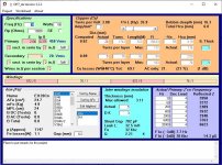
Hi again, I have tried to do a calculation, screenshot attached, any feedback would be greatly appreciated.
I googled the plate resistance of 4 6L6 tubes in 100W Push-Pull and got 10K Ohm, can someone please confirm? Then, I used the primary impedance as 2K1 Ohm and the secondary impedance as 4 Ohm (as per the Classic Tone 40-18013 specs). The plate current, I used as 0.375A (googled, but not quite sure about this). Furthermore, I used 30 Hz as the lowest frequency and 0.2mm gap (also not sure about these)
The "[] sect. in serie by [] in // [split/equal]" & "Wires in // per section []" sections in the top left green box, I have no idea about.
The program said: 1743 turns on the primary (0.28mm diameter wire) & 76 turns on the secondary (0.5mm diameter wire). I checked and these results do get the impedance ratio right. How does this sound, right or wrong?
Once more, thanks all.
Attachments
Looks good but are you sure you can source M6 transformer core? here in México is unobtanium, and is very difficult to import from USA, also if you want a more symetric winding you should divide the primary in 4 parts the inner in series with the outer to have similar DCR , between primary halfs (inner winding will have the lower dcr, the outer one will have the greater) this will reduce the stray field and archieve better coupling between primary and secondary also the DCR will be better balanced between primary halfs that will traduce in lower cooper loss.
You should not spect to use a core gap because its a pushpull transformer by design its supposed that the same or almost the same plate current flowing trough primary halfs, which in the end cancel most of the DC saturation in the core, leaving only AC saturation, if you are planning to have dissimilar DC current or a certain of current imbalance you can put a small gap, but sacrifacing a lot of the primary inductance and low end response.
In reality you should spect something in between 200mA and 250mA biasing for that power if so to speak, that primary gauge seems good, but you can lower it a bit, also make sure your transformer spool have the dimentions the program spects if dont it will very difficult to make fit those windings, and certainly it wont have the same response the program shows.
Last edited:
Thanks so much maton00, you're right, I'll rather use astandard core than M6. Although I'm not sure what the differece is. Also, I don't understand what you mean by split the primary winding in 4, do you mean to have 4 windings of 19 turns each, connected in series, instead of one winding of 76 turns? or do you mean to have 4 windings of 76 turns each in paralell? or some combination of the above or something completely different?
Furthermore, what core size (EI42/EI48/etc.) is best and does having a core that is bigger than specified matter? I ask this because I will probably be using a core from a "donor" transformer as I cannot find anyone locally selling EI laminations.
Thanks a lot.
Furthermore, what core size (EI42/EI48/etc.) is best and does having a core that is bigger than specified matter? I ask this because I will probably be using a core from a "donor" transformer as I cannot find anyone locally selling EI laminations.
Thanks a lot.
Thanks so much maton00, you're right, I'll rather use astandard core than M6. Although I'm not sure what the differece is. Also, I don't understand what you mean by split the primary winding in 4, do you mean to have 4 windings of 19 turns each, connected in series, instead of one winding of 76 turns? or do you mean to have 4 windings of 76 turns each in paralell? or some combination of the above or something completely different?
Furthermore, what core size (EI42/EI48/etc.) is best and does having a core that is bigger than specified matter? I ask this because I will probably be using a core from a "donor" transformer as I cannot find anyone locally selling EI laminations.
Thanks a lot.
Please see by yourself what happens if you choose the lower quality core, and that is the best case scenario in reallity a salvaged core will be inferior at best, I used to make small simple transformers with common transformer laminations, but its a pain to archive a good performance with this cases, at least you will learn a lot, with those you will need to increase to a maximum the turn count, almost as fill as it can be, to get a usable transformer, then you will have problems with copper losses and poor bandwidth.
As a good rule of thumb you will need to get at least 6 times the VA capable core for the output you are willing to get at those frecuencies, so a small lamination like a EI84, EI66 or the like are out of the question, remind you I'm talking of common lower quality laminations (Bsat~1T at best).
By splitting the primary, I was refering to the other winding..... 😱
Haha maton00, I mixed up the primary and secondary, now I understand what you meant, thanks. I'll experiment with core types and sizes to see what works and I'll also ask around and see if I can find any laminations for sale somewhere.
Is this a cost or regulatory issue?is very difficult to import from USA
> I googled the plate resistance of 4 6L6 tubes in 100W Push-Pull and got 10K Ohm
No.
Four 6L6 @100W is "100 Watt Fender". Standard impedance is 2Kct.
http://www.classictone.net/40-18013.pdf
No.
Four 6L6 @100W is "100 Watt Fender". Standard impedance is 2Kct.
http://www.classictone.net/40-18013.pdf
2K is OPT's impedance, not the plate resistance.> I googled the plate resistance of 4 6L6 tubes in 100W Push-Pull and got 10K Ohm
No.
Four 6L6 @100W is "100 Watt Fender". Standard impedance is 2Kct.
Still the plate resistance is not 10K - rather around 40-50K at low levels and heaven knows what at max power.
Last edited:
Is this a cost or regulatory issue?
Is about shipping, and taxes, and then the local taxes is the drop that fills the glass, then you have Edcor and hammond (direct audio OPT suppliers) between those two the ones that are most atractive is hammond even when they are from canada, god knows why, but Edcor is very hard with non US clients, at those shipping and taxes fees, you can get transformers from Toroidy from Poland and get spare change money for a good drink.😕
I have a PPP 6L6 and the OT is a the effective primary plate-to-plate
impedance of the four windings (when normalized to a conventional dual primary
winding transformer) is 2582Ω.
impedance of the four windings (when normalized to a conventional dual primary
winding transformer) is 2582Ω.
I have a PPP 6L6 and the OT is a the effective primary plate-to-plate
impedance of the four windings (when normalized to a conventional dual primary
winding transformer) is 2582Ω.
Thanks Brice, I changed Rp from 10000 Ohm to 2582 Ohm in the program and the number of turns stays the same. In fact pretty much nothing changes, which I find weird, so I guess that doesn't matter much?
Then, on the matter of core size, shape and type. I'll try to find a donor transformer that's at least as big (or bigger) as the Classic Tone 40-18013, that should work well then, right
Also, maton00, I feel you man, importing is a massive pain in the ***. Especially since the US is all the way across the atlantic ocean from SA, you can easily end up paying more for the shipping than for the product.
Nope you are still confusing terms one is tube plate impedance and the other is the transformer impedance, the tube has this internal impedance that is in function of the type of tube, interelectrode distances and emission, the other is for the transformer that is in function of the frequency, inductance, stray capacitances DCR of the wire etc.Thanks Brice, I changed Rp from 10000 Ohm to 2582 Ohm in the program and the number of turns stays the same. In fact pretty much nothing changes, which I find weird, so I guess that doesn't matter much?
Then, on the matter of core size, shape and type. I'll try to find a donor transformer that's at least as big (or bigger) as the Classic Tone 40-18013, that should work well then, right
Also, maton00, I feel you man, importing is a massive pain in the ***. Especially since the US is all the way across the atlantic ocean from SA, you can easily end up paying more for the shipping than for the product.
A tetrode/pentode like the one you use, commonly have like 10-50 Kohms of internal impedance when operating, but those are elements are not very linear, like any active device, its internal impedance will go up and down in function with the power frequency and current trough the element, the transformer will do also but these are passive components so they will be more linear in that regard, and when properly designed, the plate impedance (a normalized one) of the tube is used by the program to estimate the whole at some frequencies of interest (tubes coupled to the transformer) obviusly to a degree because it can vary a lot, since there are a lot of topologies and it isnt consideraring any type of feedback.
This frequencies can be used to see by the user if the transformer will have problems within the audio band, and also if it will need to adjust the whole, more turns, less turns, wire loses, distances within windings (isolation thickness) how it influences the stray capacitances, magnetic coupling ,etc
Hum something is wrong. If you change the primary PP impedance of an OT, this will change everything.
Have you try SOWTER AUDIO TRANSFORMERS WORLDWIDE SHIPPING ?
They can help you with custom solution too. No idea of the shipping cost from there.
Have you try SOWTER AUDIO TRANSFORMERS WORLDWIDE SHIPPING ?
They can help you with custom solution too. No idea of the shipping cost from there.
Thanks again maton00 and Brice, I think I understand a little better now. My calculations and the calculations from OPT_da seem correct to me at this point. This then only leaves winding and testing/experimenting. I had a look at Sowter Transformers and their prices are about the same as/a bit higher than Classic Tone's with shipping.
Does anyone know of any other calculators like OPT_da that can calculate power transformers?
Does anyone know of any other calculators like OPT_da that can calculate power transformers?
- Home
- Amplifiers
- Tubes / Valves
- Diy 100W Tube Amp Output Transformer