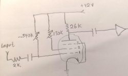
The Little Bear B4-x is nice sounding tube hybrid headphone amp. It's powered by a 12V battery with 2 DC-DC converter (Mornsun A1212S) into +/- 12V for each channel. It uses two of the 5899 subminiture tube and I traced out the tube circuit but my knowledge is far too basic to understand this particular pentode design. Since I like the sound of the amp, I would like to see if I can improve it further by upping the voltage to either 24v or 60V using addition DC converter. But what change should I made to it?
Attachments
Last edited:
I wonder if and how it works very well with positive voltage on the control grid (from the 340k resistor).
But as you increase the B+ to 24V or 60V, you will get even more positive control grid voltage, and lots of current on that grid.
And, you will get different harmonic and intermodulation signatures than you get with +12V.
You may or may not like the 'new' sound.
Is that 5899 followed by a solid state amp (the trapezoid shown in your schematic)?
It seems the original amplifier design attempt was to get tube sound out of a solid state headphone amp, yes or no?
I do not think the 5899 was really made for +12 V operation, but even if it was, I believe the designer may have
tweeked on things until it achieved the desired 'sound'.
What would be interesting would be to see the harmonic distortion signature of the amp, and the intermodulation distortion signature of the amp.
Do you have a clean signal generator, and an oscilloscope that has an FFT function?
If you are going to re-design the amp, and you like the sound of the amp, you need to get those harmonic and intermodulation signatures first, or you may not be able to 'tweek' until you get the same sound you like.
Are you wanting more voltage on the tube because you want more gain from the amp?
Are you wanting more voltage on the tube because you want more power output from the amp?
Those two things are not the same; you will not get more power than the next stage (trapezoid symbol) can produce, unless the Gain of the amp is so low that your signal source can not driver the amp to full power.
Last edited:
Nearly posted something similar.
Isn't the schematic missing a cathode resistor?
Or is this relying on grid leak bias? Although it's also missing that resistor...
I can't see how this works at all.
Saying that, my first pentode circuit I got pin out confused and wound up driving the tube via (I think screen grid) whilst I commoned the 2nd anode and cathode together....
I realised my error, but somehow the circuit made some output and survived.
Last edited:
It is *designed* (or tinkered) to "work" at 12 Volt supply.
At such low plate voltage, the tube tends to cut-off. A high-value resistor G1 to a +positive+ voltage overcomes that fault. In turn it gives low input impedance, but at these voltages and with modern solid-state preamps (or DACs/cellphones) the impedance is acceptable.
If a higher supply voltage is acceptable, stop fooling with this hack and build a proper tube amp.
PRR,
Yes, instead of that circuit, build a real (and good) tube amp.
At those operating conditions the input capacitor is going to charge up with signal applied. And the amount of grid bias voltage is a condition of the signal amplitude. It may even cause blocking.
And the grid will 'see' a driving impedance of at least 2k Ohms, even with a Zero Ohm signal source.
I bet the 2nd Harmonic and 2nd order Intermodulation products are quite high.
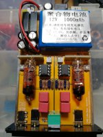
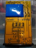
Here are some image of the inside. The tube outputs to a coupling cap and a 100k resistor to ground before a dual opamp (connected as parallel buffer) .
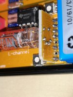
The pin 2, 4 and snip off (both K,g3) and the 8th pin which is also a K,g3 ties to ground.
Both tube heaters are connect in series to the 12V battery where one tube gets a lower 5.78V and the other heater 6.12V. The lower heater tube at grid 1 measured +0.13V while the higher one is -0.18V with respect to ground.
Plate voltage at 6.5V, g2 6.08V.
Just replacing the opamp to opa1612 and add a decoupling cap across the opamp +/-V improves the sound. But I want to see how far I can push the tube to get a better sound and hopefully learn something in the process. The fact that this is a battery powered tube is very intriguing to me. Even if I also have a working Korg nutube board and another 12au7 irf630 hybrid working with 24V.
The headphone amp 5899/opamp combo sound better than the nutube/opa551 board. While the 12au7 sounded warmer but not as spacious and detail as the 5899/opamp.
Attachments
Apply a loud volume signal (steady music or a test tone) at the input, and then re-measure the input grid voltage with the signal present.
Just checked, having a large signal at grid 1 does not affect the grid voltage.
When you tested the grid voltage with a large signal present, where was the 340k input resistor turned to? How many Ohms?
What kind of DC meter are you using?
A DMM,
or A VOM (what was the volt full scale setting?; and what is the VOM sensitivity? (1k/volt, 20k/volt, etc.)?
What kind of DC meter are you using?
A DMM,
or A VOM (what was the volt full scale setting?; and what is the VOM sensitivity? (1k/volt, 20k/volt, etc.)?
Last edited:
So this is a fairly normal (apart from being miniature) pentode used in an unusual circuit in order to get some FX from a 12V supply rail. To "improve" the sound you would first have to establish exactly what it is about the sound that you like; a genuine improvement to the circuit might destroy the very thing you enjoy.
...I want to see how far I can push the tube to get a better sound....
I had an "ART Tube Channel", "tube preamp EQ limiter". One tube and a square yard of chips, of course. I thought it was mushy. Without a schematic, I started jumpering circuit blocks. Intuition led to a configuration which sounded sparkly transparent and clean. Powered-down to put it in the rack, powered-up, and noted that sound came up "instantly", no 11 second tube warm-up. I had bypassed the tube!
In that application (documentary recording of live classical music) I did not want any "flavor". While ART had done the tube-stage well, and I don't have keen ears, it was just enough "mush" to notice, and object to.
Yes, at home I have beat the snot out of tubes and grooved on it.
So this is a fairly normal (apart from being miniature) pentode used in an unusual circuit in order to get some FX from a 12V supply rail. To "improve" the sound you would first have to establish exactly what it is about the sound that you like; a genuine improvement to the circuit might destroy the very thing you enjoy.
For one, working with 12V, is 26K anode best value. And since g1 & g2 has trimmer tie to 12V. What voltage should I be aiming for at the anode, g1, g2.
Hello! I too am interested in this little amp and a bit of modding...now the tube is an 8 pin..buy only 6 used? I would like to tube roll and found some subminiature sockets
Id like to solder thess in position so then obviously easier to swap out tube..here is a link...Mhdt Subminiature Tube Socket B8D
So theoretically..i could just cut off the extra pins on the socket and then solder in to place? I have a burson op on the way and will also mess with some caps etc..
Id like to solder thess in position so then obviously easier to swap out tube..here is a link...Mhdt Subminiature Tube Socket B8D
So theoretically..i could just cut off the extra pins on the socket and then solder in to place? I have a burson op on the way and will also mess with some caps etc..
Here are some image of the inside. The tube outputs to a coupling cap and a 100k resistor to ground before a dual opamp (connected as parallel buffer) .
The pin 2, 4 and snip off (both K,g3) and the 8th pin which is also a K,g3 ties to ground.
Both tube heaters are connect in series to the 12V battery where one tube gets a lower 5.78V and the other heater 6.12V. The lower heater tube at grid 1 measured +0.13V while the higher one is -0.18V with respect to ground.
Plate voltage at 6.5V, g2 6.08V.
Just replacing the opamp to opa1612 and add a decoupling cap across the opamp +/-V improves the sound. But I want to see how far I can push the tube to get a better sound and hopefully learn something in the process. The fact that this is a battery powered tube is very intriguing to me. Even if I also have a working Korg nutube board and another 12au7 irf630 hybrid working with 24V.
The headphone amp 5899/opamp combo sound better than the nutube/opa551 board. While the 12au7 sounded warmer but not as spacious and detail as the 5899/opamp.
Hello @ChuckT - Did you determine the optimum settings for the adjustable pots, connected to Tube Pins 1 (g1 Control Grid) and 7 (g2 Screen Grid)? Is there a specific voltage that should be set on each tube, to provide the lowest distortion, and best matched sound, from the two tubes?
Thanks,
David Baldock
- Status
- This old topic is closed. If you want to reopen this topic, contact a moderator using the "Report Post" button.
- Home
- Amplifiers
- Tubes / Valves
- 5899 pentode circuit in Little Bear B4