Exploring Purifi Woofer Speaker Builds
A thread for discussion on all purifi driver builds.
A place to brainstorm and speculate on drivers and potential speaker builds for arguably, objectively, the best no-nonsense engineering-first traditional speaker drivers' money can buy - If you have a complete project underway, please start your own thread and post a link to it in here. Otherwise posting occasional random progress pics and info here is fine but we will keep full build discussion elsewhere.
We are also pleased to have @lrisbo of purifi occasionally check in and post here of which is much appreciated.
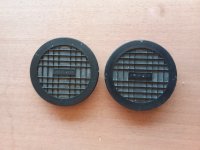
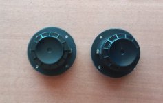
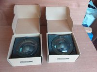
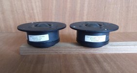
A tweeter is on the way 🤓
Updated 26/01/23: Added more build links and intro - (I may stop updating commercial builds moving forward as they are now coming in thick and fast)
Updated 16/06/22: Added builds and review links, updates to builds
Update 17/03/22: below
Time for a bit of consolidation due to this thread getting some hits, and purifi has now released quite a few scrunchy woofers
Links to known projects & commercial speakers using the Purifi drivers (please PM me if I need to add any)
Of course - www.purifi-audio.com , and the team behind the drivers here
Full DIY:
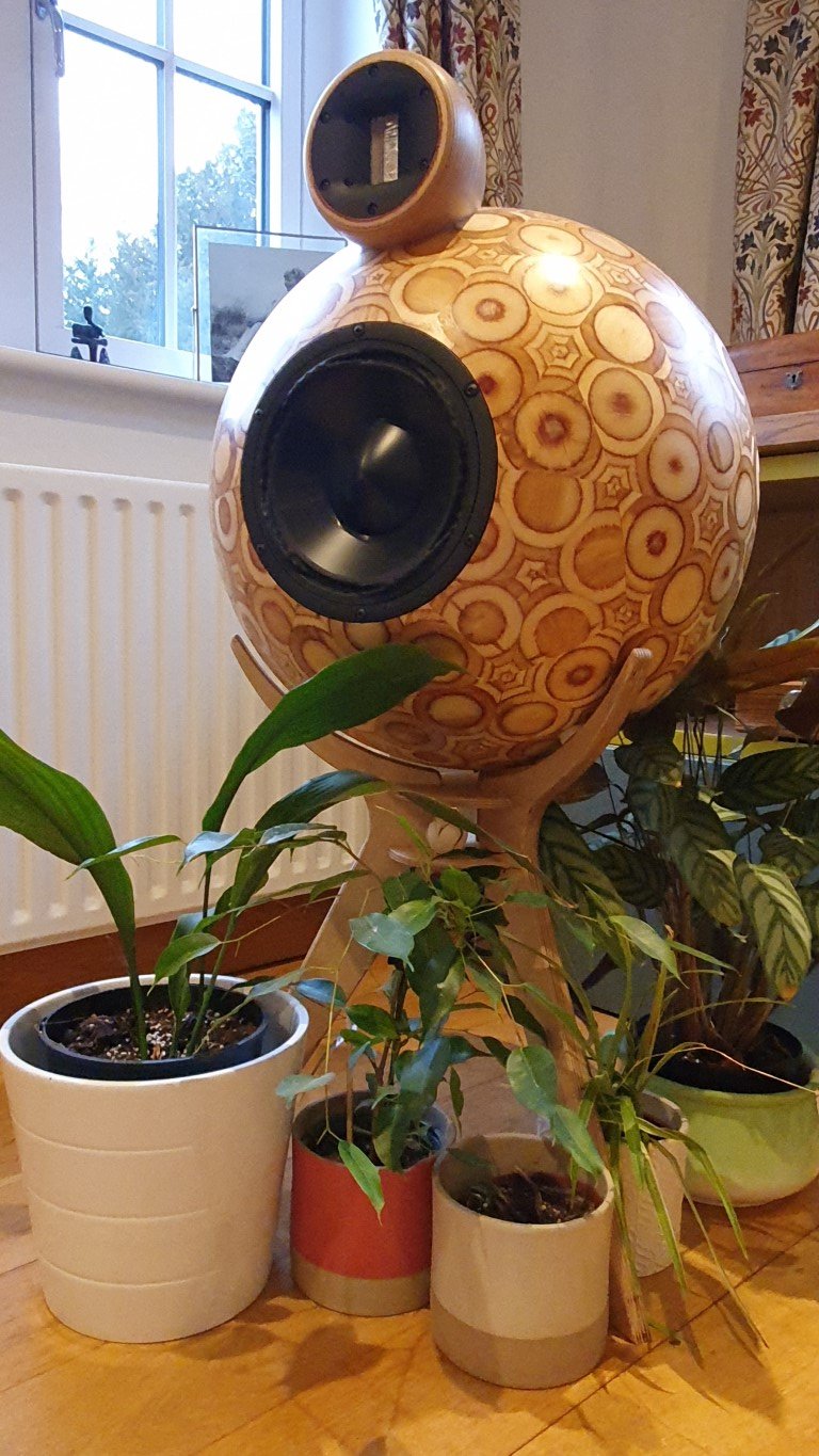
DIYA user @spresto9 has come up with these beauties with the 8" purifi woofer like to details and more pics HERE
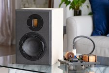
Check out this 4" pocket rocket proof of concept build from the Purifi team - all the info you need to DIY!
Spk8 appnote download (.pdf)

@lrisbo Proof of concept Purifi SPK4 (superseded) - Passive stand-mount

@lrisbo Proof of concept Purifi SPK5 - Passive stand-mount - I believe these were at some point being made and sold commercially but have since been discontinued - there may be some floating around second hand market see here Celuaris SPK5 review ASR

@xrk971 PTT6.5/RS28F Waveguide Harsch XO - Passive stand-mount later evolved into a nice Stand mount and Floor standing Transmission Line

@Joe Rasmussen Somewhat Legendary 'Elsinore' - Has been given an (expensive) purifi remodeling. Wow. Skip ahead to post #4,746 for the juicy bits.

Rick Sykora and team's Directiva - Active stand-mount with excellent (objective) reviews, requires external amplification for each driver and an external DSP crossover.

@xrk971 's Raal 70-20xr and PTT6.5 - this one the tweeter is not readily available to DIYers but there may be ways to get it if you're crafty.
(sorry X, couldnt find a finished pic, and I'm out of attachments for this post)
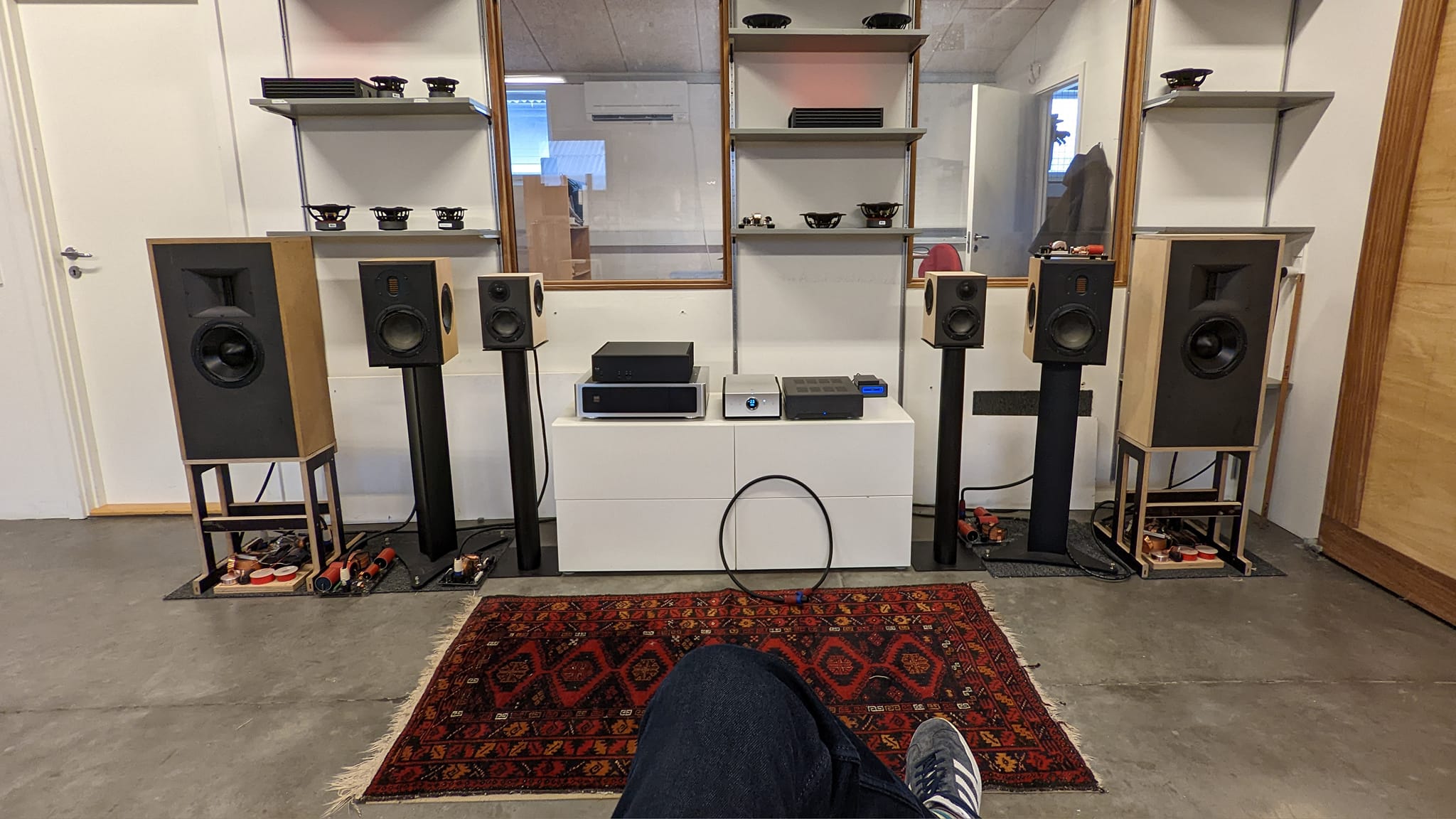
User tktran303's Collection of DIY designs here looking great

Some mindfood for the 8" - a concept by Purifi.
Paul Carmody's Virage - a full design, light on measurements but a fairly reputable designer.
.....and many more concepts within this thread, start reading. Most not fully documented or taken to finished stage though I suspect a few people are still perfecting their builds before showing them off. Remember you can drop people a friendly private message asking about how their progress is going.
DIY-Kits/Semi Commercial:
Yevgeniy’s PuriWave - 2-way stand mount with dual purifi passive radiators

Troels Gravesen Purifi 6661 - Semi-passive/Active plate amplified floor-stander

Troels Gravesen Purifi 6R - Passive bookshelf

Troels Gravesen Purifi Be - Looks like a revision to the above due to ribbon tweeter supply issues.
hificompass Puri Bliss BeWg - Passive bookshelf - I believe the plans are/were for sale.

Joseph Crowe's 1198 - I believe you have to get in touch via the webpage - floor-stand transmission line

Full Commercial:
March Audio Sointuva - arguably where "the bar has been set" for the Purifi 6.5 in a bookshelf chassis.

Jones Scanlon Baby Reds - self powered studio mixing monitors.

The Late Rick Craig's Selah Audio Purezza - A nice stand mount ribbon tweeter design, was available commercially but afaik discontinued, check SH market

Jachim Gerhard Surveyor's - stand-mounts , I believe there is/was a floor-stander made too

Dennis Murphy & Jim Salk's BePure2 - Floor stander - The legends behind the philharmonic BMR and BMR tower

and um, what ever this might be! https://www.audiocircle.com/index.php?topic=175599.0 - probably just a concept, I didn't read the thread. Likely Unobtanium tweeters and probably bottomless pockets required, if it is sold commercially.
Correction - the above was a concept which later evolved to the BePure2 - see this thread at AVSForums Post #10,174
https://www.avsforum.com/threads/th...rs-and-discussion-thread.939744/post-61186397
Further Build links:
Thrax Siren - a 2-way standmount
Jern 35 - 2 way standmount
Buchardt A500 Signature - Active 2 way standmount
WVL Serendipity - 2 way standmount
Taipuu Kero L active with FourAudio PPA-1000 dsp amps. - Not sure if available yet
Salk Sound BePure3 ... Holy **** I need to hear these.
Links to independent driver reviews:
https://www.erinsaudiocorner.com/driveunits/purifi_4/
https://www.erinsaudiocorner.com/driveunits/purifi_ptt65w04/
https://www.erinsaudiocorner.com/driveunits/purifi_ptt80x04-nab-02/ - the eight inch aluminum mid-woofer
https://www.erinsaudiocorner.com/driveunits/purifi_ptt6.5x04-naa-08/ - the 6.5 inch aluminum mid-woofer
https://www.erinsaudiocorner.com/driveunits/purifi_ptt6.5m-08-nfa-01a/ - the 6.5 inch dedicated midrange
Also - please consider visiting Erins Youtube Channel and subscribing! - a much needed light in the dark world of audio subjectivism.
https://audioxpress.com/article/tes...udio-6-5-midbass-transducer-from-purifi-audio
https://hificompass.com/en/reviews/purifi-audio-ptt65w04-01a-midwoofer
https://hificompass.com/en/reviews/purifi-audio-ptt40w04-01a-midwoofer
https://hificompass.com/en/reviews/purifi-ptt65w08-01b-ptt65x08-nfa-01
https://hificompass.com/en/reviews/purifi-ptt65m08-nfa-01a-65-true-midrange
http://www.troelsgravesen.dk/Purifi.htm
Original Post 02/04/2020:
With the group buys well underway the idea was bought up that a design thread be started to discuss build options.
Mine have arrived but I have no build materials and will not be able to get any until we come out of quarantine in (hopefully) three weeks time. I planned to start with a hybrid of purifi's SPK4/5 builds using the same AMT tweeter but maybe using a slot port with the 2.5khz crossover. That and I haven't done any AMT builds so it seemed like a good place to start.
I read of a guy in Aus planning on doing a line of passive and active speakers with the woofer so be interesting if he could chime in here.
So with no materials for the next at least 3 weeks, what better time to discuss build options! Fire away


A place to brainstorm and speculate on drivers and potential speaker builds for arguably, objectively, the best no-nonsense engineering-first traditional speaker drivers' money can buy - If you have a complete project underway, please start your own thread and post a link to it in here. Otherwise posting occasional random progress pics and info here is fine but we will keep full build discussion elsewhere.
We are also pleased to have @lrisbo of purifi occasionally check in and post here of which is much appreciated.
A tweeter is on the way 🤓
Updated 26/01/23: Added more build links and intro - (I may stop updating commercial builds moving forward as they are now coming in thick and fast)
Updated 16/06/22: Added builds and review links, updates to builds
Update 17/03/22: below
Time for a bit of consolidation due to this thread getting some hits, and purifi has now released quite a few scrunchy woofers
Links to known projects & commercial speakers using the Purifi drivers (please PM me if I need to add any)
Of course - www.purifi-audio.com , and the team behind the drivers here
Full DIY:
DIYA user @spresto9 has come up with these beauties with the 8" purifi woofer like to details and more pics HERE
Check out this 4" pocket rocket proof of concept build from the Purifi team - all the info you need to DIY!
Spk8 appnote download (.pdf)
@lrisbo Proof of concept Purifi SPK4 (superseded) - Passive stand-mount
@lrisbo Proof of concept Purifi SPK5 - Passive stand-mount - I believe these were at some point being made and sold commercially but have since been discontinued - there may be some floating around second hand market see here Celuaris SPK5 review ASR
@xrk971 PTT6.5/RS28F Waveguide Harsch XO - Passive stand-mount later evolved into a nice Stand mount and Floor standing Transmission Line
@Joe Rasmussen Somewhat Legendary 'Elsinore' - Has been given an (expensive) purifi remodeling. Wow. Skip ahead to post #4,746 for the juicy bits.
Rick Sykora and team's Directiva - Active stand-mount with excellent (objective) reviews, requires external amplification for each driver and an external DSP crossover.
@xrk971 's Raal 70-20xr and PTT6.5 - this one the tweeter is not readily available to DIYers but there may be ways to get it if you're crafty.
(sorry X, couldnt find a finished pic, and I'm out of attachments for this post)
User tktran303's Collection of DIY designs here looking great
Some mindfood for the 8" - a concept by Purifi.
Paul Carmody's Virage - a full design, light on measurements but a fairly reputable designer.
.....and many more concepts within this thread, start reading. Most not fully documented or taken to finished stage though I suspect a few people are still perfecting their builds before showing them off. Remember you can drop people a friendly private message asking about how their progress is going.
DIY-Kits/Semi Commercial:
Yevgeniy’s PuriWave - 2-way stand mount with dual purifi passive radiators
Troels Gravesen Purifi 6661 - Semi-passive/Active plate amplified floor-stander
Troels Gravesen Purifi 6R - Passive bookshelf
Troels Gravesen Purifi Be - Looks like a revision to the above due to ribbon tweeter supply issues.
hificompass Puri Bliss BeWg - Passive bookshelf - I believe the plans are/were for sale.
Joseph Crowe's 1198 - I believe you have to get in touch via the webpage - floor-stand transmission line
Full Commercial:
March Audio Sointuva - arguably where "the bar has been set" for the Purifi 6.5 in a bookshelf chassis.
Jones Scanlon Baby Reds - self powered studio mixing monitors.
The Late Rick Craig's Selah Audio Purezza - A nice stand mount ribbon tweeter design, was available commercially but afaik discontinued, check SH market
Jachim Gerhard Surveyor's - stand-mounts , I believe there is/was a floor-stander made too
Dennis Murphy & Jim Salk's BePure2 - Floor stander - The legends behind the philharmonic BMR and BMR tower
Correction - the above was a concept which later evolved to the BePure2 - see this thread at AVSForums Post #10,174
https://www.avsforum.com/threads/th...rs-and-discussion-thread.939744/post-61186397
Further Build links:
Thrax Siren - a 2-way standmount
Jern 35 - 2 way standmount
Buchardt A500 Signature - Active 2 way standmount
WVL Serendipity - 2 way standmount
Taipuu Kero L active with FourAudio PPA-1000 dsp amps. - Not sure if available yet
Salk Sound BePure3 ... Holy **** I need to hear these.
Links to independent driver reviews:
https://www.erinsaudiocorner.com/driveunits/purifi_4/
https://www.erinsaudiocorner.com/driveunits/purifi_ptt65w04/
https://www.erinsaudiocorner.com/driveunits/purifi_ptt80x04-nab-02/ - the eight inch aluminum mid-woofer
https://www.erinsaudiocorner.com/driveunits/purifi_ptt6.5x04-naa-08/ - the 6.5 inch aluminum mid-woofer
https://www.erinsaudiocorner.com/driveunits/purifi_ptt6.5m-08-nfa-01a/ - the 6.5 inch dedicated midrange
Also - please consider visiting Erins Youtube Channel and subscribing! - a much needed light in the dark world of audio subjectivism.
https://audioxpress.com/article/tes...udio-6-5-midbass-transducer-from-purifi-audio
https://hificompass.com/en/reviews/purifi-audio-ptt65w04-01a-midwoofer
https://hificompass.com/en/reviews/purifi-audio-ptt40w04-01a-midwoofer
https://hificompass.com/en/reviews/purifi-ptt65w08-01b-ptt65x08-nfa-01
https://hificompass.com/en/reviews/purifi-ptt65m08-nfa-01a-65-true-midrange
http://www.troelsgravesen.dk/Purifi.htm
Original Post 02/04/2020:
With the group buys well underway the idea was bought up that a design thread be started to discuss build options.
Mine have arrived but I have no build materials and will not be able to get any until we come out of quarantine in (hopefully) three weeks time. I planned to start with a hybrid of purifi's SPK4/5 builds using the same AMT tweeter but maybe using a slot port with the 2.5khz crossover. That and I haven't done any AMT builds so it seemed like a good place to start.
I read of a guy in Aus planning on doing a line of passive and active speakers with the woofer so be interesting if he could chime in here.
So with no materials for the next at least 3 weeks, what better time to discuss build options! Fire away


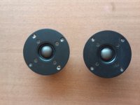

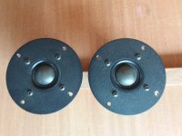


 ). The tweeter comes last.