I did some measurements of this circuit with some changes. The VAS stage is loaded by 1k to just show how it works together with the current mirror and the input stage.


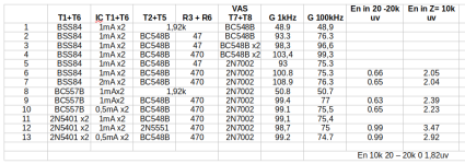
The table over the measurements.
Measurement 1: No current mirror just 1,92k instead to get the same current in T1 and T5.
2: Now we have a current mirror and it raises the gain of the circuit 44,4dB.
3: The VAS has now 2x BC548B. 1 mA In the driver and 6 mA in the VAS output as usual. 5 dB more gain
4: With the resistors in the current mirror increased to 470 ohm the current mirror shows its potential.
5: 2N7002 as VAS and back to 47 ohm mirror resistors.
6: We are back at 470 ohm. No difference at 100kHz but at 1.
7; Increased current in the input transistors. Max gain of the test at 1kHz.
8: BC 558B as input transistors and no current mirror. We lost 58dB gain.
9: Current mirror shines.
10: Now lower current in the input transistor but no great change.
11: 2N5401 is a popular input transistor especially at high voltages. No gain change.
12: 2N5551 as current mirror is a tick give as a tick less gain.
13: 0,5 mA for the input transistors doesn´t change much.
Input noise: BC557B and the BSS84 has both good noice figures but with the 2N5401 care in the planning is needed especially if you use the amp with a volume control at the input.
The BSS84 and the BC 557B has different strong sides so the actual amplifier topology decides wich one will fit the best.
The MOSfet might give lower RFI with higher current and the gate not rectifying. Maybe a tick lower distortion. Maybe higher ripple rejection.
The BC gives lower offset voltage and price + you find it everywhere.
Attachments
Last edited:
I presumed that the noise was only dependant of the input transistors so i only measured it with the different currents in each model of the input transistors.
I guess the Ein in measurement 1 to 6 will be the near equal. 7 and 8 too just as well 11 and 12.
I guess the Ein in measurement 1 to 6 will be the near equal. 7 and 8 too just as well 11 and 12.
I have designed couple of amps with MOSFET front end.
1. I would bias the input pair at 2mA each. With MOSFET, there is no current flowing through the gate. The is less concern with higher bias. It helps improve the gm of MOSFET a lot.
2. The current mirror, you need to find some transistors with no quasi saturation. Basically, some transistors exhibit low Collector impedance around low voltage region. That will affect your gain. BC548 is not a good chioce. BC337 would be better for the current mirror.
wrongI guess the Ein in measurement 1 to 6 will be the near equal
I checked some measurements again. Astonishingly i did not get the exakt the same results as this afternoon.
But I checked Ein in post 2 to 6 to be the same.
I also checked post 7 with BC 337-25. Surprise! The noise went up from 0,62uv to 0,76uv with 0 ohm input resistance.
The 1kHz gain was 0,7dB lower at 1 kHz and 0,6 lower at 100 kHz. 1 mA in the input transistors.
With the 2N7002 and the 470 ohms we still have about 1,45v Vce for the current mirror.
I also checked with R4 + R7 = 1kohm. Vce 0.92v. Gain 1kHz +1.1 dB, 100kHz -0.2dB.
! kohm Vce 0,5v. 1kHZ +0.4dB, 100kHz -0.7dB.
Looks like 1 v is near the lower limit for BC 548B at 1mA.
I would say that BC 547B is a better transistor at 1mA. I have checked It for use in the VAS stage and the output admittance raises fast when Ic goes over 2 mA.
I rechecked post1 in the table. It had pretty low OLG which made that the closed loop gain also was a little small.
With corrected gain i now get noise at 0 ohm in 0,67uv and with 10 kohm in 2.0 uv and that is more in line with our expectations.
The resistor should be 680 ohm with a single bipolar VAS.
With corrected gain i now get noise at 0 ohm in 0,67uv and with 10 kohm in 2.0 uv and that is more in line with our expectations.
The resistor should be 680 ohm with a single bipolar VAS.
Here is the topic regarding Quasi Saturation.
Usually, I use 100 Ohm Re for 1mA current mirror. 47 Ohm Re for 2mA current mirror. Just to keep the voltage drop on the resistor minimum, 0.1v in my case.
For a power amplifier, I don't care about thermal noise. I never have thermal noise issue before. Hum and buzz rejection is more critical.
I've got an application in mind for an NPN bipolar, running about 10mA, at low VCE. Imagine a cascoded current source or a full 4T Wilson mirror, that sort of thing. I'd prefer to avoid transistors that exhibit Quasi Saturation at 10mA, because their effective ro (=Vearly/Ice) is poor.
So I decided to measure a few transistors. Here are the results. The ones that my eyeball says "Yes, that looks like Quasi Saturation to me!!" are marked with red arrowheads.
Surprisingly, a few Author Favorite transistors seem to Quasi Saturate at 10mA:
So I decided to measure a few transistors. Here are the results. The ones that my eyeball says "Yes, that looks like Quasi Saturation to me!!" are marked with red arrowheads.
Surprisingly, a few Author Favorite transistors seem to Quasi Saturate at 10mA:
- Bob Cordell's preferred 2N5551: yes it...
- Mark Johnson
- Replies: 209
- Forum: Solid State

Usually, I use 100 Ohm Re for 1mA current mirror. 47 Ohm Re for 2mA current mirror. Just to keep the voltage drop on the resistor minimum, 0.1v in my case.
For a power amplifier, I don't care about thermal noise. I never have thermal noise issue before. Hum and buzz rejection is more critical.
I looked at the curve of BC 547 in post 15 in that thread. It seems to fit my opinion. Avoid to use Bc5xx at currents more than 2 mA.
I have seen most Quasi saturation in video output transistors and its is much worse at high frequency.
At the BC5xx the early voltage that sinks with higher current is a greater problem for me than quasi saturation.
If you choose larger transistors to avoid these you will get larger capacitances and problems with that.
The purpose of the thread was only to highlight the current mirror and the input transistors and how they connect to VAS.
Choice of transistors and different VAS topologies was supposed to be subject for a later thread.
2 to 6 are almost the same, but 1 (and 8) - without current mirror @ 1st stage load - are better at least 3 dB [ see here https://www.patreon.com/posts/nezhelatelnost-86795812 - "Undesirability of active loading of the input low-noise stage"]Ein in post 2 to 6 to be the same
the gain (with current mirror) is better but the noise is worseSee post 7.
I did a new check now with components as i would choose from the table.
1 mA input BSS84 transistor current. 1.92 kohm to - or current mirror with BC548B and 470 ohm.
With the resistors the noise was 0.63 uv and 2.0 uv with 10 kohm in.
With the current mirror the noise was 0.62 and 2.0 uv.
With my circuit and with my measurements the noise is practically the same so i say again: In this circuit the noise is determined by the input transistors.
I used TI:s TINA as simulator.
Are the T2 and T6 in your circuit attributed as "noiseless"? Please attach your TINA circuit file.In this circuit the noise is determined by the input transistors.
No they are just standard BC548B from the simulators transistor list.

Replace T5 + R4 with a single 1,92k when you need to.
Replace T5 + R4 with a single 1,92k when you need to.
BTW, I don’t think simulation facts in Quasi Saturation.
Don’t overstate the noise performance. You won’t hear it for line level input of a power amp. Something in the chain at the front would dominate the noise.
Don’t overstate the noise performance. You won’t hear it for line level input of a power amp. Something in the chain at the front would dominate the noise.
The simulation seemed to take oversaturation when i tested 2N 5401 and 5551 as VAS in a low voltage amplifier.
I made fourier tests of how high full power frequency i could get.
If i remember correct FZT757 was better. I didn´t take notes. Just remember to test power bandwith and distortion at 20 kHz too.
I am looking for -120 dB distortion and noise or better. Just to have a good safety margin under the hearable. To me noise, ripple rejection and distortion are of equal interest. And i hate to hear a digital freak claim that digital is better.
I asked not for a picture, but to attach a schematic file for simulation in TINAReplace T5 + R4 with a single 1,92k when
I dont have. My computer closes TINA down when it is going to rest. And that happened yesterday. I will draw a new one.
May be you will better use MICROCAP XII [free here https://www.patreon.com/posts/podstrakhoval-12-84096514 ] instead of TINAI dont have. My computer closes TINA down when it is going to rest.
- Home
- Amplifiers
- Solid State
- Input stage + current mirror and VAS analysis.