Multibit DACs with current output have had a cult following for a long time but recently they have become very popular at diyaudio e.g. due to Miro's diy dac boards. Diyers have tried a variety of I/V stages and there are quite many subjective evaluations of these. However not that many measurements. So I decided to provide measurements of some of the popular alternatives.
DAC
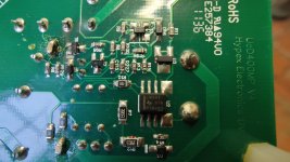
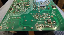
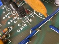
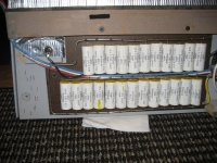
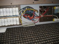
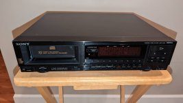
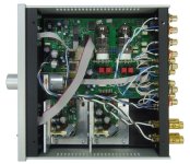
The DAC used in this test is my PCM1702 board that uses PMD100 as digital filter. The board has PCM1702 L-grade chips that were used in Denon CD players. L-grade is not specified in the datasheet but all my L-grades measure about the same as K-grade. I have also J-grade chips but they measure much worse than the L-grades.
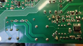
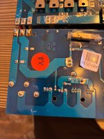
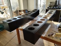
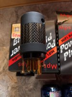
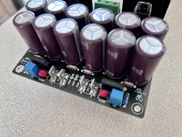
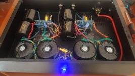
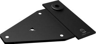
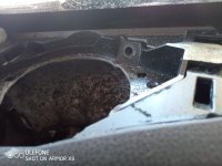
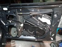
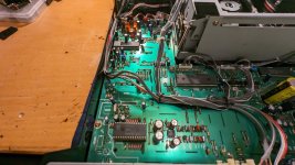
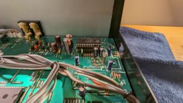
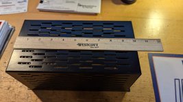
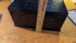
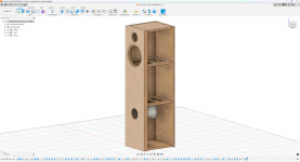
Here is the DAC board with separate I/V stage.
The DAC board caters directly for OPA1611, AD844 and AD811 (by populating appropriate I/V resistors and capacitors). Other I/V alternatives can be built as small "hat" boards that fit directly to the op amp sockets on the DAC board.
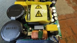
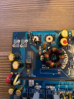
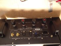
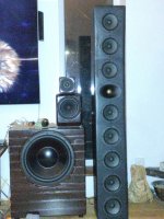
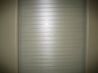
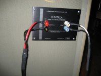
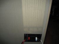
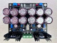
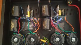
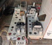
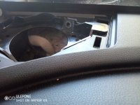
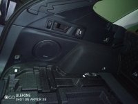
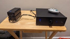
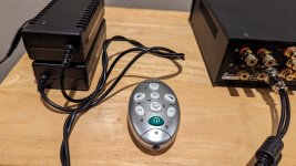
Here is a picture of the test setup.
The PSUs for the DAC board and the ADC board (ES9822PRO) are my "silent switchers" powered by power banks. DAC PSU board has 2 TPS7A39 dual regulators for +/-12V and +/-5V and a "raw" 5.5V output for the digital filter regulators on the DAC board. The connection to PC from DAC/ADC is provided by my STM32F7 USB-to-I2S board.
Lineup
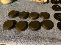
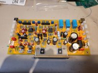
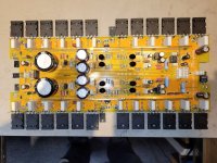
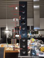
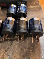
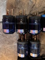
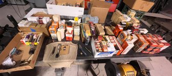
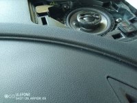
Here is the I/V lineup for this test.
From left to right: OPA1611, AD844, AD811, OPA861, Folded cascode CEN clone, BJT
OPA1611
OPA1611 is often recommended for I/V duties. Here it will be used as typical op amp I/V stage in DAC datasheets so it will act as a baseline for other measurements.
BOM cost (single): 5 EUR.
AD844
AD844 is used without feedback (as in AYA dacs by Pedja Rogic). Input impedance is relatively high (50 ohms) so some stack 3 or more AD844s. Here only one is used.
BOM cost: 15 EUR.
AD811
AD811 I/V stage is based on Walt Jung's
article in Audio Amateur 2/92. I used 1k stabilizing resistor. Input impedance is about 1 ohm.
BOM cost: 15 EUR.
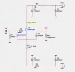
OPA861
OPA861 is used as in the
I/V stage of AYA II by Pedja Rogic.
BOM cost: 10 EUR.
Folded cascode CEN clone
This is based on the
folder cascode CEN by EUVL.
This is not the original folded cascode CEN but a clone.
I used 2SK209GRs as buffers. Input impedance is about 13 ohms up to 100kHz.
BOM cost: 30 EUR. This is the only one of the tested I/V stages that uses obsolete parts (2SK170/2SJ74). BOM Cost assumes matched jfets from diyaudiostore.
BJT
This is a slightly modified version of
ES9018 I/V by Sérgio Santos (
@smms73).
I added a similar 2SK209GR buffer as in CEN and modified some resistances for lower current consumption.
On paper (i.e. simulator) this I/V stage has very low impedance (200mOhms up to 100kHz). Parts count is high but it uses ubiquitous BJTs.
BOM cost: 10 EUR.
I/V resistor and cap is 1.5kOhms || 2.2nF on all tested I/V stages.
Measurements
I made the following measurements on each I/V stage:
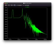
- THD(+N) at 0dBFS
- Noise (DAC playing -180dBFS)
- THD vs. level sweep at 997Hz.
Measurements are shown in subsequent posts.


