Hey all,
I just cobbled together a sim for a UcD headphone amp. This is my first amp design from scratch.
This is a first step towards a 100W amp. I figured by ruling out most of the power stage, it'll be easier to get something working. My emphasis is simple and easy to build.
Briefly, it's built around the LT6274. One unit for the comparator and 3 as unity gain buffers acting as the power stage. Comparator output is clamped by zeners to limit output swing and not over drive the power stage.. The hysteresis is added in hopes of avoiding driving the comparator into deep saturation. There's no feadback compensation network, just a divider to set gain, and the output filter is heavily bypassed. In a rev. 2, I might revisit a proper comparator and the simplest way to manage differing supply and output voltages between that and the power stage.
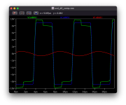
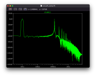
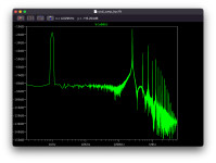
I set out measuring propagation delay (285ns) doing all the math for lead/lag networks but in the end I couldn't get it to oscillate much above 150kHz, which is what lead me to rip out all the compensation and bypass the output filter. It switches around 250kHz but still has rise/fall times 200ns-300ns. It provides 5dB gain, clipping just past +/-0.8V input / +/-2V output, delivering ~50mW RMS into 18 ohms.
All in, 4 op amps, 12 passives on split 9V supplies (easy with batteries).
I'm excited to have gotten it working, but not happy about not understanding the lead/lag compensation.
All input welcome.

I just cobbled together a sim for a UcD headphone amp. This is my first amp design from scratch.
This is a first step towards a 100W amp. I figured by ruling out most of the power stage, it'll be easier to get something working. My emphasis is simple and easy to build.
Briefly, it's built around the LT6274. One unit for the comparator and 3 as unity gain buffers acting as the power stage. Comparator output is clamped by zeners to limit output swing and not over drive the power stage.. The hysteresis is added in hopes of avoiding driving the comparator into deep saturation. There's no feadback compensation network, just a divider to set gain, and the output filter is heavily bypassed. In a rev. 2, I might revisit a proper comparator and the simplest way to manage differing supply and output voltages between that and the power stage.
I set out measuring propagation delay (285ns) doing all the math for lead/lag networks but in the end I couldn't get it to oscillate much above 150kHz, which is what lead me to rip out all the compensation and bypass the output filter. It switches around 250kHz but still has rise/fall times 200ns-300ns. It provides 5dB gain, clipping just past +/-0.8V input / +/-2V output, delivering ~50mW RMS into 18 ohms.
All in, 4 op amps, 12 passives on split 9V supplies (easy with batteries).
I'm excited to have gotten it working, but not happy about not understanding the lead/lag compensation.
All input welcome.
Attachments

A hysteresis band has the tendency to reduce switching frequency.
A very convenient and inexpensive chip combination for headphone class-d is LM360(1) / 74HC(U)04. This is a true rail-to-rail application and many opamps do not drive more than 10mA that way !!
With faster chips (<50ns) and such small power, you could drive the switching frequency into the MHz range, also obtaining a smaller LC filter that'd be easier to put closer to the chip.
Last edited:
Interesting combo. Looks like I could just run the comp on a 9V battery, but need a supply of some sort for the logic buffer. Would you happen to know of a pair that are supply compatible?
Thanks for the suggestion!
Thanks for the suggestion!
Ended up going in a different direction.
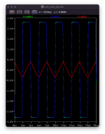
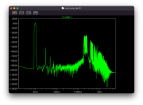
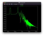
Propagation delay is ~200ns, rise/fall ~500ns, switching at 160kHz - not great, but it works. Compared to previous, noise floor is higher, but no harmonics and plenty of power. 6dB gain, 1.4W RMS into 18 ohms.
Still haven't figured out the lead network but I'm tickled to have gotten this far with just 6 transistors.