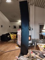
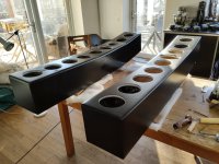
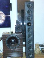
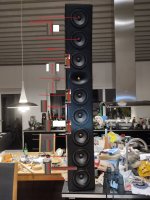
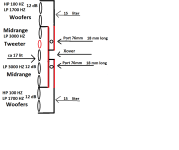
I have build a 2,5 way linesource with 8 Peerlees fls-0512 5,9 inch midwoofers per side, and using a Audax "gold" TW025A28 in a WG as tweeter.
Diffucult to measure with a speaker thats 152 cm in hight, and have drivers from bottom to the top.
The linesource will also be mounted on the wall, with tweeter at 3/4 up on the tv.
Measurements done with speaker 1 m obove the floor, faceing into biggest reflexfree area in my house.
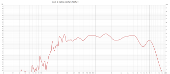
measurements on 2 lower woofers together from 1 m (connected 8+8 ohm)
Done measurements on 2 higher woofers together from 1 m(connected 8+8 ohm)
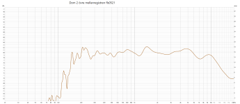
Done measurements on 2 lower midranges together from 1 m(connected 8+8 ohm)
and done measurements on 2 midranges over and under the tweeter "MTM" together from 1 m(connected 8+8 ohm)
and tweeter measurements from 1 m
The drivers are then paralellconnected in pairs to 16 ohm, and then in serie outside at the xover so 8 ohms load.
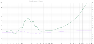
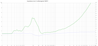
Problem is that measuremenrs still become 16 ohms, and when i put it in VitauXcad nothing becomes "right"
So making simulations doesen´t help mutch, and don´t look as my test measurment on hole speaker.
And room is 3,8 meter frontwall to backwall, speaker steals 24 cm and in total with my head and sofa tha maximal listeningsdistance is 3,2 meter.
Speaker play real good today crossed at 1,5K and ca 3K (with lots of xover work), but would like to be able to do correct simulations in VitauXcad.
One more problem is my health, so can´t carry around the ca 35 kg high "thing"
Any suggestions on anything of my problems?
Diffucult to measure with a speaker thats 152 cm in hight, and have drivers from bottom to the top.
The linesource will also be mounted on the wall, with tweeter at 3/4 up on the tv.
Measurements done with speaker 1 m obove the floor, faceing into biggest reflexfree area in my house.
measurements on 2 lower woofers together from 1 m (connected 8+8 ohm)
Done measurements on 2 higher woofers together from 1 m(connected 8+8 ohm)
Done measurements on 2 lower midranges together from 1 m(connected 8+8 ohm)
and done measurements on 2 midranges over and under the tweeter "MTM" together from 1 m(connected 8+8 ohm)
and tweeter measurements from 1 m
The drivers are then paralellconnected in pairs to 16 ohm, and then in serie outside at the xover so 8 ohms load.
Problem is that measuremenrs still become 16 ohms, and when i put it in VitauXcad nothing becomes "right"
So making simulations doesen´t help mutch, and don´t look as my test measurment on hole speaker.
And room is 3,8 meter frontwall to backwall, speaker steals 24 cm and in total with my head and sofa tha maximal listeningsdistance is 3,2 meter.
Speaker play real good today crossed at 1,5K and ca 3K (with lots of xover work), but would like to be able to do correct simulations in VitauXcad.
One more problem is my health, so can´t carry around the ca 35 kg high "thing"
Any suggestions on anything of my problems?
Attachments
So, are you concerned with getting the sim right, or are you concerned with getting the x-over right?
They go hand in hand i belive in a way.So, are you concerned with getting the sim right, or are you concerned with getting the x-over right?
Sound is good but dont know impedance curve, and also like to learn by "testing"
Im learing diy and want to be able to simulate even a Linesource, and compare simulations with real measurements.
I don't use VitauXcad, so can't help you with that.
Can you show the driver responses in your sim? I'm confused as to where things are being filtered.
Are you intentionally running the bottom woofers beyond about 300hz?
Can you show the driver responses in your sim? I'm confused as to where things are being filtered.
Are you intentionally running the bottom woofers beyond about 300hz?
Last edited:
Just using LP 12 dB for 2 lowest and 2 highest woofersCan you show the driver responses in your sim? I'm confused as to where things are being filtered.
Are you intentionally running the bottom woofers beyond about 300hz?
Attachments


2 woofers at bottom and top are LP at ca 1500 hz, and rolls of by them selfes.The next four woofers are going to run up to meet the tweeter at about 1.5k right?
The 4 other in the middle have a HP at ca 150 hz (10mH coil+ 150uF), and a LP at ca 3100 hz
All is 12 dB filtering
Attachments

Do you mean all 4 woofers? (2 top & 2 bottom)Change just the outer woofer filters to roll -off around 250,
So add a HP of 250 hz?
Likely be helpful to at least do off axis measurements, or even just sim with factory frd off axis on baffle in the vertical.
Then you will get a good idea how fun getting vertical to work is.
Summing on axis wont tell you much.
If you measure on axis centered for each driver. you need to set XY right in sim.
Have to account for the center to center distance of the driver mounting, so you see the combing from phase.
Horizontal will be easy, would just lock in on the vertical.
Just to be completely clear before I start soldering things!Yes. Something around 250hz. Maybe the 6mH, and 50uf will be close.
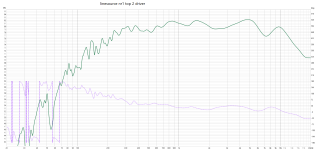
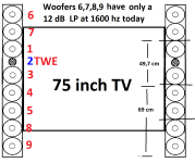
This 2 measurements are without a xover, from top 2 woofers and 2 bottom woofers. ( nr 6,7,8 and 9 at my skiss)
As you see in pics " linesource nr1 top 2 driver", woofer nr 6 & 7 at the topp falls of quite nice around 300 hz (by them selves)
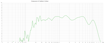
Also in pics "linesource nr1 bottom 2 driver" measurements without a xover for the 2 woofers nr 8 & 9, shows it falls of around 230-ish hz ( but not as pretty as the 2 top woofers)
But despite these measurements, do you think I should try adding a 12 dB HP filter around 250 Hz on woofer no. 6,7,8 & 9?
Attachments
As I mentioned., line arrays, and 2.5 ways, are not my area of expertise. I do enjoy Sims of passive x-overs, but there will be others who know more and can guide you better. Weekends are slow. You'll get more input soon I think.
I am curious about the sim results with the lower x-over on the outer woofers.
I am curious about the sim results with the lower x-over on the outer woofers.
Your outer woofers are going to almost to 2k currently. (As shown in post #9.)
Your mids and tweeter are going to 4k. (As shown in post #9.)
I guess what I'm suggesting, is to filter the outer woofers to be down 6dB at about 250hz, and seeing what the speaker response looks like in a sim.
Your mids and tweeter are going to 4k. (As shown in post #9.)
I guess what I'm suggesting, is to filter the outer woofers to be down 6dB at about 250hz, and seeing what the speaker response looks like in a sim.
Last edited:
I am not 100% sure but was the idea of a 250Hz "roll off" for the woofers based on the idea of removing the bass drivers mid frequencies and phase interactions from the overall response?
Hence the staring point given of 6mH and 50uF which should start the 4 woofer roll off/ decrease output at 250Hz? with their response by 1KHz well out of the picture -30 to 40dBs or so.
I haven't checked in a sim but 6mH plus lots of capacitance should start to curtail the mid output of an 8ohm drivers response. The idea sounds sensible enough to try and break this down into bite sized chunks.
Hope the sun is shining in Sweden today.
It depends on which drivers you want to have high frequencies in. I would assume that the outer woofers should not go high in frequency, but I've not looked at arrays much. I suspect there's more than one way to design it.
I see that there are no entries for X,Y,and Z. Perhaps this is intentional since it's a curved array.
I see that there are no entries for X,Y,and Z. Perhaps this is intentional since it's a curved array.
- Home
- Loudspeakers
- Multi-Way
- Linesource measurements and xoverbuilding