When you measure. We all do it differently. Here's an idea. You can place the tall speaker on stands horizontally in order to get the woofers away from the floor. Likely a 2 man job, and awkward.
I use gated measurements. It's true that accuracy below 300hz can be limited, but there's workarounds that can help.
For graphs, I like 5dB scales. Just easier to read, and more commonly used.
I use gated measurements. It's true that accuracy below 300hz can be limited, but there's workarounds that can help.
For graphs, I like 5dB scales. Just easier to read, and more commonly used.
Last edited:

I am not 100% sure but was the idea of a 250Hz "roll off" for the woofers based on the idea of removing the bass drivers mid frequencies and phase interactions from the overall response?
Yes, that and also the outer woofers supply baffle step correction. In addition, it may open some options on the mid to tweeter x-over point, since the speaker SPL will be lower above 1k.. I don't know how low that tweeter can cross, but depending on SPL requirements, I might go lower.
Yes, that and also the outer woofers supply baffle step correction. In addition, it may open some options on the mid to tweeter x-over point, since the speaker SPL will be lower above 1k.. I don't know how low that tweeter can cross, but depending on SPL requirements, I might go lower.
Will try to do that when i get some liftinghelp 👍When you measure. We all do it differently. Here's an idea. You can place the tall speaker on stands horizontally in order to get the woofers away from the floor. Likely a 2 man job, and awkward.
I use gated measurements. It's true that accuracy below 300hz can be limited, but there's workarounds that can help.
For graphs, I like 5dB scales. Just easier to read, and more commonly used.
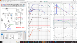
And now iv´e tried to "trick" SLP-Trace in VituaXcad, by halved the ohm scale and then create a zma file for every indevidual woofer.
So now ZMA/impedance files are "more" correct, and i maby have more to work with in my simulations...
Possibly need a notch around 1200 hz, but we will see.
best regards John
Attachments
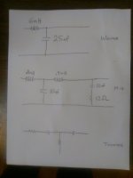
The mid filter.
That 6.8mH coil, and 2.2 ohm resistor is dropping your impedance. What is the purpose of that leg? If you need to shape the response, there may be better options.
That 6.8mH coil, and 2.2 ohm resistor is dropping your impedance. What is the purpose of that leg? If you need to shape the response, there may be better options.
The two bottom woofers in series would be 16 Ohms. When the two top woofers are added, (also 16 ohms), the woofer filter sees 8 ohms. That would be like a sim for one woofer, but with a 6dB higher spl. I'm not defending software, but maybe you are misinterpreting it.
How low can that tweeter cross?
Could you post the mid, and tweeter frd, and zma files. I use PCD software. PCD I could play with it on my computer for a comparison.
I would again suggest gated measurements.
How low can that tweeter cross?
Could you post the mid, and tweeter frd, and zma files. I use PCD software. PCD I could play with it on my computer for a comparison.
I would again suggest gated measurements.
Last edited:
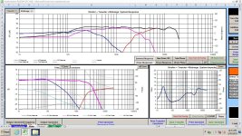
This is how I would try to make things work.
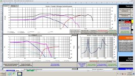
The low end looks like it's rolling off, but that is due to the gated measurements. There's no high-pass on the mid.
Don't look at the low end. It looks like these files had tails added,which is something I only tried recently. Mostly look at the filter transfer functions. Outer woofers would roll off early, like the blue response, and most of the mid-range (red response) , is from the mids.
Attachments
Last edited:
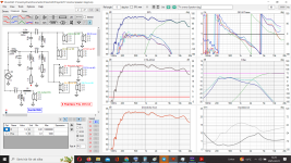
Jawen would you mind showing us what 6mH and 50 uF does do when applied to the top filter leg, simply replace your existing values and post the results if you don't mind.
Maybe play around a little bit on tweaking the values just to get a nice cut off of the 4 woofers response at 250Hz or so. Maybe it will show a huge suck out, or certainly mess up the flatness of the response. It should be something close to temp25's data in terms of roll off.
Maybe play around a little bit on tweaking the values just to get a nice cut off of the 4 woofers response at 250Hz or so. Maybe it will show a huge suck out, or certainly mess up the flatness of the response. It should be something close to temp25's data in terms of roll off.
I own a nice set of line arrays and have measured them a lot. I discovered early on the the 'traditional' methods of speaker measurement didn't really apply to line arrays. I ended up getting my best results from a series or mixture of listening position measurements. This of course takes into consideration of the affect the room has on your speakers.
Regards,
Dan
Regards,
Dan
Its 12 dB HP att ca 200 hzThe mid filter.
That 6.8mH coil, and 2.2 ohm resistor is dropping your impedance. What is the purpose of that leg? If you need to shape the response, there may be better options.
And yes it lower the impedance.
Do you mean its better to just have the 100-150 uF coil, and have 6 dB HP?
Correct!The two bottom woofers in series would be 16 Ohms. When the two top woofers are added, (also 16 ohms), the woofer filter sees 8 ohms. That would be like a sim for one woofer, but with a 6dB higher spl. I'm not defending software, but maybe you are misinterpreting it.
But its small differances in measurements on upper woofers and bottom woofers, and poeple all the time say´s "measure all driver" and then simulate.
Think 2500 hz is no problem!How low can that tweeter cross?
Yes i will post mids and twe frd and zma files later today 👍Could you post the mid, and tweeter frd, and zma files. I use PCD software. PCD I could play with it on my computer for a comparison.
I would again suggest gated measurements.
Best regards John
Here you go Ray 🙂Jawen would you mind showing us what 6mH and 50 uF does do when applied to the top filter leg
Attachments
REW crasch as usual the 10 feb when i did inhouse measurements with speaker 92 cm obove the floor, so i only have these saved as PNG files with 1 dB scale.Could you post the mid, and tweeter frd, and zma files. I use PCD software. PCD I could play with it on my computer for a comparison.
And from PGN use SPL Trace tool in VituaXcad2.
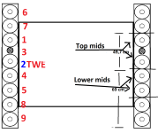
Just to be clear, topp 2 midranges is the ones obove and under the WG tweeter.
2 lower midranges, is the 2 between 2 lower woofers and the midrange under the WG tweeter.
regards John
Attachments
Just a reminder. I'm a newbie at 2.5 ways, and line arrays, so maybe don't assume I know what I'm doing here.
I can't sim the mid section of your filter in PCD. I really can't tell what it's doing.
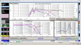
Here is a sim of a 2.5 way using my gated measurements of a 5.25" Peerless woofer. This may have a similar response to yours. I don't know that this filter is a good one, but it seems like maybe it is. Maybe you can try it in your sim, and see if anything is usable.
I can't sim the mid section of your filter in PCD. I really can't tell what it's doing.
Here is a sim of a 2.5 way using my gated measurements of a 5.25" Peerless woofer. This may have a similar response to yours. I don't know that this filter is a good one, but it seems like maybe it is. Maybe you can try it in your sim, and see if anything is usable.
Attachments
Are you sure about the impedance of the woofers? That's making the x-over very difficult, at least filtering down low creates problems.. My filter above will not work with it at all. Do you have the factory data by chance?
Does your amp handle very low speaker impedance?
Does your amp handle very low speaker impedance?
Last edited:
The Data in post 33 is interesting but it doesn't show what happens if we cut the bass drivers out of the overall picture below 250Hz, they are still playing up to 1KHz.
Forgetting questions or ideas for the moment, how do you feel about the current sound. As suggested maybe it is worth doing an average over the listening area which is the TV sofa. Maybe the area where you were thinking you needed a notch filter at 1.2KHz how does that look in separate measurement's across the width of the sofa. Is it hot directly on axis, but isn't there on the ends of the sofa ?
Forgetting questions or ideas for the moment, how do you feel about the current sound. As suggested maybe it is worth doing an average over the listening area which is the TV sofa. Maybe the area where you were thinking you needed a notch filter at 1.2KHz how does that look in separate measurement's across the width of the sofa. Is it hot directly on axis, but isn't there on the ends of the sofa ?
Here's a sim of just 3 drivers, and not in an array. There's some padding on the tweeter, so in the array, the tweeter needs no padding because the extra woofers boost their range more.
I can post the filter later. It's not terribly complicated.
Rolling the woofers off earlier did not seem to add as well to the other woofers below 100hz. So, here the .5 woofers go higher than what I was shooting for.
I can post the filter later. It's not terribly complicated.
Rolling the woofers off earlier did not seem to add as well to the other woofers below 100hz. So, here the .5 woofers go higher than what I was shooting for.
Attachments
Last edited:
Yes hereDo you have the factory data by chance?
Does your amp handle very low speaker impedance?
Now when testing yes, it´s a 2 ohm stable Krell
But will use a more ordenary receiver later, so dipp to 3 ohm is okey i think.
Attachments
Specs say 8 ohmAre you sure about the impedance of the woofers?
But all my measurements are 2 in series, so 16 ohm ( but i trick to make the ZMA files, halved the scale)
- Home
- Loudspeakers
- Multi-Way
- Linesource measurements and xoverbuilding