Recently I came across Mark Johnson's thread "VRDN: bipolar regulator PCB for line level ckts: ±11V to ±20V @ 1.5A with "De-Noiser" "
https://www.diyaudio.com/community/...l-ckts-11v-to-20v-1-5a-with-de-noiser.355883/
and instantly became a fan.
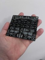
Here is a redraw of his schematic done just for fun. I named it "Butterfly DN". The PCB can be made by hand if you like, it has only two layers.
IT HAS NOT BEEN TESTED YET!
I have ordered some PCBs and will be testing soon.
I will be updating this thread with pictures.
For how to set it up, please visit the first post of the original thread:
https://www.diyaudio.com/community/...l-ckts-11v-to-20v-1-5a-with-de-noiser.355883/
BOM, Part numbering on the PCB and component sizes are exactly the same.
Heat Sink thermal resistance: 6.2C/W - 11.4C/W, depending on the length of the heatsink used (ref. attached pdf)
Board Size: 103,5mm x 91,5mm
Added:
Have fun!
Alexander
Disclaimer
This thread is made by a fan, it is not affiliated in any way to Mark Johnson's work and the original VRDN thread.
This layout is a DIY project done by me, provided "as is", with no official guarantee it will work.
https://www.diyaudio.com/community/...l-ckts-11v-to-20v-1-5a-with-de-noiser.355883/
and instantly became a fan.
Here is a redraw of his schematic done just for fun. I named it "Butterfly DN". The PCB can be made by hand if you like, it has only two layers.
I have ordered some PCBs and will be testing soon.
I will be updating this thread with pictures.
For how to set it up, please visit the first post of the original thread:
https://www.diyaudio.com/community/...l-ckts-11v-to-20v-1-5a-with-de-noiser.355883/
BOM, Part numbering on the PCB and component sizes are exactly the same.
Heat Sink thermal resistance: 6.2C/W - 11.4C/W, depending on the length of the heatsink used (ref. attached pdf)
Board Size: 103,5mm x 91,5mm
Added:
- Optional half rectification diodes D98 & D99 have their own place on the PCB. Remember, they are only used for half rectification, when using a transformer with only ONE secondary. They are marked with a *
- Added an optional resistor (R23, R24) in parallel to every one of the Variable resistors (VR1, VR2), in case you want to replace the Variable resistors by a fixed one.
- 2x Outputs, CON1 and CON2. CON1 supports many readily available connectors. CON2 supports Faston terminals OR Europlug
- Added R100, a way to connect the ground plane to chassis via the top right mounting hole. You can short it or use a resistor 3-10ohm
Have fun!
Alexander
Disclaimer
This thread is made by a fan, it is not affiliated in any way to Mark Johnson's work and the original VRDN thread.
This layout is a DIY project done by me, provided "as is", with no official guarantee it will work.
Attachments
-
sink_e-3082604-2.pdf690.6 KB · Views: 433
-
 IMG_0629.jpg467.7 KB · Views: 648
 -
 IMG_0628.jpg470.9 KB · Views: 673
 -
ButterDN1.5.2_Gerber.zip70.8 KB · Views: 297
-
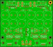 ButterDN152_TOP.JPG544.9 KB · Views: 646
 -
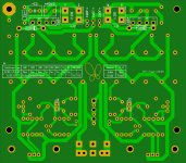 ButterDN152_BOTTOM.JPG355.9 KB · Views: 593
 -
TOP.pdf54 KB · Views: 303
-
Bottom (Mirrored).pdf14.2 KB · Views: 255
Last edited:

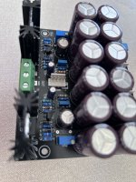
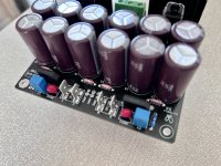
Finally the first PCBs have arrived!

Attachments
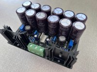
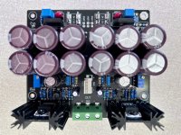

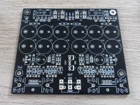
v1.5.1, Reversed the regulators by 180 degrees. you could not access the heatsink screw because of the location and hight of the capacitors.
This revision is considered final. I have deleted all previous files, feel free to download the current/ final gerber files.
This revision is considered final. I have deleted all previous files, feel free to download the current/ final gerber files.
I just wanted it to look stylish. And yes, the butterfly was the concept behind the design. Plus there is a little bit of OCD regarding symmetry
Alexander (and Mark),
I want to thank you both for the efforts you've put into these posts and the development. I'm looking forward to dropping this PSU into its own 1U case to power an 80s preamp mounted within its own 1U case. I'm considering pimping this denier design by adding (a largely unnecessary) OLED dual-channel oscilloscope screen showing the mains AC and output DC. Why the heck not? Just for fun...
Cheers,
Tim
Hi Turion64!
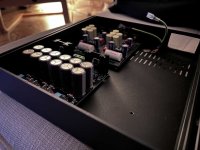
I made this version due to specific chassis constraints. I chose this box, added a toroidal transformer, an xlr type connector for the output and a standard IEC with fuse and switch module for input and it fits perfectly:
https://modushop.biz/site/index.php?route=product/product&path=33_286&product_id=517
Other than that there should be no difference regarding sound, the design is the same as the original.
Please share your results and thoughts regarding your project and feel free to ask if you need any info
Best regards, Alex
You must have been constrained in both the height of the 2200uF caps as well as the heatsinks since the chassis is only 40mm tall? I really wasn't expecting a differences with your boards but I will use your boards as a testing platform for Sparkos regulators to see if they bring any advantages in SQ. I've used them in other PS circuits for my other DIY preamps and they have made a positive difference (subjective? Well, maybe). I will obviously have to make some minor circuitry changes because the sparkos are not exact LM317&337 drop in replacements.
Cheers
Cheers
- Home
- Amplifiers
- Power Supplies
- Bipolar regulator PCB with "De-Noiser", a different PCB layout from the known schematic