Hi. I'm starting this new thread about my Accuphase P-7100 amplifier clone. Most of the owrk is already done, and I just completed both amplifier module last week.
I tested and preset both amp modules today and everything is looking good. I pre-set the bias at 5mV on the final instead of the specs 20mv (20mv / 2x 0.47R = 21ma / Transistors
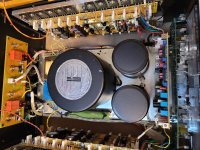
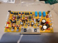
The front end and Meter/Softstart/Protection PCB are tested and working fine. The main +/-75V Power supply is already assembled on the chassis. It is made of a massive recycled Rotel potted power transformer, two large 51,000uF/100V Kemet power capacitor, as the original just one 35MB100A, 35A, 1kV rectifier bridge and a copper GND bus bar as the original.
I'm trying to emulate as far as possible the original, since I know the Accuphase sound and love it. I went throught the service manual and decoded the detailled BOM that list all the type of resistors and caps used where (film, carbon, MOX, carbon film, and as far as possible the same caps series and type).
The PCB, original clone of very good quality (2mm, gold plated) are from ebay. All the pcb were replica of the original and match the service manual schematic, except the Meter/Softstart/Protection PCB. The original processor amp control was replace with discrete circuit, and the usual uPC1237 protection IC, but there was no info on it, and no part values. I had to find the circuit and test my mods by myself. The input stage pcb is the same circuit but the parts ID are different from the original schematic, and some small differences are there as well. I documented the changes and wire the board accordingly. Chassis is a clone from Aliexpress.
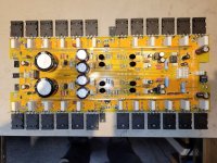
The original amp section used 2SC5358/2SA1986 (230/15A), me I'm using the 2SC5200/2SA1943 (same 230/15A) that I bought years ago, and match them myself.
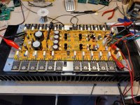
I used thermal spread aluminum bars to mount the power amp transistors, and to add rigidity to the clone heatsink made of two section. The output amp module is now solid as a brick. The amp pcb also inclded nice brass bus bar and input transistor pairs rubber caps, as the original.
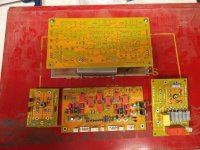
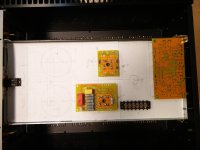
Here some pictures of the PCB. There are some extra PCB such as the rectifier PCB and Softstart and Ground Lift PCB.
I tested and preset both amp modules today and everything is looking good. I pre-set the bias at 5mV on the final instead of the specs 20mv (20mv / 2x 0.47R = 21ma / Transistors
The front end and Meter/Softstart/Protection PCB are tested and working fine. The main +/-75V Power supply is already assembled on the chassis. It is made of a massive recycled Rotel potted power transformer, two large 51,000uF/100V Kemet power capacitor, as the original just one 35MB100A, 35A, 1kV rectifier bridge and a copper GND bus bar as the original.
I'm trying to emulate as far as possible the original, since I know the Accuphase sound and love it. I went throught the service manual and decoded the detailled BOM that list all the type of resistors and caps used where (film, carbon, MOX, carbon film, and as far as possible the same caps series and type).
The PCB, original clone of very good quality (2mm, gold plated) are from ebay. All the pcb were replica of the original and match the service manual schematic, except the Meter/Softstart/Protection PCB. The original processor amp control was replace with discrete circuit, and the usual uPC1237 protection IC, but there was no info on it, and no part values. I had to find the circuit and test my mods by myself. The input stage pcb is the same circuit but the parts ID are different from the original schematic, and some small differences are there as well. I documented the changes and wire the board accordingly. Chassis is a clone from Aliexpress.
The original amp section used 2SC5358/2SA1986 (230/15A), me I'm using the 2SC5200/2SA1943 (same 230/15A) that I bought years ago, and match them myself.
I used thermal spread aluminum bars to mount the power amp transistors, and to add rigidity to the clone heatsink made of two section. The output amp module is now solid as a brick. The amp pcb also inclded nice brass bus bar and input transistor pairs rubber caps, as the original.
Here some pictures of the PCB. There are some extra PCB such as the rectifier PCB and Softstart and Ground Lift PCB.
Attachments
Last edited:

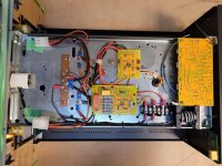
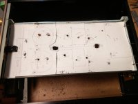
After assembly of the PCB I had to start working on the chassis. First thing I did was to install a steel sub-chassis in the center as the original to mount the trnasformer/caps nad Meter PCB on top and the Input/Rectifier/Softstart PCB under, with the AC voltage selection screw terminal and the copper bus bar.
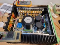
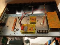
To mount the different parts I then localized all part using a paper model, then drill the mounting holes and assembled the parts. You can see the last pictures showing the current wiring progress. What is missing are the speaker output from the amp that goes to the rear binding posts/protection relays pcb on the back. The amp modules are connected using large Molex connectors, can be mounted on the side of the bench for test, and easily unplug. You can see the two large white Molex plug on the right, last picture. Before you ask the black/wire coil on the rear is my version of Ayre non magnetic line noise filter...
To mount the different parts I then localized all part using a paper model, then drill the mounting holes and assembled the parts. You can see the last pictures showing the current wiring progress. What is missing are the speaker output from the amp that goes to the rear binding posts/protection relays pcb on the back. The amp modules are connected using large Molex connectors, can be mounted on the side of the bench for test, and easily unplug. You can see the two large white Molex plug on the right, last picture. Before you ask the black/wire coil on the rear is my version of Ayre non magnetic line noise filter...
Attachments
Last edited:
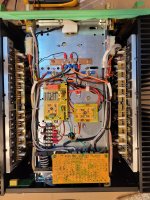
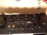
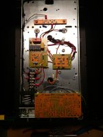
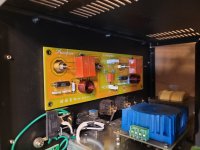
This is the rear panel pcb with the protection relays, zobel and the small realy used to bridge the amp. You can also see the blue transformer. This is an extra transformer I made to supply the amp section AC used to produce the +/-85V used by the amo front end. There is one secondary per amp channel. The amp has local discrete +/-60V regulator and simple 7818/7918 regs for the servo opamp. The original has custom binding post made for Accuphase. I installed Furutech large binding post. They match perfectly the output PCB layout.
Here also the amp module under testing. There is no feedback at the moment, since the normal feedback includes the front end PCB, but the amp module is working fine under resistive load, with a gain of 15dB.
Here also the amp module under testing. There is no feedback at the moment, since the normal feedback includes the front end PCB, but the amp module is working fine under resistive load, with a gain of 15dB.
Attachments
Success so far, after 3 days of assembling the amp, doing the wirings, checking functions. All is connected and checked except the various front leds indicator, and the meters. There is 136 crimps connectors pins to do to wire everything. Don’t worry there is only 4 per channels for the audio, there rest is functions, protection, grounding, meter, leds, etc…
All supplies are ok, main amp +/-75V, front end +/-85V (from separate transformer) and amp module local +/-60V from local discrete regulators and +/-18V servo opamp supply, Meter/protection +/-24V (from separate transformer), that then goes back to the input PCB and local +/-18V for local voltage gain op-amp and BAL to SE converters. A lot of supplies all over the place, it was the first thing that I had to figure out with the parts I had, without the Accuphase custom power transformer…
Everything is working so far: protection controls rear speakers protection relays, open if excess of dc output, or overheat, numerous functions of the input card (selectable gain and BAL/SE from front panel switches, Dual-Mono and bridge modes), Soft-start controlled by the meter/protection pcb.
Presently under test at the normal bias of 20mv at the bias TP, as recommended by the service manual. That equals to 21ma per output transistors (9 NPN, 9 PNP per channel), so 191ma under +/-75V power supplies or 28Watts dissipation. With the huge heatsink, with no signal they are still cold.
Measurements to follow, the amp modules were already tested under 1Vac/ 8 ohms on the bench.