How to glue your gas pipes without glue...

Was out for a walk and found this left behind after some roadwork by the local energy company.

When I'd got it home I realised what was going on and thought it was pretty cool.

Or hot, unless you leave it a minute to cool...

Attachments

  • 20230208_091843.jpg
    20230208_091843.jpg
    355.7 KB · Views: 178
  • 20230208_091903.jpg
    20230208_091903.jpg
    344.6 KB · Views: 172
  • 20230208_091930.jpg
    20230208_091930.jpg
    352.6 KB · Views: 178

Using ARTA while streaming music on the same PC?

Hi

Im assuming this is a common problem, but I dont think I have ever seen it described here.

I have a single Win10 PC on the workbench. I use it for background music (often streamed from radio or YT) and for measuring with ARTA.

On rare occasions it actually work doing both at the same time: using 2 soundcards I can listen to music on the speakers AND measure at the same time.
But often something goes wrong and ARTA will display some error-message when I try to start a measurment.

The problem was the same on Win7 and with a number of different soundcards.

Do you have any experience with this ?

Kind regards TroelsM

Nakamichi CD Player 3: "plays" fine, sound absolutely trashed, what do?

Recently I've got a Nakamichi CD Player 3, the MusicBank kind. The seller said it was not opening the tray and thus playback was untested and they were giving it away for a decent discount. "Aight just a few new belts right?" — the famous last words before I turned my desk into a lab first time in a decade again.

Linking the service manual right here for those kindly playing along at home: ElektroTanya

So, indeed, first I went ahead and swapped the belts and lubricated all the plastic parts. One of the cogs in the optics lifter mechanism had some crud somehow make its way onto the rod so that had to be reseated.
Then it turned out the lever of the home position sensor of the stacker assy was broken off — so I bent the spring beneath it to account for that, finicky, but it works most of the time for now.
Powering it on revealed that sometimes it would glitch out, showing garbage on the screen or trying to spin the disc in reverse up to takeoff speeds. Tapping the +5V logic supply voltage regulator often fixed that by triggering a reset. So, reflowing that and the two transistors generating the ±5V supply for the DAC got the voltages steady and spot on within a few hundred mV of the designed value. (Those components went hot enough to slightly brown their surroundings on the board)

I took out a few caps at random on both the main and RF boards and they all matched the label, albeit I have to admit I didn't look at the ESR too much.
(Cue the Benny Hill chase soundtrack and footage of myself spending a whole day looking for the transistor shaped "turns-out-it's-a-fuse" that I've blown by shorting one of the caps by accident)

Then I plugged in my speakers and put in a pressed album and... the sound was absolutely trashed, as if only one bit of the DAC was working.
I assumed the DAC is broken, so I recorded a CD-R with a few sinewaves and a silent track, 30 seconds each.

And here's how the 1kHz sinewave, 50% FS looks like on the output:
4agHk.png

Not quite 50%, not quite sinewave, but at least both channels are the same, so it's not like the DAC is faulty — I doubt both sides of it would've developed an exact same failure. It's more like something is loading garbage into it.

So I went on to play silence, and:
f1RcK.png


Definitely not silence either!

So, going on the path from the rear jacks backwards I traced along the following symptoms while playing the silence CD-R:
  • Output filter OpAmp: just repeats the noise that the DAC sends into it, once the DAC shuts up there's no noise, so it's ruled out
  • DAC: sends out the abomination on the second picture above on the L and R outs, and the input data line gets some blips of '1' bits at times, while I assume silence should be all '0'? Sure enough, shorting the data in to ground makes it shut up. The output waveform is somewhat like this:
    1677992232780.png
  • Digital filter / Resampler: Gets 1-2 of '1' bits every now and then on the data in line. Shorting the data in line to ground makes the whole downwards chain shut up, so I assume the Resampler is getting garbage data on the inputs.
  • Sony DSP chip: the CRC incorrect flag line raises 1-2 times at a similar timing to those 1-2 '1' bits. (I don't have a second probe on the scope to compare)
  • All the other frequencies seem to be spot on, aside from the PLL — it's constantly 0.2MHz too high, but locks on to the specced 4.2ish MHz just fine once the CD is spinning.
At this point I started to suspect the optics or whatever surrounds them... But that doesn't line up with the fact that it's clearly reading out the disc's TOC, and even on a CD-R, unlike many of my other players of the same era.

Easier done than said, I go ahead and try to look at the eye diagram on the RF input of the main board (while realizing the afterglow mode on my scope doesn't clear itself up over time), and this is what I see on a pressed CD:
1677992379609.png
1677992387207.png


Then I go onto a quest of re-lubricating the spindle motor bearing (a drop of IPA [not beer] into it, followed by some power tool oil), cleaning up the clamps, and attempting to make the eye diagram a tad better by spinning the EF SIGNAL knob, resulting in this on the pressed CD — that's as good ad I could get it:
1677992509938.png
1677992516831.png


But if it ain't broke, I fixed it! It won't really lock onto a CD-R anymore:
1677992546883.png

(in case of track 5-6, so 2.5-3min into the disc, it sometimes does play, but intermittently)

So now, the questions:
  1. Am I right in the assumption that the DF/DAC/OpAmp are likely all good?
  2. Could the Sony DSP chip fail in a way that it reads out the data fine but sends out garbage on the audio out? Are chips even likely to fail in the first place?
  3. Could it be the playhead having some crud get inside it and ruining the read out signal and should I replace that?
  4. ...Or am I dumb and those graphs just scream "I NEED A RECAP" about the main board? (The ESRs on the RF board were in spec as well so that's not it)

Thank you very much for your help!

Sonus Faber Cremona

I recently acquired a pair of these and like them for the most part but I find the top end a little too polite. They are lacking some bite and sparkle that I know exist. I realize that these are universally accepted as being laid back and forgiving speakers but if I can get a little more drive from the tweeters, these speakers would be that much more enjoyable.

All of the components are functioning properly.

Has anyone ever tweaked the crossovers in these? I came across a schematic but unfortunately no component values are indicated and I don’t how accurate the drawing is either. If a minor and reversible mod can be made in how the tweeter is attenuated, I would be willing to do some experimentation.

NO-VALUES-Cremona-Crossover.png

  • Poll Poll
Which 15" coaxial driver?

Which 15" coaxial?

  • 15cxa400fe

    Votes: 1 33.3%
  • 15fcx76

    Votes: 2 66.7%
  • 15cxa400n

    Votes: 0 0.0%

I have been doing some research on the 15" coaxials. Specifically those with a built in horn for the HF. My idea is to eventually replace the plastic horn with a wood biradial horn.

Anyways, so far it looks like these 3 are in the front runner.

Will be either a BR, or onken type of enclosure. Passive crossover initially.

I am looking for some input and also any additions to this list.

Thanks!!!!

Richard
  • Like
Reactions: behappybevegan

AC power relay misbehaving

A buddy has an older SimAudio Celeste power amp. He accidentally shorted the speaker terminals on one channel. He replaced the fuse but now it won’t stay on and the AC power relay opens within seconds of power up. Any idea what in general could cause such behaviour? Can’t tell if the channel with the blown fuse works as he says it shuts down too quickly to tell. Thanks.

For Sale Parts to build the BA3 Amplifier

I started to source everything to build a BA3 amplifier, but decided to go a different direction. I am selling everything for under what I paid and I stuffed a majority of the parts and sourced different parts recommended by 6l6. All you really need to finish this amp is the chassis, transformer, Mosfets, wiring, and the back panel parts kit.

List of everything included is below:

-BA3 front end board mostly stuffed
- P+N Quad of 8.7ma Toshiba JFETS from Punkydawgs (ebay seller)
- 10uf Audio Research Caps from Peter Moncrief
- IRFP9610 and 610 Mosfets along with the heatsinks (does not include screws, nuts, or Sil Pads)
- 1k and 500 ohm trim pots for P1, P2, and P3 (recommended1k for the above mosfets)
- BA3 Output and Bias/DC Offset boards
- 2 output boards stuffed with 1 ohm 3W and 150 ohm resistors (Mosfets NOT included)
- 2 bias boards stuffed with changes recommended by 6l6 in build guide (12k in R25 and 500 ohm Trim Pot in P2)
- PSU and Diode Bridges
- PSU board stuffed
-Eight 4700uf 50V caps per rail (75,200uf total)
- .47uf MPC71 Futaba 5W resistors (5 per side)
- Diode boards from the diyaudio V3 Power Supply board with MBR20200CT diodes and heatsinks (no hardware or sil pads)
- Soft start relay board (97% stuffed)
- Missing one diode D5

I paid almost $350 for all these items after shipping. I am asking just $300 and I will ship for free anywhere in the continental US via USPS flat rate.

Shipping from Houston, TX.

Cheap, temporary midwoofers for Heathkit/Altec 811b horns and 401-105 drivers

Hi All,

I just purchased a set of Heathkit/Altec 811b horns and 401-105 drivers (I think they were parted out from a Heathkit AS-101).

Eventually, I'd like to use these to put together something like a Valencia, Model 19, or A7 clone, but I can't afford genuine Altec woofers right now.

Is there anything fun and cheap I could build so I could at enjoy these horns/drivers until I can save up for the real deal woofers?

I was thinking of getting a mini-dsp anyways, so bi-amping and experimenting with crossovers is an option.

Thanks!

Onkyo M504 connection

I have a pioneer vsx95 elite and want to connect m504 ,I'm not sure on how to proceed. On the back of the pioneer I have 4 connections for left and right front speakers. 2 for right ,2 for left. But on the onkyo amplifier it has only 2 input connections one left one right. After some searching for manuals and very vague diagrams I have no clear idea. Any advice I thank you greatly. I apologize for my noobness.

For Sale Amperex Bugle Boy ECC88 6DJ8 Tubes

These tubes have all been tested on a calibrated TV-2 tester. They look great with nice bugler logos. Big O getter. Superb scope pulls.
Quad 1 delta 1B1 95,100/65, GA4 delta OL1 92,91/65, delta 1B3 90,86/65, delta 1B3 95,91/65
Quad 3 delta 0L2 83,96/65, delta 0L2 73,83/65, delta 1A1 74,80/65, delta 0K1 77,87/65
both quads for $110
includes shipping

Attachments

  • CBS6SN7GTB.jpeg
    CBS6SN7GTB.jpeg
    538.1 KB · Views: 139

Power Supply to Feed the Super Reg

Looking at Jan's "Superregs for your signal level projects" (V2.3) article with board trace diagram, one thing that stood out visually was the heavy ground trace that runs from input to output . The question is how clean does the source power supply have to be so that noise on its return doesn't appear on the load's ground. Is there a post or article with recommendations for design?

Thinking of using PSUD, what value to put in for the Superreg's equivalent resistance ? etc. (In this case the current at S-reg's output of 15VDC is expected to vary with load signal level, from zero to approx. 100mA.)

Thanks

Attachments

GB4 for Pioneer Super Linear Headphone Amp PCB set?

171015 HPA Test Platform 2.JPG


Amazingly, after 5 years of GB3, I am still being asked for PCB sets.
https://www.diyaudio.com/community/...neer-super-linear-headphone-amplifier.328997/

You can see the latest successful build here :
https://www.diyaudio.com/community/threads/the-pioneer-super-linear-circuit.313163/post-7326342

We still have some boards left, enough to support 8 sets.
Minimum 5 subscribers / sets before we can cover our admin costs.
Same as before, each set consists of
2x PCB for Super Linear Amp
2x PCB for SL Current Source
2x PCB for Discrete Regulator Positive
2x PCB for Discrete Regulator Negative
1x PCB for SHPP Headphone Protection
1x PCB for CMoy Cross Feed (through hole version)

Price will be 500 HKD all inclusive (FOB).
Please enter your interest below in a running list.
Minimum 5 sets, maximum 8 sets.


Thank you for your interest,
Patrick

Complete Electrical Parts for Your Finished Audio/Electronic Projects

Save your time to look around for AC electrical parts for your finished audio/electronic projects.
Package includes the following parts:
2 pcs. - 6ft. 2-prong AC cords
3 pcs. - 3 types AC toggle switches
2 pcs. - Gromets for AC cord
2 pcs. - Panel mount fuse holders
8 Packs - 80 pcs. fast blow fuses
2 pcs. - AC connector/socket
2 pcs. - Speaker connectors
Whole package cost only $ 9.50
To get a shipping quote, please let me know your address and phone no.
Canadian orders pay by e-transfer.
U.S. and international orders pay with PayPal with 3% surcharge

Attachments

  • DSCN0051.JPG
    DSCN0051.JPG
    174.5 KB · Views: 65
  • DSCN0052.JPG
    DSCN0052.JPG
    187.3 KB · Views: 65
  • DSCN0053.JPG
    DSCN0053.JPG
    139.1 KB · Views: 57
  • DSCN0054.JPG
    DSCN0054.JPG
    291.2 KB · Views: 61
  • DSCN0058.JPG
    DSCN0058.JPG
    126.5 KB · Views: 67

Suggestions for first and last hifi amp schematic please

Hi Y'all,

begging your pardon. I am pretty sure this is not the first thread concerning this topic but regarding hifi-amps i am totally out of my depth and i would like some suggestions from more educated people.

I want to build an all-tube hifi amp for my little apartment but it wouldn't bother me if it could rock bigger rooms to.

I want to keep my 2-way-bass reflex speakers, i like them a lot ever since i put them on spikes.

I listen to rock, classic, pop, right now, i am using a ND304 which is a good amplifier in my book and i can tell a good recording from a bad with my equipment, i am pretty sure my setup is not top notch but good enough for me. The olde NAD needs it's relay replaced every couple of years and after 20 years it would like some quality time, it cut`s out at very low volume. Also i think i already have most of the parts i would need to build a hifi amp.

I have been building guitar amps and reverb units, that was a lot of fun and i ended up with my own designs but of course i copied parts from existing designs. I don't want to go down that rabbit hole when building an hifi amp but stick to something already existing.

It will play music coming from my computer (yikes!) but once this works i of course would need a phono preamplifier.

I think, i would want an EL95 Push-Pull output stage.

So i thought i could pick an amplifier from this list, get the schematic, replicate it and be done with it but i would appreciate suggestions on what to build, before i start.

Some questions: Ultralinear or not?

Single Ended or Push-Pull? EL95 or EL84 or EL34?

I have a big chassis i want to use and i can apply a lot of shielding, is it insane to have the phono preamp in the same chassis?

I would use what i learned about noise suppression from building guitar stuff and apply it if it is not already in the schematic. DC elevated heaters, grounding, layout, etc.

So what would you suggest?

VESA or other mounting for small speakers

I'm in process of designing a small and light weight speaker. It's getting 3D printed cabinet and while drawing it, I had an idea. I could put in mounting points for wall-mounting. The VESA seems to be a nice standard, it's got patterns sizes for small and light weight stuff too. I'm using heat-set inserts for screw holes, that should provide enough strength to carry small speakers. There are many wall-mount arms to choose from if I want to hang my speakers onto something.

This spawned another idea. Should I still put them on the bottom plate? The load would be lower on the cabinets plastic, but this will rule out some booms. On the other hand, a good arm will rotate wide angles and the weight is low so should not be a problem.

What do you think? Is there some other standard I should go for?

I was also thinking of mic screw size, but that's a single screw so I don't trust that PLA holds. It would need a stand where the screw stops it from slipping, but it would rest on it's feet.

Anyone need a microcontroller chip for their Golden Tube Audio SI50?

Bought this unit (GTA SI50 MKII) with entire control system (bias LEDs, input select, power LEDs, Remote Volume Control, etc) not functioning - so I bypassed it, and worked great.....well that as a few years ago...

Finally got back to the real fix - that known microcontroller issue - anyway, found the hex file at Yahoo Groups and programmed a new - blank PIC16C72-04/SP chip, and now front panel control all working again...anyway, I burned three, only needed one (these are write once - OTP - microcontroller chips, and I anticipated problems...bah). Let me know if you need one...the chip cost me $4 from digikey...

This is for the SI50 MKII, not the SI50 MKI (the MKI controller hex file is also on the Yahoo site)...
  • Like
Reactions: analog_sa

Distribution of the Voltage Gain Factors between Line Stage of Pre-Amplifier and Power Amplifier

Actually the answer is simple, if one keep in mind, that several integrated amplifiers like the good known Luxman L210 don't use an active line stage (preamp section consists only of an input selector and attenuator for volume control):
only unity gain for the pre-amplifier (i. e. only a buffer to transform the impedance to drive all kinds of signal leads) and factor 30-50 for the power amplifier.
In real life I note at nearly all commercial tube and solid state pre-amps gain factors around 10.
As a result, the total gain factor is around 300-500 with the problem that the maximum undistorted level is reached shortly after the zero position (under certainly conditions speakers blown away).

Under
https://www.tubecad.com/2009/03/blog0161.htm
and
https://web.archive.org/web/2007010...m/tubecircuits/Tube_Line_Stage_Amplifier.html
I read this (concerning only line stages):
Just how much gain is needed for a line amplifier? Let's begin the answer with the observation that most line amplifiers have too much gain.
Working on the assumption that even the world's most inefficient power amplifier needs only 3 volts of drive signal to be driven to full output and even the weakest tape deck or CD player puts out at least 0.5V of signal, the greatest amount of gain needed would be 6:1 or 15 dB of gain.
Yet most tube line stages have between 20 to 30 dB of gain (10:1 to 32:1).
While this extra gain impresses the audio neophyte who marvels at the power implicit in the distorted thunder that a mere one quarter twist of the volume knob provokes, it ultimately only subtracts from the useful range of turning on the volume control and usually only worsens the signal-to-noise ratio of the line stage. (Remember, many audio systems don't use any active gain line stage—zero gain—and rely on only passive attenuators and switches to connect line level components to the power amplifier.) If 20 to 30 dB of gain is too much, how much then is best? The answer will depend on each system. (This is the answer most hated by dogmatic audiophiles who seek absolute answers to relative questions...) A safe guess, however, would be 10 to 20 dB of gain, which translates into 3 to 10 times the input signal.


This means, due to the lack of clear guidelines regarding the distribution of the gain factors, everyone of the manufacturers does what they think is right.
Because the overall gain was too high, I often had to intervene in the devices (mostly in the pre-amplifier line stages) in order to reduce them when I was a hi-fi dealer in the 90s.
Always on Moth' active preamp - go to
http://www.stancurtis.com/downloads.htm
this was absolutely necessary in order to use the volume control usefully.
It was very unpleasant to have to modify new devices in order to sell them to an interested audiophile guy.

But what actually is the best gain distribution in order to get best sonic performance ?
Some people think, power amp should be only unity gain character and the pre-amplifier should have the wanted resp. necessary voltage gain.

In real live this is the absolute exception - the only unity gain power amp I now are Andrea Ciuffoli's Power Follower DIY projects - go to this URL's:
https://www.diyaudio.com/community/threads/quality-in-a-cool-follower-99.12542/
https://www.diyaudio.com/community/threads/andrea-ciuffolis-power-follower.3471/
and similar projects mentioned in post #11

  • Locked
For Sale SEAS Exotic drivers

For sale are the amazing seas exotic drivers.
X2 08 8ich high efficiency woofer
X3 06 high efficiency tweeter
In lovely condition and not driven hard.
Reason for sale is a hard decision tbh.
I also have some large horn speakers, and cannot have both in the living room, and don't have anywhere to store them safely, so they have to go.
Currently in a cabinet (excluded)
Dont have original packaging, as I bough them second hand in the cabinets, but will be wrapped securely for transport.

Woofers £715.00
Tweeters £420.00

£1,000.00 if bought all together.

Ex post.

Attachments

  • 20230924_133758_compress91.jpg
    20230924_133758_compress91.jpg
    590.4 KB · Views: 170
  • 20230924_133808_compress90.jpg
    20230924_133808_compress90.jpg
    597 KB · Views: 179
  • 20230924_134026_compress41.jpg
    20230924_134026_compress41.jpg
    327.3 KB · Views: 144
  • 20230924_134045_compress95.jpg
    20230924_134045_compress95.jpg
    382.4 KB · Views: 143
  • 20230924_134050_compress14.jpg
    20230924_134050_compress14.jpg
    425.8 KB · Views: 184

Newbie and an Isolation Transformer

I've purchased a used isolation transformer from a well known brand. Inside the case are two toroidial transformers (Youwon DV-130-1), on the back of the case are two duplex receptacles (each going to a transformer). There is a circuit breaker on the back and a power switch on the front. The transformers primaries are BROWN/BLUE, and the secondaries are BLACK/WHITE. There is a GREEN coming out of each transformer, and per this thread, I believe that this a shield internal to each transformer. Each receptacle has a ground wire leading to a lug on the chassis that has mains ground as well as the green secondaries (shields) on it. The neutral on one receptacle had a green wire also going to this lug. I thought I'd be clever and remove the receptacles ground wire that goes to the chassis ground (as well as that neutral secondary to chassis ground). I've verified there is no continuity between the hot/neutral on the receptacles and the green secondary wire. However, I'm still seeing continuity between the ground on the recep, and the chassis. It appears that the receptacle's tabs that screw to the chassis are also ground. So I really don't have an isolated ground. I think I'll need to purchase separate receps that don't have that trait.

The other worrying thing is that when I turn on the isolation transformer, put my meter on VAC, and stick a lead into secondary hot (receptacle hot) and to mains earth or neutral, I have about 70VAC. This seems very wrong, and I must be missing something. The referenced thread sounds exactly like the device I have purchased, down to the capacitors on each recep. There also appears to be a varister on one of the receps (mdc z131 20ul).

I really don't want to hurt myself, and I do want to learn. But having 70VAC between secondary hot and earth neutral can't be right. I'm not measuring anything else. I'd love to hear some thoughts on what I'm doing wrong. Thank you!

Enclosure design - NOOB

Helloo! I am a noob with DIY subwoofers but I wanna build 2 subs 15 inch. The subs will be used for playing music and for bands (drums and bass) for wedding purpose. Because I own a small car and I am alone I need to find 2 compact, lightweight subs (30-35KG MAX) with goes at minimum 38Hz. I saw that Beyma has an enclosure design for 15LEX1000Nd that is quite compact but i dont know if its ok for music and bands. I saw than the Nexo LS600 enclosure but i dont wanna copy their design.. Some drivers that I found cheaper in my country but i dont have enclosure designs:
BC 15TBX100 / 15TBW100 / 15NW100
Beyma 15LEX1000Fe
Faital 15FX560

If you have something to recommend (driver and enclosure) I would be very grateful. Thank you very much!

Fidelity of DSP crossover at high frequencies

Howdy folks

I've got sort of a strange query. Really interested in getting some thoughts from you all

So, it seems to me to be an ongoing conversation on the whole "DSP vs passive crossover" debate, and the solution some have landed on is one that I find very intriguing; that is, a hybrid crossover that utilizes both.

In such speakers, you typically see a passively filtered mid and tweeter, with a DSP filtered woofer.

There are many reasons for such an implementation, but among them is that we are allegedly less sensitive to unwanted digital transformations of the signal at lower frequencies. A term I often hear thrown around in these contexts is "digital artifacts". My experience with DSP is limited, but the argument seems to me to go like this: "While DSP offers more refined tuning, the overall fidelity still does not match that of passive filters. There is a subtle but unmistakable tonal character imparted onto the overall sound when digitally manipulating the signal (another term I hear is "digital sheen") that makes passive filters still the best option at the highest levels of hifi". (This is not to suggest that passive crossovers don't also add their own little flavor, but I guess the argument goes that it's less objectionable in this case)

Now, I don't know if this is true, but let's just say it is. Some people take this idea and say, "ok, but any timbral anomalies will not be audible, or at least perceptible at lower frequencies", thus, hybrid crossovers.

I have 2 questions. My first is this: why? Why can't we hear traces of DSP at lower frequencies, yet we can at higher ones?

My guess is that it's because the woofer (let's just say it's only playing 300Hz and below) is outside of the critical range that really defines the timbre of music.

So here comes my second question. If this is true, (and I'm not saying it is), could the same concept also be applied to the extreme top end? Would you still be able to detect this digital sheen in a speaker that's mid is filtered passively, with a tweeter filtered via DSP? Let's say crossover of 7KHz.

Why exactly you would do this? I don't know. I can think of a few things, but it's definitely a weird idea with few use cases, presupposing that it's a sound idea at all

Anyways, I am eager to hear your responses. Thanks to those that read through all of this

Frequency drift in Sony tuner(s)

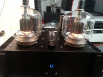
Some time ago I had posted a thread about adjusting a St-S370 Sony tuner. At that time, the unit would show "100.00MHz" and in reality it would "tune" to 98.50MHz, which I had "fixed" with NULL adjustment. Unfortunately after some months of not using the unit the same problem re-appeared: the unit would not light the "TUNED" indication, no stereo indication, no auto-tuning and no RDS. I had read that gravity sometimes was the cause, but I realized that in my case it was not the problem (as this time i had to turn it even "lower" to re-align). Also it was VERY temperature sensitive (on a hot evening it would not "TUNE" or auto-tune, if it was adjusted the previous cold morning).

The solution (so far) was found by accident when trying to solve a problem of another Sony tuner (St-sa5es this time). I came across a 
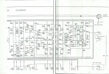
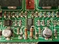
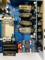
german page in which the solution was described as being a problematic capacitor soldered inside the legs of the T252 (NULL adjustment can). When I unsoldered it to access the capacitor, and tried to remove the metal can cover, the capacitor was desintegrating in my hands, and in the end it broke literally in dust, with a simple "touch" of a plastic screwdriver. I believe breaking it is the best way to remove it as the plastic of the component is also very old and sensitive to crack while removing the cover. This means I didn't have the chance to roughly measure the actual value of that capacitor, so I used 2x47pF C0G capacitors in parallel (I tried to be close to the 91 pF, the value mentioned in that webpage). I soldered the capacitors outside the can (in fact I soldered on top of the board, across a resistor which connects to the same pins where the capacitor was soldered, as I wanted to experiment with freezing and heating the capacitors). After that, a very slight NULL adjustment was needed (which indicated the faulty capacitor's value was not very different than the 94pF I used) and now everything seems to work as it should. No drift of frequency even when using hairdryer and then freezer on the capacitor (and the T252 can). I am now waiting to see what will happen in the long run, but I believe this is the definite fix, as before I had slight problems from day two (drifts when using the unit cold until it heated a bit and would "TUNE").

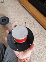
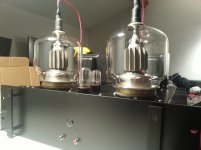
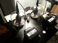
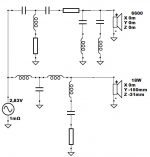
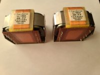
And now a bit of information I wanted to share about a ST-SA5ES I bought, which would not auto-tune or display RDS data. The first thing to try was again NULL adjustment. I then realized that the IFT272 (IF transformer which is the adjusting component in this unit) was stripped and it was impossible to move up or down the ferrite core by turning it! Also there are no specs anywhere on the internet, so my only chance was to buy a new plastic frame and wind the transformer myself, following the winding of the original).
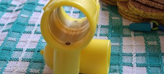
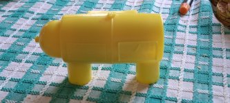
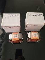
So I ordered from aliexpress and empty container for the "stripped" can. The most relevant I could find was "K175 High Frequency Radio Transmitter Receiver Adjustable Inductance Coil Skeleton Kit Accessories" (5 "floors" in bobbin, 7+7x12 cm, core 3.2x5 , it is a bit taller than original).

I have to note that this has 5 pins (3+2) so I had to insert an extra pin on one side (original has 3+3 pins on)
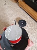
How to wind it: (I used original thin wire which was unwound the reverse order from the instructions below):


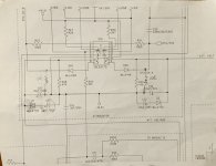
(When I say "floor" I mean those showed on the next pic, where I number 5 is the topmost and 1 the lowest - NOTE: the pic below which I found has 4 "floors" instead of 5):

6BDEJ9J1lSoVFjDx.png


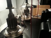
Side1 (with pins 1 to 3 from left to write): solder fine wire to left pin 1 and wind to the 3rd floor (middle of 5 floors) clockwise (looking from top) 4 times, then solder to middle pin 2, wind another 4 turns again to floor 3 and solder to the right pin 3.


Side2 (pins 3,4,5): solder fine wire to left pin 3 and wind 3 full turns clockwise (looking from top) to the lowest (1st floor), then another 3 turns to the 2nd floor, another 3 turns to the 4th floor (we skip 3rd floor) and finally 4 turns to the top (5th) floor, then solder to middle pin 4, then wind another 3 turns to the lowest 1st floor, 3 turns to the 2nd floor, 3 to the 4th and 4 turns to the 5th "floor", then solder to right pin 5.

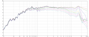
After doing this, without using the external metal can enclosure, I could "tune" the discriminator with the iron core near the bottom of the bobbin (I used the new aliexpress core, not the smaller original). After adding the metal enclosure, the tuning point was close to the top. (When adding the supplied magnet cup, I could not fine tune as it was a over the top of the bobbin and I was out of turns - so I didn't use magnet cup).
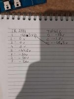
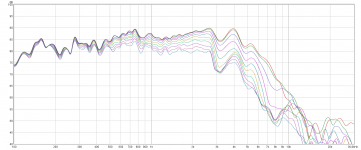
Having done all that, I was able to get back tuning (TUNED and STEREO indications) and RDS recognition, and then I realized the tuner was 100kHz out (100.4 on display was actually 100.3), which I corrected very easily using the method in service manual (adjusting IFT251 to zero across the resistor that connects to pins 7 and 10 of chip 251).

As I checked it is also temperature stable, 3 weeks from adjustment nothing has "drifted", and also auto tuning works normally.

Sorry for the very long post, I just wanted to explain how to wind a "compatible" IFT272 as there is zero information on that on the internet (and this type of circuit is used in most top of the line Sony tuners - 707ES, 770ES etc.) I thought someone might need it in the future... And I wanted also to share the problem with temperature stability, which I think occurs quite frequently as those tuners are now old and many used similar cans from the same manufacturers so they might experience the same problems sooner or later.

Budget high sensitivity proven designs

Hello all,
I wonder why there is no high sensitivity proven designs or kits available. I looked everywhere in parts express catalog, madison, css, gr research and others without little success. Css has a mtm that they claim is 90 spl, but its a grand for the kit. Madison has another mtm kit, but I couldn’t find any reviews on it.

So my questions is why do are so many kits especially the budget kits 84 to 86 db? Is it that there are no good quality drivers that are also sensitive?

Kenwood KA8011 VU meter

Hello,

I have a "problem" with the VU meter on the KA801 amplifier. When I turn on an amp VU meter needle on the right (sometimes on both) channel jumps a little before the speaker relay engages. I know that is not a serious problem, but it is irritating. Aside from this problem, the VU meter works well. There is a TA7318P driver.

I check voltages, there is no input voltage before relay click. But there is voltage on output when I turn on the amp (before relay click), the left channel jumps to 7mv and then to 4mv. Right channel jumps to 13mv and then falls down to 4mv. This causes a jump on the VU meter.

When speakers are disconnected it jumps more. I have no clue how the speakers can affect when the relay is not engaged.

Can be something wrong with ta7318P ? Thanks a lot

Attachments

  • ka801.png
    ka801.png
    397.3 KB · Views: 76

Arturo Delmoni & Stephen Martorella, Beethoven sonatas live (and free!)

<iframe width="560" height="315" src=" Login to view embedded media " title="YouTube video player" frameborder="0" allow="accelerometer; autoplay; clipboard-write; encrypted-media; gyroscope; picture-in-picture; web-share" allowfullscreen></iframe>

Save the date (as long as you are in the Northeastern US):

Sunday November 5, 2 PM at the First Baptist Church in America, Providence Rhode Island.

Arturo Delmoni & Stephen Martorella will play Beethoven's "Kreutzer" and "Spring" violin-piano sonatas, a "surprise" piece, and perhaps an encore or two.

Free and open to the public; a goodwill offering can be made afterwards.

The venue is a famous historical church with its original 1775-vintage horsehair-plaster barrel-vaulted ceiling, and therefore, good acoustics.

The above video was shot there.

I hope to see some of you there!

john
  • Like
Reactions: brianco

IR2011 class D issue

Hi
Amp is based on IR2011. No output switching, The Ir2011 is a brand new one from a reputable source.
I do have proper square waves at HIN/LIN but it's like the chip is in shutdown mode or do not have the proper voltages at Vcc,Vb,Vs.
There is a small schematic - D667 + TIP41C, resistor and two diodes supplying the voltage to pin 1 of the IR2011. The diodes have been replaced by a previous repair attempt and i'm not sure they are the right ones.
I did check the bootstrap diode + cap, all fine. The circuit is almost 100% the same as in the datasheet for Infineon-IR2011.

Any reference with the correct voltages for ir2011 would help.

Attachments

  • 1.jpg
    1.jpg
    576 KB · Views: 237
  • 2.jpg
    2.jpg
    279.8 KB · Views: 183

Is Fullrange my best bet?

Hello

im strongly thinking going with single Fullrange drivers since i think it has some nice advantages which would be:

1. point source, its also a PC setup, currently i use Presonus Eris E8 studio monitors
2. linear phase(?), i have to include here that the Presonus wire the tweeter 180° out of phase compared to the woofers and imo this is audible, i can switch polarity and hear either forward bass or forward highs (both sound better then the "backward" sound of out of phase but i cant have both with my current speakers... and also many others)
3. easy to drive, there only need for a stereo setup in terms of dac/amp channels (if i wanna go active)
4. not really a crossover needed, for me this is one phase altering can of worms i dont really wanna go into, i can dsp with FIR equalizers instead, so the chain is as pure as a wire going from amp to speaker 🙂 (i would also use something like pure copper terminals on the speaker and some nice ofc/occ copper/silver cable
5. price, apparantly there are very good 100€ per driver speakers, which would probably not exceed 500-700€ for a pair, for this price im also willing to "just try it"
(yes, generally speaking i come from a "audiophile/audiophool" standpoint here for some, but generally speaking i think full range speakers will decomplex a system greatly)

what you guys think about these advantages? do you agree? what about disadvantages? doppler effect etc? im also wondering why in studio setups there are rarely full range speakers

ultimately i wanna have a full range + subwoofer setup, the full ranges should go down to 50-70hz and 20khz high, more is appreciated

i came up with these speaker https://www.markaudio.com/wp-content/uploads/2023/07/Toco.png what you guys think? imo closed is a must have, i dont wanna go BR and i also dont like it on my Presonus... it makes male vocals "lose/inaccurate" sounding imo
  • Like
Reactions: hm

High power GU46 SE amplifier - help with certain issues

Hi.

I have recently completed (well, almost) a gu46 based amplifier.

The specs are the following

6sn7 + 6sl7 (ccs laoded) two stage cap coupled driver
gu46 in pentode mode (1500v anode, 650v screen)
DC heating for all tubes
5k SE Hammond transformer (100mA bias per tube).

The gu46 works but I have a couple of questions.

1. the driver was designed based on the assumption that I would need GNFB. I have not had time to do a proper frequency sweep but I can tell bass rolloff is not that good. So I figure I would need some feedback.

Problem is I know very little of implementing GNFB. Would injecting signal through a voltage divider suffice? Do I need to add a capacitor to bypass the series resistor? Should the signal to inject be taken from the 4 ohm tap (used for speakers) or the 16ohm tap (currently not used)?

2. the gu46 filaments are DH of course. Unfortunately I was unable to score more than one switching transformer so I currently feed both tubes from one single supply. Is there are problem with this? Will the tubes crosstalk somehow or affect each other's behavior?

I have always used separate psus and haven't had the chance to test both channels of this new gu46 based amp at the same time so I figure I'd ask you guys while I can still find a solution.

Thanks

Attachments

  • 20141225_194036.jpg
    20141225_194036.jpg
    640.6 KB · Views: 1,169
  • 20141225_194047.jpg
    20141225_194047.jpg
    567 KB · Views: 1,108
  • 20141225_194059.jpg
    20141225_194059.jpg
    513.7 KB · Views: 1,049
  • 20141226_095335.jpg
    20141226_095335.jpg
    518.3 KB · Views: 1,046

Power amp OUTPUT STAGE measurements shootout

Let's try new ways to measure the distortion of power amp output stages, with inspiration from the Gedlee metric. This is the concept:

schema.jpg

How it works

The DUT, output stage under test (here, the usual push pull) has its bases driven and biased. Its output is set to 0V at DC.

Current is injected into its output by the two drive amplifiers on the right, via the associated resistors.

LF amplifier channel outputs a large low frequency signal (0.5-1A, 40Hz) which sets the "DC" operating point of the DUT, basically the current in both transistors.

HF amplifier channel outputs a high frequency low amplitude current (few mA, 20-40 kHz), which is injected into the output stage.

A bunch of high performance instrumentation amplifiers (AD8421) monitor voltage in interesting places:

- output voltage
- output current (for verification)
- emitter resistors to measure current through both transistors
- base resistors to measure base current
- Vbe, if needed

Implementation

setup.jpg

Control: STM32G0 (12 bit ADC), and 4 channel 12 bit I2C DAC, with amplifiers.
Current drive amp: Modulus-86 with DC servo deactivated on one channel.
DUT Base drive: 2 channel TPA6120 composite.

The base drive amps and the high current drive amp are controlled at DC by the micro and DAC, and AC coupled with the soundcard, so they can output DC plus AC signal.

DUT bias current can be set either directly (if both bases are driven) or via the usual Vbe multiplier, which is controller by an optocoupler. In both cases, the micro can set and measure the bias current.

Soudcard: Steinberg UR-44C (4 out, 6 in, 24b-192k)
Power supply: 2x programmable KD3005P 30V 5A

Since all parameters are controlled, 4-quadrant testing is possible: for example the output stage can be driven by a sine wave, and its output current by a phase shifted sine wave, which can emulate any reactive load impedance. Additionally, the power supplies are controlled, so behavior can be investigated over the whole Vce/Vds range.

The whole thing is scripted with python.

Empire 999 RE/X mounting bracket

This is probably a forlorn hope, but I'm trying to find a mounting bracket for an Empire 999 RE/X cartridge. It looks to be the same body as the rest of the 999 and 2000 series.
Either the metal or later plastic version would do the trick, but they seem to be like the proverbial rocking horse droppings.
If anyone has any idea where I could obtain one, I'd be most grateful.

Hartke HA3500 Fet power stage

Attached you will find the power section of the HA3500 bass amp with the Fet powerstage.
Not so great, but it will do.
After some trouble to get it back to work it sounds very powerfull and clean.
Allthough, the heatsink becomes a bit to hot to my liking after 10 minutes of playing.
I do not have much experience with fet power stages and I wonder what the iddle current should, must be.
Adjusting the trimmer VR470 dosn't do much.
Any hints, very much appreciated.

Attachments

  • Eindtrap.jpg
    Eindtrap.jpg
    372 KB · Views: 248

Leaking electrolytic capacitors nearly destroyed my old preamp - A cautionary tale

About 5 years ago I had a problem with my Rowland Consummate preamp. DC on the outputs.
I contacted Rowland about the problem. The preamp has a separate power supply enclosure, and the power supply measured within spec, so it was assumed the problem was in the potted gain modules, which were no longer available. The preamp went into storage.

About 3 years ago Jeff was able to find some old gain modules, which I gladly bought. Sadly, the problem that seemed to go away came back soon afterwards. The preamp went into storage again.

Since I started diy about 10 years, I am (very, very) slowly understanding how some simple circuits works. Also, reading the experiences of other diyers has been great to gain a better understanding of what does what, and why and how. Anyway, I had a feeling the electrolytic capacitors (1993 vintage) might be the cause of the problem. I opened up both enclosures to take detailed photos to find out the specifications of the original caps used. I needed this if I was going to find replacement capacitors (there is no service manual or schematic available to my knowledge).
What I found when I zoomed in on one of the photo's in particular was what I assumed was a leaking capacitor.

Long story short, yes there were a few leaking capacitors. They had been leaking electrolyte and it looked like they had damaged a few tracks on the pcb.
leaking capacitor.jpg
leaky capacitors.jpg


Knowing I was out of my depth and not wanting to damage such a rare and beautiful preamp, I found a technician with lots of experience. He removed all the electrolytic caps from both pcbs and was able to clean up the boards for me.
IMG_20230906_144504329.jpg
IMG_20230906_152007403.jpg
IMG_20230906_152210357.jpg


With the aid of photos sent to me by someone who had just recapped his own Consummate, my technician was able to reconstruct the damaged tracks of the amplifier pcb and replaced all the caps for me.

After 5 years, I am once again listening to a great preamp!

If you have vintage gear, please check for leaking electrolytic capacitors. Don't wait until the leaking electrolyte eats away the tracks and causes damage that cannot be repaired
  • Like
Reactions: Eric

Left Channel Issue AKAI AM32 Amplifier

Hey,


Hoping someone can give me some help 🙂


I have an AKAI AM32 amplifier ( schematics link here : https://elektrotanya.com/akai_am-32.pdf/download.html , also attached ) and am having an issue with no output out of both the left side speakers. Also no output on the left side of the headphone jack. Have opened it up and given it a clean ( was very dusty ) and had a look at most solder joints which all seem to be in tact. The amplifier was left on for an extended period of time which may have contributed to the issue. I have checked the fuses and none were blown. Was working perfectly fine the day before and have been using regularly for the past year.


I have a voltage meter and a soldering kit. I have some previous experience with electronic but not a great deal with amplifiers.


Any help appreciated 🙂))


Thanks,


JB

Attachments

ClassIllu - Scan Speak 2way, tilted baffle

After few larger, 3way projects, with Bliesma tweeters, I wanted to build something easier, smaller, yet still providing reasonable bass extension and sound quality. 18W/8545K00 and 6600 were already in house, on the shelf, and these drivers definitely deserve better then just staying in the boxes.
Woofer alignment modelling was the first action, also reading and studying 3rd party measurements and experiences. This driver model well in 15-30liters BR. This project was meant to be standmount 2way, so I wanted to keep volume on lower side. Moreover, few experiences told me larger volumes and trying to achieve as low extension as possible do not provide good subjective bass quality. So I ended up with 16liters enclosures.
18W Classics drivers are quite famous and already on the market for ages. Quite surprisingly, there is not much projects, measurements, experiences and sound descriptions on the internet. From datasheet FR it was clear they are not as linear as one would wish so I was prepared for the fact that crossover work would be more difficult here. Measurements confirmed that and I used acoustic LR4 slopes at 1650Hz to get geed off axis set of FRs and phase matching.
Initial crossover was little bit bright in 2-10kHz area, and I expected, based on 6600 measurements, that I will have pay more attention to this area and make adjustments by listening tests.
I have to say, after few adjustments and drivers burn-in, I am very happy with the sound. Bass quality, overall balance, details,...all is there and the sound is very much enjoyable.

Writeup and more details:
https://pkaudio.webnode.cz/classillu/

Attachments

  • 20220706_141923.jpg
    20220706_141923.jpg
    131.9 KB · Views: 412
  • 20220708_153544.jpg
    20220708_153544.jpg
    126.7 KB · Views: 407
  • ClassIllu crossover topology v3.png
    ClassIllu crossover topology v3.png
    28 KB · Views: 426
  • ClassIllu sixpack v3.png
    ClassIllu sixpack v3.png
    189.6 KB · Views: 355
  • FR 18W H 0-90.png
    FR 18W H 0-90.png
    151.4 KB · Views: 308
  • FR 6600 H 0-90.png
    FR 6600 H 0-90.png
    127.1 KB · Views: 326

Any experience with SB Acoustics' Satori AT60NC-4 Air Motion Transformer Tweeter?

One of my design partners has a general preference for AMTs vs. Ribbons. I love ribbon microphones and I love ribbon tweeters, but I listen mostly to classical music and I do not listen to music that is all that loud. My design partner loves the sound of Fountek's NeoCD3.0... as long as it is not pushed.

What we would like to know is if anyone has experimented with the Satori AMT; and, even better, compared it to the near-price Mundorf AMTU60W1.1-C Air Motion Tweeter -4 ohm. That the Mundorf claims a non-trivial increment over the Satori in terms of pushing area is at this point a major consideration.

Thanks in advance to all.

john
  • Like
Reactions: bassman_soundki

Pushing the limits of TDA1543 NOS DAC

While my commercial offering of TDA1543 NOS DAC has been quite successful (close to 400 kits and DACs sold) I wasn't really eager to modify or change anything. The DAC had couple reviews on 6moons, most recent one here: 6moons audio reviews: Audio Zone System

For good few years it was my reference DAC and I preferred it over Benchmark and Levinson 360S. Later I found out about Bidat and this become my new reference, pushing NOS DAC to a secondary system.

Few years ago I was contacted by another forum member (Bobken) who suggested some mods to my original design. I tried those mods and they improved the performance. We started email correspondence and what seemed like a trivial thing initially, turned later into 4 years vendetta of countless trials and experiments. While Bobken is still experimenting with his DAC, I'm pretty satisfied with my version and in this thread I will post all the details.

The DAC has been voiced and finalized in my friend's reference system which is highly optimized vinyl rig with 3 way active speakers. In a recent test, the system owner had hard time distinguishing vinyl from digital; the analog front end consisted of modified Versa Dynamics with double Forsell platter, custom air compressors, ZYX Universe silver cartridge and AR PH7/AS phono stages. The digital sources were either modified TL1 and TL0, plus this NOS DAC. His previous AR CD8 was later replaced by TL1/ NOS DAC combo (there was simply no doubts what sounded better).

To me, combined with TL0 and custom digital cable, this is the best DAC I tried so far, and because of it's superior performance I'm presently not really researching any new DAC designs which some of you might have noticed 😉

Needs advice on how to achieve wireless PC audio to mixer

Hi,

Here is what i am trying to achieve. You may refer to the layout map.

Host is using wireless mic connected to mixer and usb condenser mic connected to PC for zoom streaming.
1. Is there a way to stream PC sound(Music etc) wirelessly to the mixer?
2. Is there a way to concurrently output the usb condenser mic to PC and mixer(wirelessly).
*USB condenser mic has a headphone monitoring port, can i perhaps use that as a way? or recommend a condenser mic that can accomplish that is fine as well(Budget below 300USD)

USB condenser mic BOYA BY-PM500
Wireless mic lav mic(Mini XLR) to transmitter pack
1696222601551.png


Thank You in advance. Do ask if you need more information. Not an expert in AV field, will try my best to explain as clearly as i can haha.

SVS sub Indigo board repair

I have an SVS sub model 20-39PC-Plus which has failed. It powers up but no output. I'm looking for schematics and any relevant info on the Indigo boards in it, namely:
630096 Rev 0
630126 Rev 0
630127 Rev 0
640022 Rev 1
650027 Rev 2

SVS have been no help, and Indigo itself appears to have been sold to the Chinese company Sonovox and proprietary rights to the designs get in the way.

I was able to follow a bit of the layout by comparing to the Klipsch Promedia information compiled by Dale Thomson in Klipsch Promedia V.2-400, V4.1, V2.1, And V5.1 Amplifier Repair

Power supply voltages look good but the signal is lost somewhere. Without reverse engineering the whole unit...🙁

Any help appreciated.

Thanks, Don Whyte

Low Bass Outside By The Pool

Hello

We enjoy home theater out by the pool and for my birthday, the wife is allowing me to buy some subs. Since there will be water I want to tune the box as LOW as possible, like 5 hz low. I think it will be cool to see and feel the bass!

I would like to stick with 21 or maybe even consider 24 inch subwoofers. Since they will be outside I want to do a tapped or folded horn or something to protect the driver. Also I am thinking that pro audio drivers would be best suited to handle the outside heat?

Stereo Integrity HS- 24 - These look nice but very expensive and a 2 month wait! FS 16.2
HTS545HE-4 Kraken 21 - Nice the price is right - not pro audio - 18hz - FS 26.3
LaVoce SAN214.50 21" Neodymium - pro audio - fs 30
Eminence NSW6021-6 21" - nice pro audio - expensive - fs29
B&C 21DS115-4 21" - another pro audio - fs30
Really I am open to any set of woofers.

One last thing, I have neighbors that are not TOO close but I would like to keep the bass as directional as possible.

Can someone please recommend and help me with the box design since I am not so great with software?

Thanks in advance for your advice

Orchard Audio Demo Room in Rockaway, NJ - Grand Opening - October 21st 2023

Time: October 21st, Noon to 4pm
Location: 176 Franklin Ave, Rockaway, NJ 07866

Come listen to some great music and get 10% off for coming to check out our demo room.

If you have your own favorite songs, bring them on a flash drive.

The current setup is
Source: PecanPi+ Streamer
Amplifier: Starkrimson Stereo Ultra
Speakers: Soundfield Audio M1V2
Cables: Triode Wire Labs
Room Treatment: GIK Acoustics

If you use FB please RSVP here: https://www.facebook.com/events/850175626681294/

20231001_164859 - Copy.jpg

For Sale Lundahl LL1692 AM Inter-stage Transformer / Line Output Transformer

Lundahl LL1689AM P-P Inter-stage Transformer / Line Output Transformer available for sale. This is the Amorphous core version. Bought for a project but never able to finish it up. So available for sale. Asking $300 USD , will ship anywhere at buyer's expense.

Let me know if you have any questions.

Attachments

  • 20220508_192353.jpg
    20220508_192353.jpg
    231.1 KB · Views: 254
  • 20220508_193850.jpg
    20220508_193850.jpg
    238.5 KB · Views: 232

What is your opinion of Audio Research circuit designs?

I quite enjoy Audio Research equipment, especially their older stuff from the 80's. I like the build quality, and the detailed manuals and schematics. But, I don't have the technical knowhow to properly evaluate their circuit designs. I wondered if some of you smart people could share your thoughts on especially their tube and tube hybrid designs of the mid/late 80's.

(If there is a better forum for this question, let me know, this seemed as good as any)

QUAD 909

I'm currently testing my Quad 909 power amp and have ran into a problem where the circuit breaker trips before it reaches full power (140w) I've measured 32.2v (129w) and 25v (78w) across my 8ohm dummy load using a 1k sine but at 32.2v it trips pretty much straight away and at 25v it takes a few minutes, anyone have any ideas what's happening with it?

Would it be a good idea to disconnect one channel at a time and test?

Crest Audio CA9 repair help- Who added these resistors?

Hello all,
Working on a Crest CA9 amplifier.
This is on the preamp board which also has the input jacks.
I can see someone has been in here before…
Can anyone help me understand the purpose of the two 10k resistors which were added in?
If you look close, you’ll see the left one is broken away, but that happened after moving it around.
I’d really like to get them out, but I’m hesitant to do that until their purpose is known.
They are not on the schematic, but I have drawn them in on the second photo, for easier reference.
I’m guessing they bypass part of the IGM circuit, but I don’t understand this well enough to be sure.
C17 and C18 were both bad, as were C21 and C22.
Everything else seems ok, but I don’t know exactly what IC4 does.
Hoping someone here has experience with this amplifier.
BTW, prior to replacing those 4 caps, the symptom was no audio, slight hum at the output. Active light lit, and no protect light on.

Thanks in advance!

Attachments

  • IMG_1772.jpeg
    IMG_1772.jpeg
    127.5 KB · Views: 194
  • IMG_2459.jpeg
    IMG_2459.jpeg
    61.4 KB · Views: 176
  • IMG_2460.jpeg
    IMG_2460.jpeg
    324.1 KB · Views: 156

[For Sale] Elekit TU-8500 ($450)

Elekit TU-8500 Preamp

https://wallofsound.ca/audioreviews/review-elekit-tu-8500-tube-preamplifier-kit/

UPGRADED:
1. Mundorf Capacitors: Mcap Suprem * 4
2. Muses 01 OPAMP * 2

Sound is awesome and plentiful.

"Pleas, read"

1. Line 3 is not working properly.
(left channel is not heard, right channel is too low sounding)
But Line 1, 2 & Phono are working good.

2. right top corder has little scratches.


Except above things, everything is working good.
And good preamp.

No returning, Serious buying please.
Thanks.

Attachments

  • IMG_5369.jpg
    IMG_5369.jpg
    428.8 KB · Views: 93
  • IMG_5370.jpg
    IMG_5370.jpg
    379.7 KB · Views: 81
  • IMG_5371.jpg
    IMG_5371.jpg
    345.9 KB · Views: 73
  • IMG_5373.jpg
    IMG_5373.jpg
    162.1 KB · Views: 72
  • IMG_5374.jpg
    IMG_5374.jpg
    158.1 KB · Views: 70
  • IMG_5375.jpg
    IMG_5375.jpg
    188 KB · Views: 69
  • IMG_5376.jpg
    IMG_5376.jpg
    399.6 KB · Views: 79

WM8805 Replacement?

Reducing jitter on AES3 or S/PDIF is usually a very good idea. This can be done several ways.

If we stick to the PLL method for this discussion, the WM8805 does this with a built in fractional-N PLL method and gets to about a 50ps result. One of the advantages with this part is when you want to keep retransmitting in a long chain. You can grab the data and then retransmit to the next device.

I am not sure if there is another S/PDIF receiver that does this well. The WM8805 is now End-of-Life (EOL) from Cirrus.

Does anyone know of a good replacement for this technique?

Al

10-inch Satori Coax (Mofi Pointsource 10) .. close-up pictures!

Hello Home-Coax Hificionados!

Stumbled upon some large size pictures perfect to wait for the real deal :

https://www.hifitest.de/test/lautsprecher-stereo/mofi-source-point-10-22492

https://www.hifitest.de/images/testbilder/big/mofi-source-point-10-lautsprecher-stereo-73903.jpg

Right click every picture and choose open in a new tab for full size picture!

The magnet and the basis plate is quite disappointing , I have expected a lot more to be seen!

For $7000 speaker for the pair it's a mild shock but still a shock!

Is SBA really trying to sell us such a piece of uninspired metalwork?

Please update with an improved mk2 version and plenty of visual pleasures!

See Dayton Audio Signature Series , it's a killer!

Even the alienz have bought some for their kidz 🙂
  • Thank You
Reactions: GM

Help understanding balance circuit in Kenwood KR-5600, and how I can replace the pot

I have a Kenwood KR-5600 receiver, which was my dad's while I was growing up. I'm trying to fix it up as it's one of the few things I have of his. The balance pot's shaft was broken off a long time ago, probably by me as a kid, and it's proving to be the hardest replacement to find.

It's 200K, 17mm wide, 30mm shaft length, knurled, and linear taper. Going by the part number description from Bourns, I believe the theoretical replacement part number would be PDB181-K230K-204B (or PDB181-K430K-204B would work too). As far as I can tell, this doesn't exist, and I haven't found anything like it online anywhere.

So I thought maybe I could use a 100K pot instead. My circuit analysis skills faded long ago, but I tried to figure out what effect changing the pot would have on the amplitude of the signal reaching the first transistor in the power amp. I'm hoping someone can chime in and tell me if using a 100K pot instead of 200K pot would be ok. The relevant part of the circuit is below:

Screenshot 2023-10-01 at 5.27.29 PM.png


I tried drawing a simplified schematic of one channel here, but I'm not totally sure I got it right. In this sketch I'm replacing the 100K volume control with two 50K resistors, and setting the balance to the center, so it's 100K on each side.

Screenshot 2023-10-02 at 7.35.33 AM.png


I roughly calculated the resistance of all the resistors to the right of the first 50K resistor (from the volume pot) to be about 25KOhms (I assumed the capacitors could be replaced with shorts for this calculation, based on fuzzy recollection from school 25 years ago). If I replace the balance pot with a 100K pot, and set it to center so that only 50K is used, then this resistance becomes 20KOhms.

I also simulated the circuit on circuitlab (before my free trial ran out) and using 1KHz, 1V (peak) signal in, the signal at the base of the transistor is 317mV (peak) using the 200K pot. With the 100K pot, it drops 14.5% to 271mV (peak).

I'm not very confident that my simplified circuit is correct, or if these differences in resistance and voltage I've calculated/simulated are significant. I was thinking they aren't a big deal, but then I read about balance controls in Douglas Self's Small Signal Audio Design book, and now I'm not so sure. It seems that these values could be important in maintaining the right amount of noise, dB loss at center position, etc., but I'm also not sure I fully understand what I just read in that book.

Any help would be greatly appreciated!

59.0 BILLION images searched at Tineye - what manufacturer is this?

This is from the biasing board for a Willsenton R8 amplifier. Ostensibly it's a wirewound rheostat.

First, I'm trying to identify the company.

Second, looking for suitable replacement (preventive, not needing replacement at this time although a few folks HAVE had issues with them. Willsenton just sends them new boards).

Did I search the web? Yep. Pages upon pages of logos.

Did I contact the company, Willsenton? Not yet. Too easy.

Thanks in advance.

Screenshot 2023-03-20 at 10.32.00.png


Screenshot 2023-03-20 at 10.34.23.png

No excuse for crappy measurements!

Witness the new Keithley/Tektronix DMM6500.
6.5 digits.
min range DC 100nV, 10pA; AC 100nV, 100pA
R: down to 1uOhms, C down to 0.1pF.
Etc, etc.

I remember that such high performance, scientific instruments cost north of $ 10k.
This one is ... drum roll ... $ 1600.
I know, it's serious money, but still. No bench should be without it.

Jan

For Sale Ellipticor tweeters and revelator midranges

Up for sale a pair of ellipticor tweeters and a pair of 12m revelator midranges

Both are used for a very short period of time about one month.


Price is 800 euros for the ellipticors and 400 euros for the revelators
Shipping and pp fees are not included

Attachments

  • received_824102406035353.jpeg
    received_824102406035353.jpeg
    100.9 KB · Views: 115
  • received_1103218554417589.jpeg
    received_1103218554417589.jpeg
    118.3 KB · Views: 104
  • received_323031480411222.jpeg
    received_323031480411222.jpeg
    96.9 KB · Views: 110
  • received_1042959673616341.jpeg
    received_1042959673616341.jpeg
    80.8 KB · Views: 114
  • received_1005941920645479.jpeg
    received_1005941920645479.jpeg
    117.7 KB · Views: 111

Numark CD Mix-1 service manual

I got a secondhand Numark CD Mix-1, but the audio on channel B is much lower than channel A. I've taken it to a local audio repair shop, but the service manual is not available to help them repair it.

I saw this thread but it's closed:
https://www.diyaudio.com/community/threads/numark-cdmix1-service-manual.302588/

Does anybody here have the Numark CD Mix-1 service manual?

Keratherm...

I don't suppose anyone has 2x keratherm pads cut for the to-247 package (like on the diyaudio store) that I could buy from them? Really in the UK, can't see it being worthwhile from anywhere else.

Just made an oversight when I bought a pack of 10, when I need 12...

Rapid does have small sheets that I can buy, but it is £25 delivered and they are on back order.

Willsenton R8 supplier request

Hi All
I have an R8 with what I think is a bias board issue
I have been in touch with the distributor , Audiophile Amplifier store and this was their reply to me

"We are sorry for the trouble!
Maybe we still need your help to do some tests: 1. Measure whether the light point is connected with the ground box (refer to Figure 1) 2. Turn on the power and measure whether the red point (V3) in the picture is the white line contact point to see if the voltage is between - 40 and - 45 negative (refer to Figure 1) 3. Turn on the power and measure whether the red mark point (V4) in the picture is the red line contact point to see if the voltage is between - 40 and - 45 negative(refer to Figure 2) Thank you for your understanding and trust! Take care of yourself and stay healthy. Sincerely, Audiophile Amplifier Store"


Thank you for your reply do you think it is wise for me to be testing inside a live tube amplifier? regards


"Yes, There is a fuse in the amplifier. If you operate normally, there is no problem."

With the tubes in?

"Yes"

That was the end of our conversation
Is this not a bit strange or am I being over sensitive?

Tannoy Gold LSU 12/8 looking to upgrade crossovers

Has anyone had a positive experience with upgrading crossovers for the 12” Golds from the original crossovers and level controls to a more robust layout with higher quality inductors and caps? I’ve been looking at the examples from Mainly Tannoy as an upgrade possibility. Any suggestions or experiences you all might share? Thank you for this amazing community. I’m driving my beautiful Tannoy’s with Pass Aleph P and a pair of Super built DIY Aleph 2 Monoblocks. The sound is just amazing with such a natural balance and deep soundstage. Bass is augmented with a REL T9i, plenty of bass for my dedicated 20’x22’x9’ room.
  • Like
Reactions: EarlK

1625/807 UNSET PP review

Below is an LTSpice model of a prospective PP amp with 1625 using UNSET topology. Of course the real amp will have adjustable bias and grid and screen resistors etc but first I just wanted to rough this out. Input will be from a balanced source. This model is biased for the outputs to remain in class A and develops about 20W at clipping. Spice says it seems to want 10-11K primary impedance transformers at this plate voltage of around 400V. Any major flaws? Other things to consider?

1678061370688.png
  • Like
Reactions: geraldfryjr

WTB Just 1 Pair - 2SC2292/2SA1216

Hi all, long shot I think, but before I try bd-ent (I see they have some pairs but I'm skeptical on what grade I'll end up with) I wanted to see if anyone had a pair of these lying around? I thrifted an audiolab 8000x7 with 7 working pairs of P grade inside so only need 1 more pair to finish my wolverine.

So 1 pair, preferably P grade or higher, Y would also be okay if HFE was known ~80 or higher. Cheers.
Projects by fanatics, for fanatics
Get answers and advice for everyone wanting to learn the art of audio.
Join the Community
507,631
Members
7,881,011
Messages

Filter

Forum Statistics

Threads
405,903
Messages
7,881,011
Members
507,631
Latest member
Paolo Gennari