Hi
Amp is based on IR2011. No output switching, The Ir2011 is a brand new one from a reputable source.
I do have proper square waves at HIN/LIN but it's like the chip is in shutdown mode or do not have the proper voltages at Vcc,Vb,Vs.
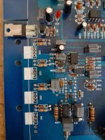
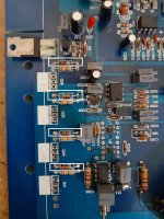
There is a small schematic - D667 + TIP41C, resistor and two diodes supplying the voltage to pin 1 of the IR2011. The diodes have been replaced by a previous repair attempt and i'm not sure they are the right ones.
I did check the bootstrap diode + cap, all fine. The circuit is almost 100% the same as in the datasheet for Infineon-IR2011.
Any reference with the correct voltages for ir2011 would help.
Amp is based on IR2011. No output switching, The Ir2011 is a brand new one from a reputable source.
I do have proper square waves at HIN/LIN but it's like the chip is in shutdown mode or do not have the proper voltages at Vcc,Vb,Vs.
There is a small schematic - D667 + TIP41C, resistor and two diodes supplying the voltage to pin 1 of the IR2011. The diodes have been replaced by a previous repair attempt and i'm not sure they are the right ones.
I did check the bootstrap diode + cap, all fine. The circuit is almost 100% the same as in the datasheet for Infineon-IR2011.
Any reference with the correct voltages for ir2011 would help.
Attachments
First step is to check whether low side gate pulses are ok. Then you should understand the operation of hi-side driver power supply with its charge pump. To supply the hi-side driver, the diodes must be operational and at least one low side power-Mosfet as well, but no hi-side PowerMOSFETs at this time. At this stage the floating supply DC-voltage of the hi-side driver should be apparent, to be measured with a DVM. And hi-side gate pulses as well.
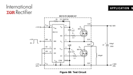
attached picture is for ir2110 which is different than irs/ir2011.The IRS2011 is the same as the IR2011.
Your voltages are not right as they must be measured with pin3 as the ground reference.
Why using pin 3 ? Shouldn't I use the negative rail as reference ?
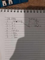
Using negative rail as reference ir2011 and injecting some sinewave thru the rca I get.
1-4.3v
2-49v
3-49.3v
4-49.6v
5-2.5v
6-2.5v
7-0v
8-0v
Pin 1 is too low. It should have about 12v (referenced to the negative rail). Find its regulator.
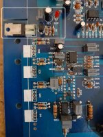
It's the section in white... D667 + TIP41C, resistor and two diodes supplying the voltage to pin 1 of the IR2011, the emitter of the tip41 is directly tied to pin1 of the ir2011. The two diodes have been replaced by a previous repair attempt and i'm not sure they are the right ones, nor i'm 100% sure that Tip41C is the original part as it seems there has been soldering and flux residue.
Attachments
Tip41C
B-8v
C-48v
E-4.3v
D667
B-8v
C-48v
E-8.47v
Both have been tested out of the board on a transistor tester and were fine....
B-8v
C-48v
E-4.3v
D667
B-8v
C-48v
E-8.47v
Both have been tested out of the board on a transistor tester and were fine....
Are you 100% sure that you have the right pin configurations?
Does the diode with the brown band connect between the negative rail and either of the transistor bases?
Does the diode with the brown band connect between the negative rail and either of the transistor bases?
my bad, D667 is:
E-8v
C-48v
B-8.47v
The 4.7kohm resistor above both diodes is getting really really hot.
Does the diode with the brown band connect between the negative rail and either of the transistor bases - yes, it does connect to the base of the D667. The voltage drop across this zener diode is 5.5v. There is also 2v drop from the LED and 0.6v from the other diode which one is actually tied directly to the negative rail.
Are you sure the collector voltage (and the rest of the voltages) are negative with the black probe on the negative rail?

TIP41C is broken!Tip41C
B-8v
C-48v
E-4.3v
I've used a 10v Zener. Now I've 11.8v at the IR2011.
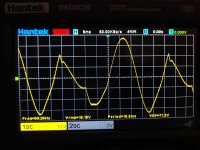
Amp works fine but just for the first few watts. If I load it a speaker or a resistor and increase the gain even a little bit I got this on the output, picture attached.
(I have already pulled out all of the outputs and measure them on the transistor tester, they all read fine and match by parameters.)
The diodes at the low side (in white) have been changed by the previous repair attempt. I've not checked them if they are the same ones used as in the high side, maybe they are the culprit ?
Attachments
Does the voltage at the IC remain at 11.8v when the amp starts to distort?
Does it do this with no load?
Does it do this with no load?
Last edited:
With no load, no issues, only when using speaker or a resistor.
Once it starts distorting the signal, the voltage at the IC bumps to 12.3~12.4v.
Once it starts distorting the signal, the voltage at the IC bumps to 12.3~12.4v.
- Home
- General Interest
- Car Audio
- IR2011 class D issue