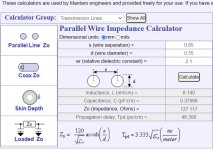
Paralel wire impedance - calculator

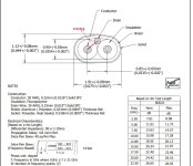
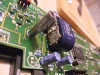
I am experimenting with Usb cables form different brands from cheap to very expessive ones. Because of the reults, I deceided to build own usb cable. Till now i used famous factory branded cable with 90ohms impedance. Before i start to make my new one with bare wire I started with impedance calculation. When i put "Factory" cable dimensions in calculator i don"t come close to 90 ohms. If I think correctly ... impedance between paralel D+and D- wire should be 90ohms and also impedance Between D+ and GND and D- and gnd should be 45-50ohm. So therefore should be drain wire on the picture connected to gnd pin not shelf? So when i made cable drain wire was connected to gnd together with gnd from power supply +5 and GND wire. Then was copper shield connected to metall shelfs on both sides with no conntact to one of 4 pins on connector. Any idea where my thinking was going wrong way. Factory was for sure knowing what they are doing...

Attachments

  • Impedance.jpg
    Impedance.jpg
    140.2 KB · Views: 188
  • impedance calculator.jpg
    impedance calculator.jpg
    84.5 KB · Views: 255

  • Locked
Aggressive Salesman

In the last six weeks, I have been targeted by extremely rude and aggressive solar power salesmen. They really want to put solar panels on my house.

First was at Home Depot. I had hired a helper with a truck and we has a large order to put together. I was buying siding and supplies for my project (almost done). We were very busy and time was a factor. This guy really bugged me and wouldn't take no for answer. He didn't seem to care that he was interfering with my business. When I walked out of the store he was screaming at me.

My doorbell rang a couple weeks later. I couldn't see who was out there (I was alone) and I opened the door. The sales pitch started immediately. "I'm not here to try to sell you something" and thirty seconds later he's trying to sell me solar power. As soon as he said "solar" I slammed the door in his face (he did lie to me just 30 seconds earlier) and he screamed at me through the door for about 30 seconds.

What gives? Is this what they teach salesman now? Do people actually buckle and sign up because some young prick screamed at them? I'm missing something here.

JJ 300B supplier in the UK

I am looking to replace the four JJ 300Bs in my Kevin Kennedy-designed monoblocs. The last time I did this I bought from BTB in Germany, but that was pre-Brexit and I would rather avoid the pantomime of dealing with import duties from the EU.

I am looking for a matched quartet, and would prefer to stay with JJ. Can anyone recommend a good UK supplier who keeps a large enough stock to be able to guarantee four well-matched valves?

Alex

C Audio RA1001 Service

Just done a service on one these old C Audio RA1001 amplifiers. UK made Mosfet outputs. Sounds very good! Plenty of potential to add more MOSFETS and filter caps. Needed the fan oiled, cleaned, a few dry joints, new caps and slight damage to a trace needed repair. Clearly this one has had been repaired in the past. New zobel resistors been installed (oscillation problem perhaps in his history)

It's a shame many of the PA amplifier manufacturers moved away from MOSFETS. HH Electronic, C Audio, BK Electronics, Citronic... All UK made.

20231112_131444.jpg


20231112_123059.jpg


20231112_123103.jpg

Exicon and SML

20231116_112020.jpg

Potential of a short on metal cable stay coming away from board.

20231116_113019.jpg

Trace repair

20231116_113607.jpg

LED very bad dry joint!

How to remove a dustcap

Here in pictures if you ever wondered how to remove a dust cap without damaging a driver.

With this tweak I changed a "bass driver" to a fullrange driver. Got approximately +4 to 5 decibels above 1.5 kHz.

The aluminium voice coil emanates a lot of good high frequencies usually getting lost being buried by a dustcap.

I use further dsp correction together with a current drive amp to lower distortion and get linear response.

Usually I cover both sides of the diaphragm with aluminium foil to get a sandwich cone as DIY "for free"

Attachments

  • IMG_20230318_115006.jpg
    IMG_20230318_115006.jpg
    492.2 KB · Views: 229
  • IMG_20230318_115032.jpg
    IMG_20230318_115032.jpg
    596.8 KB · Views: 213
  • IMG_20230318_115047.jpg
    IMG_20230318_115047.jpg
    294.7 KB · Views: 198
  • IMG_20230318_115135.jpg
    IMG_20230318_115135.jpg
    300.6 KB · Views: 204
  • IMG_20230318_115143.jpg
    IMG_20230318_115143.jpg
    409.5 KB · Views: 226
  • IMG_20230318_115231.jpg
    IMG_20230318_115231.jpg
    404.7 KB · Views: 199
  • IMG_20230318_115401.jpg
    IMG_20230318_115401.jpg
    376.1 KB · Views: 213
  • IMG_20230318_115418.jpg
    IMG_20230318_115418.jpg
    346.8 KB · Views: 200
  • IMG_20230318_115540.jpg
    IMG_20230318_115540.jpg
    382.3 KB · Views: 206
  • Like
Reactions: AllenB

Califoria Audio Lab - Aria (CD player)....problems????

HI, I purchased a used California cdplayer model Aria (with valves), I think it is the MK1 version.
I have some questions.
Inside there are two LEDs, one LED turns on after you hear a clickKK... I assume one or more relays switch , the other LED never turns on. It's normal?

Do you know where I can find documentation regarding this device? User manual, service manual....

Some other questions, of secondary importance:

What is the "CM" function button for? See image with yellow arrow.

What is the "FTS" function button for?...see image. When I push this button the relevant LED starts to flash. If I push the button again the LED goes back off.

I attach some images.

Thank you

Attachments

  • 20231116_192528.jpg
    20231116_192528.jpg
    302.2 KB · Views: 146
  • 20231116_192545.jpg
    20231116_192545.jpg
    457 KB · Views: 130
  • dd.jpg
    dd.jpg
    82.9 KB · Views: 120
  • Screenshot_4.jpg
    Screenshot_4.jpg
    101.4 KB · Views: 136
  • Screenshot_5.jpg
    Screenshot_5.jpg
    73.6 KB · Views: 128
  • EE.jpg
    EE.jpg
    82.7 KB · Views: 128

BoxSim simulation GGNTKT Model M-1 clone with momopol / cardiod bass mode

Sorry for the typo in the title - it sould be monopol / cardioid bass mode
Hi all,
i have read quite closely the ASR thread;
https://audiosciencereview.com/forum/index.php?threads/ggntkt-model-m1.12959/
and have tried to copy the idea and run a simulation with BoxSim ( i am used to it since a decade, i know that VituixCAD is better but i am no good with it)
GGNTKT-Model-1-ASR-Capture.JPGViGGNTKT-Model-1-BoxSim-Gehäuse-Capture.JPGViGGNTKT-Model-1-BoxSim-Frequenzgang-Capture.JPG
I have attached the BPJ file zipped in an archive for those who want to play around with BoxSim, i use the V2.1 DE Version, the file should work also with the V2.0 EN Version
The monopole mode is a piece of cake to simulate, bur i was wondering what have to be done to get the cardioid mode to run that is much better when the speaker need to stand very close at the wall. I have taken the speaker chassis available for BoxSim from Visaton, in VituixCAD the simulation could be done much more closer to the original using the original SB Acoustics 6.5 inch woofer, but it will be difficult to have a decent simulation of the Celestion compression driver mounted in the proprietary 120 X 100 degree directivity pattern waveguide.
As soon as i have understood what have to be done to get the bass cardioid mode to run i would try something similar with some KEF coax chassis that i have - KEF SP1753 4.5 inch as mid high coax that would need three additional woofer or KEF SP1716 8 inch that would need only the rear woofers in addition.

Hope to find some fellows interested in this topic!

- Stefano

Attachments

  • Like
Reactions: burgunder

Cheapfield (Wheatfield HA-2) redux

Hi everyone!

It's been a minute since I've worked on my pmillet Wheatfield HA-2 clone! It had a nasty 60 hz buzz that rendered it unusable, so I sold off the power transformer and stuck it on a shelf to be forgotten about for about 13 or more years. Since then I've moved houses, my kids are grown, and I've wrapped up a masters degree. Having some free time and a pile of non-functioning projects, I turned my attention back to the old creation. It was an easy decision since I had all the parts, and just needed a power transformer and some free time.

So the redux. I've learned a lot more about tube amps and circuits in the last decade and when looking at my build, I decided it needed a completely new layout. I used rather large aluminum plate I had laying around and pulled all the good parts off of the previous attempt. I paid more attention to the filament wiring and moved the rectifier as far from the in/out tubes as possible. Three substantial component changes were made: big Edcor power transformer, a huge 600uf film cap replaced the B+ filter section, and the stepped attenuator was replaced with an Alps RK27. I only needed to buy the Edcor.

Last night I got to do a smoke test, and no hum or buzz! OK. Put on some music, and there were good sounds. OK. So I put on a pair of HD650 headphones and wow, this baby slaps.

Some questionable decisions might be the distance of the high voltage filter sections from the tubes, but nothing seems to be oscillating so that is good. Voltage is still a bit low with the 5U4GB rectifier, right around 250v. I'm not sure this is a problem though so I'm not likely going to sweat it. I'll try it with a 5AR4 at some point. Also I could probably benefit from a lower resistance choke.

I have some oak panels I've salvaged from an old piece of furniture that I'm going to use to make the chassis, so stay tuned for that. I also need to clean up some of the wiring that was done for the smoke test. Hooray!!!

IMG_2663.jpeg

For Sale PA150 LM3886 DIY amplifier in copper hardware, DRV134 and gold plated pcb also supplied

PA150 LM3886 pcb with all components to complete less the audio input capacitor "68€ more shipment"
IC's are new and are not applied on the pcb,like main capacitors,power connectors and SMD output resistors
the other components are already assembled, with genuine components,like on the second picture.
Machined Heatsink with the machined copper hardware and ceramic pads can be supplied the cost is 78€.
DRV134 and gold plated pcb can be supplied if requested cost is 16€
I have also power supply pcb's for who want one model the power supply can be used for powers up to 400watt
and the other for powers up to 800watt, power supply partial assembled as example.
Tracked shipment, shipment to US on request.
Payment by paypal
1679686209702.jpg

1679686330133.jpg

Attachments

  • 1679686209705.jpg
    1679686209705.jpg
    413.1 KB · Views: 202
  • 1679686209693.jpg
    1679686209693.jpg
    313.9 KB · Views: 168
  • 1679686209698.jpg
    1679686209698.jpg
    387.1 KB · Views: 189
  • 1679686330120.jpg
    1679686330120.jpg
    297.7 KB · Views: 190
  • 1679686330123.jpg
    1679686330123.jpg
    388.8 KB · Views: 197
  • 1679686330137.jpg
    1679686330137.jpg
    428.6 KB · Views: 202
  • 1679686403471.jpg
    1679686403471.jpg
    472.3 KB · Views: 205
  • 1679686403465.jpg
    1679686403465.jpg
    503.2 KB · Views: 197
  • 1679687900443.jpg
    1679687900443.jpg
    285.5 KB · Views: 214
  • 1679686403459.jpg
    1679686403459.jpg
    423 KB · Views: 201

Math books?

Hello. Since I started trying to learn about diy audio, my learning has been constantly restrained by my ignorance of math. Many of the texts I try to read through presuppose knowledge that I just don't possess, and inevitably, I get confused. So, I have decided to take a step back for the time being and try to develop some foundational knowledge. I just ordered the book Basic Mathematics by Serge Lang. It seems like it focuses mostly on algebra, although apparently it also gets slightly into trig, and even has some stuff on proofs. Does anyone have any other recommendations for books that I should read so that I may more meaningfully engage with this community? Maybe a book specifically about electronics? Or would such books also presuppose knowledge a layman might not possess? Thank you.

Help me understand? 10kHz square wave thru my SE amp

Greetings friends. Having recently figured out how to hook up an oscilloscope+signal generator to an amplifier, I'd like to analyze my daily listener. So I put the sig gen in the 3k-65k range and put the scope on the 4-ohm resistor across the output terminals. Get a wave that looks like this:

IMG_20231112_162252704_HDR~2.jpg


As you can see, there's major rounding of that leading edge. What gives? Amp has no feedback so there's no phase lead cap to adjust. Here's the schematic:
Login to view embedded media
Anything I should look at?

Thanks!

Effects of aging of LED references in current sources

As per title, I was wondering about the effects, if any, of the aging of the LED references. I have a vintage amp that has bipolar BJT current sources with LED voltage references (see positive and negative rails schematic snippets below). These are your garden variety 5mm cheapo red LEDs. They are not run very hard (3.6mA).

Capture d’écran 2023-11-14 222700.png
Capture d’écran 2023-11-14 223220.png


I live in an imaginary world where licorns thrive and silicon junctions are eternal, but I guess they must have a life expectancy. The amp is currently open on the bench and I note that the LEDs are quite dim - much dimmer than a new red LED passing 3 mA; some have almost an unoticeable glow. Furthermore they are not all equally lit between halves of the bipolar supply on each current source section. Note that the transistors including the power finals and all other diodes don't seem to suffer aging...

Information on these old amps is scarce but once I stumbled upon an article on upgrading a member of the same series and vintage of amps, which has basically the same circuit but with scaled-down components and power (I have an exemplar of this model as well). The author, which apparently had a good deal of experience in restorations and upgrades, wrote that he systematically replaced current source LED references.

So I guess I should too, or was he over-zealous?

crossover restoration - should I use film caps?

so I bought some speakers where the crossover need some fixing.

While in there I saw that the caps used were electrolytics and wants to replaced them with film caps. My issue is the size of the caps used.
  1. 100uF 100V
  2. 22uF 100V
My issue is the 100uF one. that's a HUGE cap.

I'm thinking that maybe this can be installed off-the-PCB using wire to extend the leads? and perhaps using some zipties to keep it in place?

Also, is it worth replacing the cement resistors with something like Mills wirewound?

Thanks a lot of the response!

600v IGBT shortage, replacement for HGTG30N60A4D

It appears that there is quite the shortage in IGBT's at the moment, with wait times as long as 9-12 months!
I've used all my stock up of HGTG30N60A4D 's, which are used in many pro audio amplifier SMPS's. They are designed for high frequency (100khz, 200khz at lower current)

HGTG30N60A4D was made obsolete a few years ago, I currently stock a pair of IXGH48N60C3D1 , these look like they should be a suitable replacement given the switching frequency used of 40kHz in the amplifier I am currently repairing. Would somebody be able to compare these two devices and see if I'm on the right track in terms of these being a suitable replacement?
However, the IXGH48N60C3D1 are also out of stock, so once I use these, i'll have to find another replacement for future repairs.

Can anybody recommend replacement IGBT's for the HGTG30N60A4D? The Replacement must have a build in Free wheel Diode.
I found this one from On Semi that is in stock, FGH75T65SHD-F155 , looks similar in terms on turn off delay times, gate charge and Qrr. It seems there is much more range in the 650v IGBT's than 600v IGBT's.
Is there much of a drawback in using a 650v IGBT in place of a 600v one?

If anybody could help with suggestions that are in stock at Mouser / Digikey / RS Components, It would be much appreciated.

FS Carnhill XFormers for 1173 Projects

I have 16 each of the Carnhill VTB1148 Output transfomer and the VTB9045 Mic Input level transformers for sale.

They are brand new in the box, never been used. Bough them for a project which I have never gotten around to starting.

Asking $40 for the output transformers and $50 for the input transformers and free shipping to lower 48 via USPS.

Attachments

  • IMG-0862.jpg
    IMG-0862.jpg
    485.6 KB · Views: 212
  • IMG-0863.jpg
    IMG-0863.jpg
    411.6 KB · Views: 172
  • IMG-0864.jpg
    IMG-0864.jpg
    423.9 KB · Views: 162
  • IMG-0865.jpg
    IMG-0865.jpg
    377 KB · Views: 163
  • VTB1148.PNG
    VTB1148.PNG
    420.6 KB · Views: 186
  • VTB1148_002.PNG
    VTB1148_002.PNG
    149.5 KB · Views: 251

For Sale LX Mini XO Kit

This is the version of the version of the kit that comes with all of the electronics (aside from the SMPS).

"This LX Mini XO Kit contains the PCB, 16 matched JFETs, 16 matching resistors R13-20, R35-42, and all the other PC board parts mentioned in Nelson's article (Trim potentiometers, resistors and capacitors"

It is in perfect condition and currently sells in the DIY audio store for $100.

$60 includes shipping the United States.

Mark Levinson no29 weird “issue”

Hello! I have a weird “issue” with my no29 power amp. When I set off the power of the amp the led never shut off totally. It is always light a little as you can see in the photo. Although there is no leak in sound when the amp is off. What it can cause that issue?

Attachments

  • IMG_1886.jpeg
    IMG_1886.jpeg
    391 KB · Views: 87
  • IMG_1885.jpeg
    IMG_1885.jpeg
    374.1 KB · Views: 80

Rotel transformers - Any Interest

I have acquired about 400-500 brand new Rotel Transformers. Rotel used to...or maybe still does im not sure...used to make their service centers buy and stock a certain number of products, boards, cables, connectors and...Transformers...which never fail. so over the years these would just pile up. From my previous experience selling transformers, there hasn't been much interest in stuff for solid state gear...BUT. before i send these all off to scrap...would anyone have interest in any?? if it is worth while i can post some. I have transformers from most of the more recent products in the last 10 years. preamps, power amps, toroids, EI core, R-Core potted. etc etc....problem is. I have Rotel part numbers and SOME say what they were for RC-1550, RSX-xxxx, RA-1555, A-12 etc etc but I don't know what the voltages or current ratings are for any of them. a person would have to research them and I do not have the time nor the desire to do so for a $10-$20 item.
OR, I could do a mystery box...$50 and i send you a box of random transformers and you figure it out.
I just HATE scrapping perfectly good parts! and Rotels transformers were REALLY nice! the canned potted Preamp transformers are really really nice units. and i just do not have the space nor the time left in my life to deal with them all LOL
SO....any interest? any takers? I would LOVE to make a one time deal for all of them! I have a ton of other Rotel parts i need to deal with. boards, chassis covers, etc etc
I am in minnesota and I can ship as I have time between family obligations, biz, work etc.

ZC

Protocol to rapidly "burn-in" a DAC?

I would like help to work out a protocol for rapid stress testing and possibly bedding in a 24bit 384kbit R2R SS DAC.

In the rare event a DAC is going to fail I want it failing asap. I also want to test if playing in makes any difference to perceived sound for better or worse. Id appreciate this thread being a protocol thread. If you want to argue or speculate about the actual reality of burn-in please go to https://www.diyaudio.com/community/threads/burn-in.328225/page-9

Please share your ideas on how to maximise rapid burn-in:
  • Is it good to have a power off time to form caps and do expansion-contraction stress testing?
  • Is white noise with high frequencies going to speed up processing?
  • To activate all components is it necessary to play files with full volume range covering all the bit depths eg white noise from -140 to 0dBFS?
  • Will a low resistance dummy load appropriate stress the output stage?
Please critique the approach below:
1. Play for 11 hours on and 1 hour off for a good ten days.
2. Play a special white noise 24/384 file at -140dBFS to -0dBFS, doing 2Hz-96kHz, alternating with a 2Hz-96kHz sweep
3. use a low value resistor as a dummy load on the output, to stress the output stage and get the current flowing.
4. A/B with a known stable DAC before and after. Ideally have two of the same DACs, burn only one in and listen blindfolded and A/B before and after.

Thanks.

Chamfering driver hole

Help,
Just finished building a set of bookshelf boxes and I'm having second thoughts on the chamfer cut I did on the back side of the driver hole.
The baffle is 36mm thick, the driver hole is 150mm in diameter and the 45 degree chamfer goes down about 15mm, so there's about 20mm inside the hole that is not chamfered. Do you think this is enough for the driver to breath or should I remove more wood?
The 2 options that I am thinking about are 1) Use a Dremel tool and remove more wood, 2) lining the inside of the hole wall with weather strip or felt, I've read that this might do the trick and reduce reflections.
BTW, driver is fullrange, if that makes a difference.
Thanks

90 years of tube porn?

I was given a grubby but serviceable copy the 1933 RCA-Cunningham radio tube manual (RC-11) and was quite looking forward to browsing it. And then I looked at the back cover and saw the distinctly phallic arrangement of valve-and-trademarks surmounting the National Recovery Administration logo and motto: "We Do Our Part".

Now I'm nervous about what RCA-Cunningham might have meant by "doing their part" and what I might find between the covers - surely not a centrefold? :yikes:

Attachments

  • RCA-11 front cover.jpg
    RCA-11 front cover.jpg
    775.1 KB · Views: 267
  • RCA-11  back cover.jpg
    RCA-11 back cover.jpg
    711 KB · Views: 196

LT4320 THT rectifier design feedback

I'm trying to design some pcb's for THT LT4320 rectifiers and I've come up with this design. To try to get plenty of current I've made 2 AC and 2 DC planes. It ends up with a good amount of surface area. My thinking is that:
  • The DC planes do overlap, but any capacitance generated between the DC planes is fine, because we already need capacitors here for the LT4320 to work well (as per the spec sheet)
  • there's no overlap on the AC to AC side
  • There is a bit of overlap from DC to AC, is this a problem?

Does anyone have any feedback? Is this a bad idea for some reason? Do I need to do 2oz pcb for this?

1700156852149.png

LTspice .meas

Does anyone know how to calculate the difference of two dB-levels? Something wrong comes out of this.

.meas AC res20 FIND MAG(V(Vout)) AT 20
.meas AC res1k FIND MAG(V(Vout)) AT 850
.meas res2 PARAM MAG(res1k)-MAG(res20)

strg-L: ->

res20: mag(v(vout))=(-3.30797dB,0°) at 20
res1k: mag(v(vout))=(-25.5767dB,0°) at 850
res2: mag(res1k)-mag(res20)=(-4.00405dB,180°) <---- -22dB expected

Using two 48V 3A POE adapters for the PSU of a MOSFET amplifier?

Hi all!

This is a bit of a 'lazy/cheap/mad' idea of mine that on paper looks fine, but I was wondering what the reality was - has anyone tried this?
I've two spare but fettled Maplin MOSFET amps that I want to pop into an old Sony TA-F6B hulk (I was never really comfortable with the PSU or BJT power amp), and I have two options:

Plan A:
Use my existing spare 300VA toroid + a new softstart relay + resistor (ebay £4+) with new capacitors, perhaps twin bridges to separate the MOSFET supply and the amp PCBs...
..
OR Subversive plan D:
Buy two cheap 48V SMPS PSUs, hopefully quiet ones - yes, it's a lottery, but perhaps the POEs will do, and hook together as a bridge. That in theory gives nearly 300W too, and saves all the bridge and cap work and cost, but at the expense of separate rails for the OP transistors. In a way this is sort of more in the spirit of the original...
..
Plan Da:
A variation on this theme is to use a small 48ish Vdc split analogue supply for everything else, perhaps +/-35-40V would do as it's all regulated down to +/- 30V anyway, and the POEs just to power the MOSFETs themselves (the top source and bottom drain).
..

All thoughts welcome - thanks in advance! 🙂

Compression drivers used quietly with minimal or no waveguide?

For very modest output of around 85dB, it has been pointed out to me that some hifi tweeters can be crossed as low as 1khz or so. And this is true; they'll do so even on the manufacturer's FR charts, at 1watt. Though the lower distortion ones (in my area of the world) are quite costly (e.g. scanspeak D3004, though the SB26 looks reasonable for less) and of course they are being used outside the expected range.

So it has me wondering about compression drivers with small 1" throats, yet a much bigger diaphragm. Even some modest ones would do it 'very' easily, with a tiny fraction of a watt and without any need whatsoever for horn loading at a mere 85dB or so. I'm also happy to use DSP/EQ to flatten and smooth their frequency response. However this is for a compact speaker, there is no way that a big <1khz horn or waveguide could be used; I'd be looking at something much smaller - essentially round-overs, just big enough to avoid bad edge diffraction. I accept this doesn't control directivity, but listening near-field I'm mostly interested in the on-axis results (within reason).

Can anyone help me understand how a compression driver used like this would compare with a hifi tweeter?

Just to anticipate: Yes I realise there are AMTs and full-range/mid-tweeters etc. etc. that would cover the <1khz and higher range. But I want to ask the question if, at a low SPL, compression drivers are also a viable and possibly even better option?

Thanks,
Kev

A Fun FAST project for Christmas break.

I'm planning a build over Christmas for a workshop Bluetooth speaker build around the Bru5 amplifier which has dsp. The brief is it's a fun project and not expecting hifi. It's gotta go load so can be heard over the machinery. The two channels I would like to run a FAST arrangement in mono if the software allows this. The full range will likely be the faital pro fe22 that often get mentioned but I'm not sure what subwoofer to go for. I would like it to be sealed due to saw dust. Something that doesn't mind being EQ'ed. Size of the cabinet and driver isn't a concern within reason but it's a budget fun project so not silly money. The fr driver is £20 the amp was £30 so if I could get a sub for £50ish so I've spent £100 that would be great. (Free wood for cabinet)

Campbell and Holtz Travelers plans

I am trying to find a speaker design to build, being capable with my paws but not being a speaker design Guru.

I hear good things and like the look of Curt and Jim's creations, but a number of the designs I like are either just too big for the room they are intended for (Statements / SII), or there are drivers in them that are no longer available.

I like the Finalists which are an older design, but I have recently discovered there is an update to them - the Travelers. From what little I can glean they would be near perfect for my needs. Trouble is the only place they and their plans seem to be available is Meniscus. Or rather was. I hope they enjoy retirement.

I can probably find the drivers and other hardware, even here in the UK / Europe, but without the plans for cabinetry, crossovers, a definitive list of drivers etc I am stopped before I even start.

So does anybody know where I could get the plans for the Travelers?

E8900

Can the 8900 be ordered preasembled without the Alps volume pot (plan to run it directly from IFI IDSD Pro)
If that’s possible, how much will it cost, shipped in the USA, as reviewed “Full Monty”by HA in the July issue of Stereophile (Lundhall+full AN upgrades+anything else that’s on VK mind for betterment of sound and life), with tubes other than GE?

Cheers

Linn Kremlin FM Stereo Tuner

On the desk I have the above mentioned FM tuner from Linn.
There is an oxidated area on the front PCB arround the 3V6 NiCd accu (memory cell) on the front PCB - go to the attachments so as to mpost #7 and #9 under
Linn Kairn repair
But the actually issue is the fact, this device has not been used for about 20-25 years. This means, that the electrolytic capacitors behind the rectifier must be soldered and reformed by a high-impedance resistor - go to
Reforming Electrolytic Capacitors
is there an other methody of this without the need to unsolder the big blue BHC caps ?
Thank you for advices.

Attachments

  • DSCF4371.jpg
    DSCF4371.jpg
    998.9 KB · Views: 528
  • DSCF4372.jpg
    DSCF4372.jpg
    1,004.4 KB · Views: 517
  • DSCF4374.jpg
    DSCF4374.jpg
    1,002.6 KB · Views: 487
  • DSCF4375.jpg
    DSCF4375.jpg
    992.4 KB · Views: 489
  • DSCF4377.jpg
    DSCF4377.jpg
    1,006.6 KB · Views: 504
  • DSCF4380.jpg
    DSCF4380.jpg
    995.5 KB · Views: 348
  • DSCF4385.jpg
    DSCF4385.jpg
    985.5 KB · Views: 331

Sundown SFB-8000D

I had a Sundown SFB-8000D amp come into the shop yesterday that wasn't giving any output. The guy who brought it in said he bought it off some crack head on Facebook marketplace for a good price, but bought it knowing it was broken. Apparently the original owner was cutting out the transistors to the right of the ones pictured whenever one would blow and take the output out. Best I can figure he also cut the legs on the S5 and S6 ic's as well and soldered them back together.

My problem is Sundown decided in the factory to remove the original markings on the IC's and now I can't figure out what the transistor is supposed to be. Looking this forum I managed to find the missing transistors (which are labeled D1 instead of having part numbers) are IRFP90N20D and the driver IC's (which are also burnt up) are Irs20957s.

The transistors in the photo aren't testing faulty I just don't like the idea of taking all the time to source the missing and blown components and leaving these in in their current state.

I appreciate any and all help.

Attachments

  • IMG_20231112_162723700_HDR.jpg
    IMG_20231112_162723700_HDR.jpg
    409.9 KB · Views: 174

Yamaha A-1000 preamp sound quality

Hello 🙂 I am seeking advice with my yamaha a-1000. I am not sure if it is just my piece or it is standard behavior of this amp, but the sound from the stock preamp is really not nice. It has a really flat sound on mid/high frequencies. But the situation is completely different when I put the input signal directly to the main amp. It started to produce a really nice sound, not boring, not liveless, not flat. So I guess that is something not 100% allright with a preamp. I changed 4x caps (highlighted) on the preamp board. Also cleaned the DIRECT switch, MUTE switch and did measurement on other signal switches, all looks good. Both channels have the same ** sound, so I hoped that IC M5219L is not good, so I swapped it for another(from the main board) but unfortunately it didn't help. Voltages on IC are correct.

Input voltage to the preamp board is +21.5V and - 18.9V (should be +-22V). But I guess that this is not problematic because this is also voltage supply for the IC on the main board (main board sounds great, also on DBT when voltages are even lower).

What else should I try ? Change M5219L for something different (opa2604) and hope that will be better ? Throw a preamp (they call it flat amp, yes I agree 😀) in the trash and use just the main amp ? 🙂 Thank you for your ideas 🙂

Attachments

  • preamp.PNG
    preamp.PNG
    591.3 KB · Views: 221

Mu-follower vs two-triode stage in single ended amplifier with 12AX2-6N2P (PoC)

Hello I want to build a new amplifier using ECC83-12AX7-6n2Pev (all equivalent) and one 6L6GC in SE with GNF (no others please, because I have a lot of them).

I never played with mu-follower.

Can you please check if the mu-follower schematic is correct and which values you would suggest (using the above tubes)

Available AT is 320VAC so I think to get 400VCC.


Second question: what about two ECC83 in series and a 6L6GC with GNF? It gives me a much lower THD% (second scheme) and a much bigger input sensitivity: should this sound better?


Thanks

Attachments

  • mufollower.jpg
    mufollower.jpg
    82.2 KB · Views: 149
  • two-serie-triode.jpg
    two-serie-triode.jpg
    88.3 KB · Views: 131

MJ Magazine (formerly Musen to Jikken) - Yearly Index from 1924 - 2009 wanted

This magazine, founded in 1924 by Mr. Mitsugu Tomabeji, is one of the earliest and most influential radio magazines that I know. In the early years it was Radio experimenter's magazine (Musen to Jikken = Radio and Experiments). The early publisher of this magazine was the currently brand ITO and the currently publisher now is Mr. Seibundo Shinkosha.
https://web.archive.org/web/2008101.../english/corporate-profile/history/index.html
In general this magazine is a DIYer magazine and is very technical but is full of great articles on electronics and speaker design, room acoustics, audio history, as well as reviews, news, show reports, etc.

Very great similarity I note to the french magazine 'l Audiophile from 1977 until 1989 - go for table of contents to
http://6bm8.lab.free.fr/Documentations/Revues/Audiophile/index-1977-1988.html
The table of contents (INDEX) I can get about compact disc's:
CD1: 43 editions from 1977 to 1988- Part I:
go to
https://web.archive.org/web/20100518094713/http://nicolas.davidenko.perso.sfr.fr/revue/revues2.htm
for information in detail. Please note, the kind of the magazine is changed from 1989 (now a normal testing magazine like "Stereophile"
CD2: 32 numbers from 1989 to 1995 - Part II

I want to have all articles about solid state pre-amplifier and power amplifier topologies published in this MJ magazine.
Where I can get table of contents about the MJ Magazine for download or as CD-ROM and what about translations in various other languages?

here various URLs:
http://www10.big.or.jp/~dh/sakuma/index.html
https://web.archive.org/web/2008120...ck/Texts/GeschlosseneGesellschaft/2-5-10.html
JSTOR: An Error Occurred Setting Your User Cookie
??¸ ?'75 Stereo Technic ???????? McIntosh/JBL/audio-technica/Jeff Rowland/Accuphase/?/?¾?????
??????/TOP???
Subscription information for "MJ"
http://www.fujisan.co.jp/Product/244
Patent US4079333
http://www.diyaudio.com/forums/swap-meet/129395-mj-audio-technology-magazine.html
http://www.diyaudio.com/forums/everything-else/136060-why-i-buy-mj.html

BTW - you will get very interesting cover images about google by follow japan keyword:
"無線と実験" (english: "Experiments with radio")

Various Siemens styroflex capacitors

I'm offering theese capacitors, they are all NOS siemens, for sale, minus the cabinet, I'm unsure about quantity, but all drawers are like photos, can on request take more photos.
Asking price 150 euros, or trade with a lcr meter, DER.DE5000 or similar quality, fried my own by accident.
EU only.

Attachments

  • 20231007_085718.jpg
    20231007_085718.jpg
    363.6 KB · Views: 173
  • 20231007_085853.jpg
    20231007_085853.jpg
    476 KB · Views: 172
  • 20231007_085845.jpg
    20231007_085845.jpg
    493.4 KB · Views: 183

Small full range closed back vs open back without enclosure effect on audio

Hi,

My bookshelf tweeter was not working fine so i tried replacing it with same specs but instead of 2 inch I replaced it with 2.5 as my cabinet had more room also 2 inch was not available at that time.

What I noticed is my old tweeter had closed back means spider was not visible, were as this tweet has a open back i can see spider.

So will it make any issue like, moreover

woofer is in different compartment there will be not much air pressure only vibration is a issue they might interfere with my tweeter or not i don't know.

If it is bad so I can replace with closed back one or return this 2.5 inch tweeter and try finding closed back tweeter

Thanks in advance

Tannoy Chester T165 crossover

Hi,

I’ve recently bought a pair of Tannoy Chester in really good shape, 2528 drivers in perfect condition. They sound great but there seems to be something wrong with the hi-end of the spectrum. Resonant/sibilant. After looking inside at the crossover and after some research about the n.1004 crossover I have found the attach schematic. Quite different from a lot of Tannoy crossovers.

The 2528 seem to have the same tweeter/diaphragm as the 2558 and a lot of other Tannoy drivers.

My plan is to build a entirely new crossover starting from the crossover of the srm12 that you can see on the second picture. The driver in the srm12 use the same tweeter diaphragm as the 2528. That’s the closest model that I have found the schematic online. The only modification to that schematic would be the use of a normal coil instead of the autoformer.

Anybody with some experience with this? Any recommandation/suggestion would be welcome!

Merci!

Hubert

Attachments

  • 5F5C4D7B-3998-4528-9E54-D5FC9D94BCD3.png
    5F5C4D7B-3998-4528-9E54-D5FC9D94BCD3.png
    559.7 KB · Views: 382
  • A5117ABB-75F7-4CC5-A269-F23215B4E413.gif
    A5117ABB-75F7-4CC5-A269-F23215B4E413.gif
    30.8 KB · Views: 400

Yuichi A-290 CAD files, modifications and BEM simulation results

A few months ago, there were a few threads that rekindled my interest in radial horns and the Yuichi A-290 in particular. I wanted to make a BEM sim of the A-290 to see it’s directivity and if there were any simple modifications that might result in an improvement. I thought it would be a simple task of transferring the values from the document into a CAD drawing. This turned out not to be the case as the values from the drawings did not create a smooth curve for the horizontal sides. I chose to use a conic curve with a visual best fit between the points in Fusion. The radius dimensions to align the flat section with the fin ends and vertical expansion didn’t quite line up and I decided to fudge it to make it work. The dimensions for the fins produced reasonable curves without any intervention. The original file had the sides being quite flat before curving out as this seemed to match with images of completed horns, I had seen.

I was able to make a mesh and get a basic simulation going. There were a few problems with the model but overall, the directivity seemed to be reasonably constant in the horizontal as touted. The Radiation Impedance was very spiky and odd looking and looked to me like it could be from simulation errors. I knew @DonVK had simulated some similar horns with @docali so I got in touch with Don to have a look and see if he could offer some advice on what I was seeing. It turned out that there wasn’t too much wrong and that the Rad Imp was reasonably consistent with other horns of the same type.

This sparked off several different simulations to improve the model and look to improve the horn without making it into something completely different. Don made all the model iterations. Ideas on fin placement and number from Kolbrek and Dunker’s book were tried along with asymmetric, golden ratios and some other variations. The results iteratively got better and in tandem docali’s Radial Fin spreadsheets were reworked by him and simulated by Don looking for improvements. The horn’s resulting from docali’s spreadsheets surpassed the best attempts at improving the A-290. As a result of lessons learned there, I took another look at the A-290 documents and reworked the CAD from scratch. I drew three-point arcs based on defined coordinates from the drawings for the side profiles and used the data taken from the excel spreadsheet calculations (included in the A-290 doc) for the vertical curves. This time the fin ends lined up exactly at the end of the flat section and the overall result was much cleaner. The best result for a horn based off Yuichi’s plans used 6 fins with a spacing of 7.5,15,15,15,7.5 degrees. The outer two channels being half fins between the fin and wall.

It is still not clear to me if there is a definitive way to produce an exact A-290 as Yuichi intended. What you can find in the attached step and Fusion archives is the blueprint to build either of the versions I created with simulated performance of what to expect.

The V1 is a full 3D solid model, the V2 is a surface model that needs further work to turn it into a full 3D solid for production. Results of selected models to follow in further posts.

Greater simulated performance can be had from similar horns and the information may be released in another thread describing that process or via docali’s sphericalhorns.net website, currently those experiments are still ongoing.

Attachments

  • A-290 V1.zip
    A-290 V1.zip
    451.6 KB · Views: 504
  • A-290 V2.zip
    A-290 V2.zip
    553.2 KB · Views: 430
  • A-290 Qtr Mesh.png
    A-290 Qtr Mesh.png
    63.8 KB · Views: 679
  • A290V2 - Surface.png
    A290V2 - Surface.png
    140 KB · Views: 611
  • A290 V1 3D.png
    A290 V1 3D.png
    99.9 KB · Views: 753
  • A290-V2-3 H Polar Norm.jpg
    A290-V2-3 H Polar Norm.jpg
    30.8 KB · Views: 676

For Sale Bones13 Sell Off - 2

Bones13 Sell Off -> SOLD OUT

I have finished my last project - an n channel VFET amp, which shares duties with a SissySIT r3.

Eyes are going, fingers less nimble, and looking to move across country, and won’t have the space that I enjoy now. I am selling many of these for shipping costs (rounding up and down to $10) Charging half as much for the SITs and VFETs to benefit the community. I bought from proven vendors, but have not tested these.

Anyway, I am going to unload a bunch of boards, VFET/SITs, unstarted and a mostly finished kit. All Vets were purchased from Spencer at DIYCircuit. SITs were obtained from Tomoaki Watanabe.

I am aiming to help the DIYAudio community, but I will prioritize requests from the people who have helped me in the past. Not doing a lottery like the initial VFET sets, but if you don’t have many posts, you will go down the list below folks I know for here, or see that are active here.

Finished boards
1 pair F6 boards, with only the MOS chips unmounted. ($50+$10)

Kits - not started
2 x Reflector power supply boards, and parts ($15+$10 / each)

Boards
1 pair P VFET OS2 boards, with pair of 2SJ28 ($75+$10)
1 pair N VFET OS2 boards, with pair of 2SK82 ($75+$10)
1 3-board set of Pequot Daughter boards ($10)
1 3-board set of Bon Homme Richard boards ($10)
3 single TUBA Boards ($10 / each)
5 single H9KPXG-C push button, slow start switch boards ($10 / each)

(3 will have the SMPS and SL22 parts)

Transistors
1 pair 2SK182E SIT ($50+$10)
1 pair THF-51S ($50+$10)
4 2SK180 (looks to have been recovered, sold as set for shipping $10)
1 pair Sony 2SJ28 ($50+$10)
3 pairs Sony 2SK82 ($50+$10 / pair)

VFET + Boards.jpg
  • Like
Reactions: Cindra and dBel84

For Sale Hypex FA122 Plate Amplifiers - $700 for the pair

For sale is a pair of Hypex FA122 plate amplifiers. These have been lightly used and are in excellent condition. I bought these for a powered monitor project but decided to go in a different direction.

These are 2 x 125 watts with digital and analog inputs. Easy to use and program with the Hypex software.

Original packaging, speaker cable, and instruction manual included.

Asking $700 for the pair. I will cover shipping and PayPal fees at my asking price.

Thanks for looking and please let me know if there are any questions.

DaveJ

Attachments

  • FA122, 1.jpg
    FA122, 1.jpg
    936.2 KB · Views: 77
  • FA122, 2.jpg
    FA122, 2.jpg
    841.5 KB · Views: 77
  • Hypex, 3.jpg
    Hypex, 3.jpg
    841.8 KB · Views: 88
  • Hypex, 4.jpg
    Hypex, 4.jpg
    850.2 KB · Views: 87
  • Hypex, 5.jpg
    Hypex, 5.jpg
    788.8 KB · Views: 88

Merlin VSM issue: advice for a newbie

Hi,

I just bought a pair of the "mythic" Merlin VSM.
I'm a newbie and measurements and I would like some advice please.
A good friend and member of this parish gives me his thoughts, and I'm looking for other ones to confirm.

First of all, I'm not a pro in measurements, first time. Measurements have been done using REW+UMIK (calibrated then).
1 m, tweeter AXIS, mike between tweeter/woofer.
In room, no window.

Issue: when I came back home, plugged the speaker I directly felt something wrong in highs. Nice bass, nice medium, too much medium not enough highs.
They have the Esotar tweeter, supposed to be one of the best, so disappointing ;-)

OK enough blabla, find some graphs below, and please don't hesitate to ask me other or teach me how to make it right.
My goal is to understand what is wrong. Tweeter or crossover?
Thanks

So you have both of Merlin (2+3)
I sent a 5000Hz signal to tweeter to check SPL
I compared with my Sonus Faber Electa Amator II using the same boomer.

Attachments

  • Merlin 2.jpg
    Merlin 2.jpg
    68.6 KB · Views: 146
  • Merlin 3 .jpg
    Merlin 3 .jpg
    74 KB · Views: 141
  • 5000.jpg
    5000.jpg
    104.2 KB · Views: 147
  • Merlin vs Sonus.jpg
    Merlin vs Sonus.jpg
    83.8 KB · Views: 152

Pilot 610 project

I have this Pilot FM receiver that I obtained ... somewhere, mant years ago. I want to add music to my basement workout space, so I picked this off the shelf as a candidate.

Pilot610front.jpg


Pilot610back.jpg


Pilot610under.jpg


Surprise to me, it looks entirely virgin. Original cover, original screws, only dusty. Push-pull 6GW8s may have been replaced, but the rest of the tube complement is Tele and Mullard marked "Pilot."

I could go ahead and do the usual gentle ramp-up and testing, but I'd feel more comfortable with a schematic, or Sam's or something. Anybody have a source?

tia Tim

Two interesting documents. Current Drive Amplifiers and How Amplifiers Treat Big Signals

I came across these two papers from John Woodgate and surprisingly can not find any reference to them on the forum... so here they are. The current drive paper will be of interest to many I'm sure.

Attachments

Woofer suggestions needed for 6L PR enclosure

Hello all,

I'm in the process of designing/making some high end-ish speakers. The problem is that I'm kinda designing them backwards as in I have some cool looking vintage cabs that have 6 liter internal volume so I have to pick my drivers according to that. For tweets i have settled on some Morel CAT 408s and for woofers I was looking at Morel ECW 536 but was wondering If some of yall with more experience could perhaps suggest something better for my goal which is for the speakers to go as low as possible and sound good while doing it. Budget is flexible. Thanks.

vintage Nordmende output transformer

Good morning:
I have been going through my collection of salvaged output transformers trying to set up a new project. I came across a few of these transformers and am curious about them.
I did a turns ratio measurement and ended up at ~ 14k and 1.8k based on 8ohm speaker loads. These transformers came from a SE ell80 radio console.

My request is:
Can someone translate the wording on the attached diagram?

Can some help me determine what will be a reasonable tube to chose for these. The reflected load seems a bit high for most of the common tubes I am familiar with.

I suspect they are in the 2-3 watt range so Flea Power seems in order.


1671035604893.png


Thanks for the help

SB Acoustic TL-MTM build (cabinet advice)

Hi, my name is Frane, Croatia.
Im building TL- MTM:

Woofers: SB16pfcr25-8
Tweeter: SB26adc
(5" augerpro waveguide)

Initial idea was to make sealed tower enclosure based on Grundig Sl1000 MTM topology from 1978. To this date best sounding speaker I've listened to - only "flaw" are 4" woofers. It is suited only for smaller rooms. (And yes - I've heard likes of Magico, PMC Fenestria etc)

However I got interested in idea of transmission line because it offers best of ported and sealed enclosure. But I never heard one, nor built one - just know some basics.

I read lot of stuff few last days on MJK site, however his MathCad sheets are not available anymore. So I started playing with Hornresp, analysing available designs. For example example TrixTrix TL and Dappolito's Thor..

What I have found is - when modeled in Hornresp - those enclosures seem to be tuned 10-15hz lower than Fs of the driver.. and that is without the stuffing which brings the tuning even 5-10hz lower.

From available information for a lowish Qts (0.35-0.4) driver tuning should be slightly higher than Fs, yet every available design I try to model seems to be tuned waaay waay lower. Even when using TL calculator on Hornresp (MJK models) with SB16pfc parameters automated tuning is always much lower than fs.

I will most likely design something like trixtrix short folded tl enclosure because it behaves well in sim, unlike Thor with its 2m long line and small offset..

My question would be.
How low should you tune TL and not run into the problems?

Any ideas and suggestions for enclosure are welcome.

filaments: SNR values for AC/DC?

Hey folks, I know that versions of this question have been beat to death so pardon me. I am having trouble finding metric data and wondering if anyone could help me understand.

I have built amps with clean, tight AC heater wiring and not had too much of a problem. I also have some of the Pete Millett DC boards and I've done some basic DC regulators now.

My question is this: in terms of noise / db / however I should be looking at this, what is the actual noise difference between properly twisted AC and properly regulated DC on a tube filament?

Also: I am not concerned with filament life, electron migration, etc etc. I'm specifically looking for information about lowering my noise floor.

Mark Levinson MC Pre-Preamplifier JC-1 (JC1) - how many Versions at whole are there

Until now I know this Versions:
1) JC-1
2) JC-1DC
both made for battery only and for both the schematic I have - go to this threads:
https://www.diyaudio.com/community/...etween-mark-levinsons-jc-1-and-jc-1dc.243267/
www.diyaudio.com/community/threads/mark-levinson-jc-1dc.372134/
https://www.diyaudio.com/community/...rom-mark-levinson-for-jc1-resp-ro-iii.242541/

But in the meantime I have discover further for me unknown versions:
3) JC-1SM (JC1-SM)
4) JC-1DC series two
5) JC-1AC small power supply
6) JC-1AC high current power supply
7) JC-1 with integrated transformer (maybe a clone of one from previous mentioned)

Who have the associated schematics for this versions ?

Attachments

  • JC-1 SM-IV.jpg
    JC-1 SM-IV.jpg
    102.4 KB · Views: 146
  • JC-1 SM-VV.jpg
    JC-1 SM-VV.jpg
    155.5 KB · Views: 155
  • JC-1 SM-V.jpg
    JC-1 SM-V.jpg
    86.2 KB · Views: 156
  • JC-1 SM-III.jpg
    JC-1 SM-III.jpg
    235.4 KB · Views: 144
  • JC-1 SM-II.jpg
    JC-1 SM-II.jpg
    241.5 KB · Views: 161
  • mark-levinson-jc1-dc ser.-two-top-III.jpg
    mark-levinson-jc1-dc ser.-two-top-III.jpg
    116.9 KB · Views: 135
  • mark-levinson-jc1-dc ser.-two-top.jpg
    mark-levinson-jc1-dc ser.-two-top.jpg
    86.6 KB · Views: 144
  • mark-levinson-jc1-dc ser.-two-rear-III.jpg
    mark-levinson-jc1-dc ser.-two-rear-III.jpg
    61.8 KB · Views: 142
  • mark-levinson-jc1-dc ser.-two-open.jpg
    mark-levinson-jc1-dc ser.-two-open.jpg
    139.1 KB · Views: 151
  • mark-levinson-jc1-dc ser.-two-rear.jpeg
    mark-levinson-jc1-dc ser.-two-rear.jpeg
    22.3 KB · Views: 141
  • mark-levinson-jc1-dc ser.-two-top-II.jpeg
    mark-levinson-jc1-dc ser.-two-top-II.jpeg
    30.3 KB · Views: 124
  • mark-levinson-jc1-dc ser.-two top-IV.jpg
    mark-levinson-jc1-dc ser.-two top-IV.jpg
    120.1 KB · Views: 129
  • mark-levinson-jc1-dc ser.-two-rearII.jpg
    mark-levinson-jc1-dc ser.-two-rearII.jpg
    94.5 KB · Views: 160
  • mark-levinson-jc1-dc ser.-two-review.jpg
    mark-levinson-jc1-dc ser.-two-review.jpg
    67 KB · Views: 129
  • mark-levinson-jc1-dc ser.-two-botton.jpg
    mark-levinson-jc1-dc ser.-two-botton.jpg
    103.8 KB · Views: 132
  • JC-1SM top.jpg
    JC-1SM top.jpg
    40.2 KB · Views: 152

For Sale Duelund Interconnects/speaker cable

Needed a new project 😊 so I decided to re-cable my system so
1 pair 16' factory built Duelund interconnects with no plastic RCAs - $235 (less than price of RCAs
2 pair 6' factory built Duelund interconnects with no plastic RCAs $200/pair (less than price of RCAs
2 12' twisted pair speaker cables 12awg - no connectors $ 60
I will cover CONUS shipping

Streaming through Windows 10

I stream Spotify through a W10 computer to several DACs. one of these is an ifi Zen Dac V2 which is capable of handling DSD and I also have a Topping D30 which also takes DSD. I can go into the W10 sound settings and on Playback choose which rate I want to listen to e.g 24bit 192khz or lower or higher.

If I do this with the Zen the LED shows it is receiving a DSD signal due to the colour of the led. Am I being tricked or does W10 upsample the feed from Spotify and if not what is happening?

WAF Tales

My wife is very understanding of this and other hobbies. Periodically she asks "How many oscilloscopes do you have now?". The number always creeps up. She being a molecular biologist takes this in stride as the academy is filled with such nut-cases as myself.

But this story relates to #3 son who was moved from the West Coast to the North Coast (yes, the sun will come out in April). She is somewhat less accepting of our mutual devotion.

In their new house, he arranges the living room furniture (in contravention to the recommendation of the interior decorator) for an ideal listening position in their family room. (The prior design had two couches facing each other with no room for the JBL 300's.) Another silent wifely commandment is that "There shalt not have any false cables lying on the living room floor before me". He goes on a client visit to Canada for two days and finds that the decorator's instructions have been effected.

What is grandpa to do?

Strange dip in low-end response

So I got around to a project I have been wanting to do mainly for fun: build a larger floorstanding speaker.

But not just any floorstanding speaker - I wanted to try a ported design.

I had this so-so Focal woofer laying around from a component car audio set. Not the greatest thing in the world - but half-decent.

The bigger point of this project was: expiriment with WinISD. I have always built sealed enclosures - ALWAYS. I thought.. why not try a vented enclosure with this little driver just for the fun of it?

Basic Driver specs are:

6 inch woofer
4 ohm
FS = 58hz
(I can post all the TS params if needed)

I measured the TS parameters with Dayton DATS (v3). The specs were pretty close to the factory stated details. And YES, this woofer had a LOT of prior break-in.

So... I went through the tutorial for WinISD. Plugged in the TS params for the woofer. Started a new project: Vented. And off I was - playing around with the numbers.

I found that - according to WinISD - I could set the tuning frequency at 36hz and stay within (less than) 3db all the way. I choose a 2.2 sq ft enclosure and was told (by WinISD) that if using a 3 inch port, it would have to be 4.45 inches long. Done and done.

That was my assumption - and what WinISD showed me.

First - the good news: the bass is DEEP. Surprisingly deep. I actually would say it was a great success except for... I noticed certain songs with various bass notes just did not sound right. So I started to measure.... Somewhere between 52hz and 54hz I get a dip. And by dip, I mean - easily 12db (or more) down. Like... you can clearly see the cone is vibrating hard, but almost hear NO SOUND AT ALL. This only happens within this very narrow band. Below 52, it is solid down to 32hz (lower than the WinISD simulation!). And above 54hz, all is normal.

A tiny 2-4hz gap where sound literally goes mute.

My theory is: this has something to do with trying to push the driver too far below the FS? Perhaps I should have tuned this for something higher?

Perhaps some sort of box resonance?

If this IS likely what happened, could someone give me some pointers when tuning a vented enclosure in regards to the tuning freq and the driver FS?

This project was my first time playing around with vented enclosures like this - and was primarily to get my feet wet.

I am certainly impressed with the results for the most part. I just want to be sure I do not repeat the issue that turned up above.

My next project is moving my dual (sealed) Dayton 15 inchers into a proper dual vented setup. Their FS is something like 19 or 20hz. I have WinISD simulation showing that I can tune the enclosure for these at 14hz with a 14 cu ft box. But after the above, I am worried that this may be too low (??).

-Dean

Thule Audio Vintage Integrated Amplifier IA-120 (IA120) Schematic wanted

Today I get a very fine sounded vintage amplifier for service: the IA-120 (see jpg attachement)

It was sold at a time when the German distributor for Thule Audio was still the same company that at the same time sold the loudspeaker brand ETON (LPG, Neu-Ulm). Approximately between 1984 and 1990.

Perhaps one of the members can post a PDF schematic - Thank you very much

Attachments

  • Thule PA350B.jpg
    Thule PA350B.jpg
    29.5 KB · Views: 1,535

Why many amps use a buffer at input stage?

Many amps use a buffer so they can be used in balanced mode to unbalanced to the first stage
The input stage is often not so low impedance so most preamps could drive the amps without these buffers
Why many manufacturers still use buffers often made with cheap op amps to good circuits ?
Is it only a commercial fashion to use XLR inputs which in reality is not a totally balanced amp ?

Thanks

Do crossovers change ohms with multiple speakers wired in parallel?

I've search high and low for answers and mostly just got more confused. I finally decided to just make an account and ask it myself. So... Hello everyone!

Let's say I matched the number value for impedance all around with a 3 way crossover and 3 speakers. So, one 4 ohm woofer, one 4 ohm mid range, and one 4 ohm tweeter all wired to a 4 ohm 3 way crossover. Will that act as 3 speakers wired in parallel and produce a load of 2 ohms on the input for the crossover?

My actual intentions are to wire two 8 ohm woofers in parallel, two 8 ohm mids in parallel, and two 8 ohm tweeters in parallel to a single 3 way crossover. Will that result in a 4 ohm or 1.3 repeating ohm load on the input of the crossover?

I already have the six 8 ohm speakers, I need a crossover and my radio is 4 ohms.

I know I can use everything as is because ohm ratings are a minimum so the 8 ohm speakers won't damage my radio. But, I'm using a car stereo and a pc power supply as my radio so I only have 50 watts per channel that I want to make the best of. The 8 ohm speakers I have are low power/quality and this radio should be plenty for them even if they're all all wired up in parallel.

Any help will be very much appreciated!

Harbinger Class D Amp with Crossover - No Output

DIYaudio Members:

My friend asked me to look at his Harbinger Powered Speaker. It uses a mono Class D amp with the IRS2092S amp module. Currently, there is no output. I am hoping Harbinger will send me a schematic. The output seems to be going to a Second Order Crossover that is on the Power Amp / Power Supply Board. I am looking at generic schematics for the IRS2092S but there seem to be differences.

The Low Speaker output has 40 volts dc on it. So there is an issue. The two Mosfets tested good. The board also uses a TIP41C NPN transistor - also tested good.

The Power Supply is your traditional Transformer, Bridge Rectifier, two caps. The plus and minus 50 volts are working. I am not a Class D expert but it seems rare that this Class D amp is not using a SMPS.

Any ideas on troubleshooting or trying to find a schematic that might be close to this particular unit?

Thanks in advance, Tom
Projects by fanatics, for fanatics
Get answers and advice for everyone wanting to learn the art of audio.
Join the Community
507,483
Members
7,873,699
Messages

Filter

Forum Statistics

Threads
405,557
Messages
7,873,699
Members
507,483
Latest member
kuttisrank