Hi,
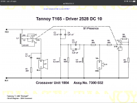
I’ve recently bought a pair of Tannoy Chester in really good shape, 2528 drivers in perfect condition. They sound great but there seems to be something wrong with the hi-end of the spectrum. Resonant/sibilant. After looking inside at the crossover and after some research about the n.1004 crossover I have found the attach schematic. Quite different from a lot of Tannoy crossovers.
The 2528 seem to have the same tweeter/diaphragm as the 2558 and a lot of other Tannoy drivers.
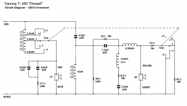
My plan is to build a entirely new crossover starting from the crossover of the srm12 that you can see on the second picture. The driver in the srm12 use the same tweeter diaphragm as the 2528. That’s the closest model that I have found the schematic online. The only modification to that schematic would be the use of a normal coil instead of the autoformer.
Anybody with some experience with this? Any recommandation/suggestion would be welcome!
Merci!
Hubert
I’ve recently bought a pair of Tannoy Chester in really good shape, 2528 drivers in perfect condition. They sound great but there seems to be something wrong with the hi-end of the spectrum. Resonant/sibilant. After looking inside at the crossover and after some research about the n.1004 crossover I have found the attach schematic. Quite different from a lot of Tannoy crossovers.
The 2528 seem to have the same tweeter/diaphragm as the 2558 and a lot of other Tannoy drivers.
My plan is to build a entirely new crossover starting from the crossover of the srm12 that you can see on the second picture. The driver in the srm12 use the same tweeter diaphragm as the 2528. That’s the closest model that I have found the schematic online. The only modification to that schematic would be the use of a normal coil instead of the autoformer.
Anybody with some experience with this? Any recommandation/suggestion would be welcome!
Merci!
Hubert
Attachments
Last edited:
In both cases the variable inductance allows some adjustment between the drivers. The left crossover is fairly conventional, except for what looks like a fourth order filter.
Have you considered simming the difference? (Especially if you can find the values of the autoformer at the tweeter.)
Maybe due to the parallel resistance instead and higher order filter.Why no peak eq just before de tweeter?
Have you considered simming the difference? (Especially if you can find the values of the autoformer at the tweeter.)
Have you considered simming the difference? (Especially if you can find the values of the autoformer at the tweeter.)
By simming do you mean modifying the actual crossover to get it closer to the srm12? Sorry about that, limited english understanding
. I saw somewhere that the green tap on the autoformer on a different model is equivalent to a 2.9mh coil. Not sure if it will work with this driver but I have some part to experiment.
If anything wouldn't it be a better idea to use the SRM10b crossover as a template?
At least they are both 10" drivers.
You just made me realise that the schematic that I have put up on the first post is indeed the srm10b crossover.. So yes, I’m starting from the srm10b crossover.
I’m pretty sure the 2558 used in the srm10b and the 2528 in the Chester use a similar diaphragm and pepper pot throat for the hi end. The question is how far away are the two low end driver and,, what value of inductor should I use to replace the autoformer at the « no gain » position. The green tap if I understand correctly.
The idea of simming would be to understand the differences, see how much there is in this. Then of course you could work out the way to make one like the other if you want, and see if you can relate to the curves and what you hear.
For example, sim each driver, on each crossover, on each extreme of the switch.. so 8 plots.
For example, sim each driver, on each crossover, on each extreme of the switch.. so 8 plots.
Bonjour Hubert,
At the moment I am in the same situation trying to "improve" the filter of Tannoy Dover equipped with 2558.
It's the same chassis as the 2528 with a paper membrane. I took inspiration from different Tannoy filters and tried to keep as much as possible of the components of the Dover filter that I wanted to make identical at the start.
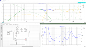
The simulations were carried out with Mr. Bill Waslo's excellent XSim tool after having carried out the SPL and impedance measurements with the other excellent REW tool.
Attached is the layout of the components on an Intertechnik RA 240 PCB and the schematic, which is not very orthodox, but follows the layout of the PCB.
The chokes are Mundorf CFC16, the capacitors are Audyn Cap Plus and the resistors are French 12 W non-inductive TLHP resistors which are also found in La Belle Province at Solen under the name Achromic.
I didn't try to tame the peak at 15 kHz because at my age I can't hear it anymore!
Moreover, when you measure in the axis of the loudspeakers, there is like a boost in the high frequencies.
In my case, the measurements were taken at 3 times the width of the baffle 90 cm (1 yard) and at 1.22 m (4 ft) from the ground.
Plans and measurement files are at your disposal if you wish.
Bernard
At the moment I am in the same situation trying to "improve" the filter of Tannoy Dover equipped with 2558.
It's the same chassis as the 2528 with a paper membrane. I took inspiration from different Tannoy filters and tried to keep as much as possible of the components of the Dover filter that I wanted to make identical at the start.
The simulations were carried out with Mr. Bill Waslo's excellent XSim tool after having carried out the SPL and impedance measurements with the other excellent REW tool.
Attached is the layout of the components on an Intertechnik RA 240 PCB and the schematic, which is not very orthodox, but follows the layout of the PCB.
The chokes are Mundorf CFC16, the capacitors are Audyn Cap Plus and the resistors are French 12 W non-inductive TLHP resistors which are also found in La Belle Province at Solen under the name Achromic.
I didn't try to tame the peak at 15 kHz because at my age I can't hear it anymore!
Moreover, when you measure in the axis of the loudspeakers, there is like a boost in the high frequencies.
In my case, the measurements were taken at 3 times the width of the baffle 90 cm (1 yard) and at 1.22 m (4 ft) from the ground.
Plans and measurement files are at your disposal if you wish.
Bernard
Attachments
Hi Bernard,
Merci beaucoup for your excellent answer. I think I will go forward with that project and start with the same basic crossover than you have used which is I think pretty much the basic Tannoy crossover.
Was the original Dover crossover basically the same? Can’t seem to find a schematic. Have you tweak those the values by ear or are they calculated values ? Have you tried other values for the 2.2mH coil?
Merci!
Hubert
Last edited:
Enclosed is a bit of 40-year-old literature! Waiting for the simulations of the 1004 filter with the curves of the Tannoy 2558. For fun.
Dover is a 30 litre closed cabinet and Chester is a 32 litre bass-reflex cabinet.
The Dover 2558 cone is made of paper and the 2528 cone is made of polyolefin.
The Dover is filtered at 1200 Hz (theoretical) and the Chester at 3500 Hz, which would be very surprising for a 10 inch loudspeaker that has a cone diameter of 182 mm plus 2 x 24 mm suspension in reality!!
See you later.
Attachments
Great I’ve never seen this 1980 review, quite interesting! I have found that there’s two version of the 1004 crossover that have been used with the Chester. The one in my Chester’s that I have posted in my first post and the one in the 1980 review that you can see at the bottom of this post. They are very different. My first guess is that the 1004 in my first post cross over at 3500 and the one in the review cross over at 1500 like you can see in the original spec sheet. I think we can clearly see that someone must have found them to bright if the second one is a later revision. There’s even a 4th coil to filter some hi-end!
Anyway, I’m going to mesure the response my original crossover than start to experiment with a different topology/cross over frequency.
Thank you again!
Anyway, I’m going to mesure the response my original crossover than start to experiment with a different topology/cross over frequency.
Thank you again!
Attachments
Last edited:
I didn't understand the idea of building a different crossover, sorry. Are the crossovers intended for different drivers or for the same? There seems to be a resonance somewhere that needs the CLR network to flatten out. It maybe very specific to a certain driver or a special modified version of it that goes into a specific product only.
The two crossovers have been used in the Chester at some point. You can see some information about that here: tannoy
My goal here is to make them sound as good as they can. I know how a good pair of Tannoys are supposed to sound and I think there is something weird sound wise with my pair of Chester. Im trying to investigate if it’s due to a bad crossover implementation. I find it weird that the crossover is different from what Tannoy normally use on their tweeter. And yes it will surely need something to tame some resonance at the hi end of the spectrum.
My goal here is to make them sound as good as they can. I know how a good pair of Tannoys are supposed to sound and I think there is something weird sound wise with my pair of Chester. Im trying to investigate if it’s due to a bad crossover implementation. I find it weird that the crossover is different from what Tannoy normally use on their tweeter. And yes it will surely need something to tame some resonance at the hi end of the spectrum.
Hello,The two crossovers have been used in the Chester at some point. You can see some information about that here: tannoy
Even though the FRD and ZMA files are those of the 2558, simulations of the two 1004 filters with XSim can be used as a basis for developing a new filter with better components. If you look at the Dover diagram, you will immediately notice that it looks poor. What's more, it looks bad. The 18R and 3R9 of the divider should be reversed and nowhere does it say that the DCR of the choke is 2.2 ohms; this value should be added if you take a recent choke. The purpose of the diy is to learn and tinker.
Fortunately, we have high-performance measurement tools made available to us free of charge by very esteemed people. It helps a lot !
The files are in the attached zip.
Cheers.
Attachments
Wow that’s exactly what I was needing! Thank you for the template, that make it super easy to start experimenting.
I would say that the simulation of my actual crossover look pretty much like what I’m earring : bad peak and valley at the crossover frequency. That’s giving me hope!
Hubert
I would say that the simulation of my actual crossover look pretty much like what I’m earring : bad peak and valley at the crossover frequency. That’s giving me hope!
Hubert
If you are using XSim, don't forget to specify the mod delay in the LF driver setting to align the emissive centres of the horn and the bass: -2.46 in (negative). This is approximately the distance between the HF diaphragm and the LF spider. The difference between both LF and HF IR delays measured with REW is quite the same. So, we can suppose the delay is right. I don't think there are many mechanical differences between the 2528 and the 2558.
Have fun!
Have fun!
I don't understand why they make it so complex, i tried myself from scratch with the measurement done by Glyptoron, and could make it a lot simpler and reasonable flat in about 10 minutes. Off course this is just a sim. I don't know how this will work in real life, but still...
It need notches to flatten the sound, and yes, you loose a bit current with it as they are rather severe notches. But for the rest... Judge yourself.
Dropbox - T165 Ylab-Waxx edit.zip - Simplify your life
It need notches to flatten the sound, and yes, you loose a bit current with it as they are rather severe notches. But for the rest... Judge yourself.
Dropbox - T165 Ylab-Waxx edit.zip - Simplify your life
Attachments
- Home
- Loudspeakers
- Multi-Way
- Tannoy Chester T165 crossover