The obvious "wrong" is the fact that the screen grids of the 6AU6's are not connected at all. The tubes will not conduct enough current to be useful without a positive voltage on G2. You could tie G2 to the plate through a small resistor (about 1K) which will turn them into medium gain triodes. Two triode wired 6AU6's should provide enough gain, but I never tried it. You will also need a resistor from G1 of the 6AQ5 to ground. Use something that's 220K to 470K.Hello,
I am looking to build a small amp with these tubes. Is there anything dramatically wrong with this simple circuit? Or would it be a decent starting point?
You could also copy the pentode circuit from page 2 of the GE data sheet. Pick resistor values from the chart to get the gain you want. You can get enough gain from a single 6AU6 to drive a 6AQ5 well into the distortion zone when cranked.
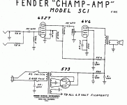
You could also copy the old Fender 5C1 Champ circuit. The early Fender Champ 5C1 used a 6SJ7 driving a 6V6. The 6AU6 is a shrunken 6SJ7 and the 6AQ5 is a shrunken 6V6.
Some of my early guitar amps used a single 6AU6 driving a single 6AQ5 from a small power transformer that used a pair of silicon diodes for the rectifier.
Attachments
Thanks very much for this. This gives me plenty direction and options.
Is the 350k resistor I have connecting pin 7 to ground not the same as connecting it to pin 1? My understanding was that they are connected to each other.You will also need a resistor from G1 of the 6AQ5 to ground. Use something that's 220K to 470K.
Yes, pins 1 and 7 are internally connected inside the tube so the 350 K resistor is fine. I missed that the first time I looked at the schematic. I did a lot of experiments with the 6AQ5 and 6AU6 because I had a lot of them. That was over 20 years ago so I don't remember all the details.
While I had the tube manual open I looked up the 6AU6. It does not internally connect G3 to the cathode so you will need to wire it to the cathode or ground. Every grid in a tube must be connected to something in a tube circuit. Any grid left floating can drift positive or negative depending on how good the vacuum in the tube is, and every tube is different. An unconnected grid can cause random unexpected operation, but usually does nothing or cuts the tube completely off. It can cause fireworks in a slightly gassy tube though.
While I had the tube manual open I looked up the 6AU6. It does not internally connect G3 to the cathode so you will need to wire it to the cathode or ground. Every grid in a tube must be connected to something in a tube circuit. Any grid left floating can drift positive or negative depending on how good the vacuum in the tube is, and every tube is different. An unconnected grid can cause random unexpected operation, but usually does nothing or cuts the tube completely off. It can cause fireworks in a slightly gassy tube though.
you only need one triode stage to drive an EL84 with enuff sensitivity for moderen inputs.
I assume this is meant to be a guitar amp? They usually have at least two gain stages, even the smallest ones.
Instead of connecting the 1K resistor from G2 to plate, connect it from G2 to the B+ supply at point B. You would probably need to mess with the value of the resistor and possibly the cathode resistor as well. Get the amp making sound with both wired as triodes for now, since it's the simplest path to something that makes sound. Once you have sound, you can experiment with component values to get the sound that you want from the amp.How could either of the 6AU6 be wired as Pentodes?
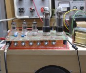
This little amp started out as the remnants of the 4 tube push pull amp I made from the Hundred Buck Amp Challenge which is now a sticky at the top of this forum. There are lots of good ideas scattered throughout that thread. It worked as designed during the thread but got tossed in a box when I had to move everything I owned, twice. Five years later I opened the box and decided to make into an amp that I really wanted. The amp played, but didn't "ROCK." It basically had only one "tone" and sounded rather blah on a guitar that didn't have a lot of output.
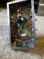
I started by converting an all tube amp into one that incorporated some solid state devices. This stuff was simply tacked onto the existing PC board. I got the basic design running pretty quickly, but that's just the beginning. I wound up with pots in place of several components in the pentode stage. The biggies are that screen grid resistor and the cathode resistor. It took several days of turning the knobs and listening to the amp with 4 different guitars before I found a compromise that I liked.
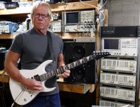
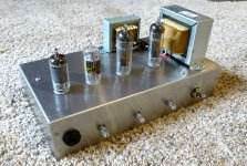
The end result was quite a bit different than the original amp, so once I had a schematic and parts list that I liked, I made a new PC board and chassis for it. I still haven't made a cabinet for it. The original mess is now in a box where dead stuff goes to be robbed for parts. Its remains are sitting upside down on the piece of test equipment to the right of my left ear in the picture with a guitar. This amp was designed for an absolute minimum parts cost, so it used tubes common in the last generation of vacuum tube radios. This allowed for a $12 power transformer. The 18FW6 is a 6AU6 with an 18 volt heater. The 32ET5 is similar to a 6AQ5 with a 32 volt heater.
I said all of this because I still use that amp today. The picture with the guitar was taken over 5 years ago. I'm finally planning some more guitar amps. Making a working guitar amp is not terribly difficult. Making one that you won't grow tired of quickly.....not so easy. The first step is to make something that is safe to use and works. Then the tweaking starts.
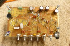
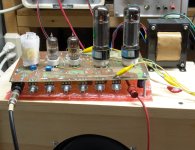
I just looked into the box and found my old test amp. The cathode resistor on the 18FW6 is 620 ohms and the screen resistor is 390 K ohms. The 1K cathode resistor is probably a good place to start, but the screen resistor will need to be in the 200K to 1 meg range and you will probably need a capacitor to ground from the cathode and screen grid. The cathode cap should be 2 to 20 uF rated for at least 25 volts and the screen cap can be a .01 to .1 uF rated for at least your full B+ voltage. Both of these caps affect the tone. My amp uses one pentode stage, the 18FW6 and one triode stage an 18FY6 which is like a 6AV6 with an 18 volt heater.
Attachments
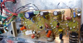
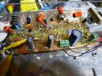
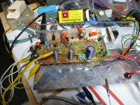
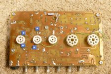
I looked into the "box of broken dreams" (where dead projects go to be mined for parts) to get the resistor values for the pentode stage mentioned in post #14, and I found a relic from 12 years ago (July 2011). I built this as an amp to meet the $100 parts cost requirement of the HBAC. The hacked traces on the PC board sparked up an old memory that I had converted this amp from its original series string heater configuration that used 50JY6 tubes which were $1 each at the time of the challenge to something a bit more traditional.
I dug through some dark corners of my hard drive to find pictures of the 50JY6 version.....
....and the traditional version. Could those be EL34's feeding a real guitar amp OPT???????
Maybe my next guitar amp isn't so far away. My new "can of worms" has been opened, or I should say that an old one is reopened. Now if my brain can figure out what I was thinking 12 years ago.....
Attachments

Thank for the information. I hadnt logged in and was traveling, but will look into all this.Instead of connecting the 1K resistor from G2 to plate, connect it from G2 to the B+ supply at point B. You would probably need to mess with the value of the resistor and possibly the cathode resistor as well. Get the amp making sound with both wired as triodes for now, since it's the simplest path to something that makes sound. Once you have sound, you can experiment with component values to get the sound that you want from the amp.
This little amp started out as the remnants of the 4 tube push pull amp I made from the Hundred Buck Amp Challenge which is now a sticky at the top of this forum. There are lots of good ideas scattered throughout that thread. It worked as designed during the thread but got tossed in a box when I had to move everything I owned, twice. Five years later I opened the box and decided to make into an amp that I really wanted. The amp played, but didn't "ROCK." It basically had only one "tone" and sounded rather blah on a guitar that didn't have a lot of output.
I started by converting an all tube amp into one that incorporated some solid state devices. This stuff was simply tacked onto the existing PC board. I got the basic design running pretty quickly, but that's just the beginning. I wound up with pots in place of several components in the pentode stage. The biggies are that screen grid resistor and the cathode resistor. It took several days of turning the knobs and listening to the amp with 4 different guitars before I found a compromise that I liked.
The end result was quite a bit different than the original amp, so once I had a schematic and parts list that I liked, I made a new PC board and chassis for it. I still haven't made a cabinet for it. The original mess is now in a box where dead stuff goes to be robbed for parts. Its remains are sitting upside down on the piece of test equipment to the right of my left ear in the picture with a guitar. This amp was designed for an absolute minimum parts cost, so it used tubes common in the last generation of vacuum tube radios. This allowed for a $12 power transformer. The 18FW6 is a 6AU6 with an 18 volt heater. The 32ET5 is similar to a 6AQ5 with a 32 volt heater.
I said all of this because I still use that amp today. The picture with the guitar was taken over 5 years ago. I'm finally planning some more guitar amps. Making a working guitar amp is not terribly difficult. Making one that you won't grow tired of quickly.....not so easy. The first step is to make something that is safe to use and works. Then the tweaking starts.
I just looked into the box and found my old test amp. The cathode resistor on the 18FW6 is 620 ohms and the screen resistor is 390 K ohms. The 1K cathode resistor is probably a good place to start, but the screen resistor will need to be in the 200K to 1 meg range and you will probably need a capacitor to ground from the cathode and screen grid. The cathode cap should be 2 to 20 uF rated for at least 25 volts and the screen cap can be a .01 to .1 uF rated for at least your full B+ voltage. Both of these caps affect the tone. My amp uses one pentode stage, the 18FW6 and one triode stage an 18FY6 which is like a 6AV6 with an 18 volt heater.
- Home
- Live Sound
- Instruments and Amps
- 6AU6 6AQ5 6X4 amp