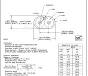
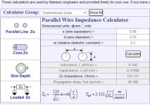
I am experimenting with Usb cables form different brands from cheap to very expessive ones. Because of the reults, I deceided to build own usb cable. Till now i used famous factory branded cable with 90ohms impedance. Before i start to make my new one with bare wire I started with impedance calculation. When i put "Factory" cable dimensions in calculator i don"t come close to 90 ohms. If I think correctly ... impedance between paralel D+and D- wire should be 90ohms and also impedance Between D+ and GND and D- and gnd should be 45-50ohm. So therefore should be drain wire on the picture connected to gnd pin not shelf? So when i made cable drain wire was connected to gnd together with gnd from power supply +5 and GND wire. Then was copper shield connected to metall shelfs on both sides with no conntact to one of 4 pins on connector. Any idea where my thinking was going wrong way. Factory was for sure knowing what they are doing...
Attachments
Some info on USB cable design at:
https://electronics.stackexchange.c...hm-differential-impedance-and-single-ended-45
https://electronics.stackexchange.c...ly-is-the-impedance-of-an-usb-2-0-signal-line
https://www.ti.com/content/dam/vide...491555001.mp4/subassets/usb_layout_basics.pdf
https://www.usb.org/sites/default/files/D2T2-2 - USB4 Cable and System.pdf
Anyway, it appears that calculations can be used to estimate Zo however, it must be measured and the cable design adjusted until is meets spec.
Also, if someone is using nonstandard impedance cable maybe they can get away with it for short lines. For longer lines they might be able to put some electronics in the end connectors that transform the impedance to match that of the actual cable in use.
For longer lines they might be able to put some electronics
I got up to 12m with TI's re-driver.
Alex.
The drainwire is normally part of the shield. It makes contact with the shield over the whole length and its function is also to bridge small gaps in the shield foil when it cracks.
can you explain how results are different between cables? How and what did you measure?I am experimenting with Usb cables form different brands from cheap to very expessive ones. Because of the reults, I deceided to build own usb cable.
Because the shield adds extra capacitance between the wires compared to unshielded twisted pair (UTP). Most UTP in practice will be around 100 to 120 ohms as the geometry isn't super-critical.When i put "Factory" cable dimensions in calculator i don"t come close to 90 ohms.
With STP the extra capacitance will lower that, hence 90 ohms, since adding a shield is a significant change in geometry.
+/-10% variation in Z0 is unlikely to have any practical difference, as the VSWR is not gross for a 10% mismatch.
The best tool to characterize a transmission line is a VNA and S-parameter measurement, but most VNA's are expensive and would require a set of high-spec baluns to interface to differential signal cables...
The cheap way to characterize is change the load resistor to minimize reflection, then that resistor must match the line, but you need fast pulses and fast 'scope to measure this.
Excellent, Very logical. Thank you very much for explanation.
I don"t have possibility to measure eye pattern, so doing diy perfect usb cable is mostly case of luck. Nothing is perfect but close to...
I did not measure any jitter with cables, because i don"t have tool for that.
What nervous me is talking with people and the explain how good base has this usb cable..how transparent it is, how musical it is... has nice colour character...
No ... usb cable should have less jitter and send digital signal as less distorted as possible. So should not add anything and take away - change as less is possible.
I test it so, that i do multiple recording trought usb cable and compare it to original file on ssd ... i don"t care how good music was produced. I just compare with listening test result from ssd or copy on sd or usb (to eliminate copy failure beause of comp signal lines, usb socket connector) VS copy on external ssd or hd trought usb cable.
Its digital, it either works or not. The clock-recovery can be an issue though, that's not a property of the cable though.What nervous me is talking with people and the explain how good base has this usb cable..how transparent it is, how musical it is... has nice colour character...
- Home
- Source & Line
- Digital Line Level
- Paralel wire impedance - calculator

