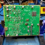
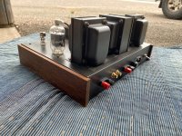
I recently acquired a Kenwood KT-900 analog tuner. This relatively rare model was second in line behind the KT-1000 in 1981. I'd been interested in these even back in my tuner nerd days in the mid-2000s, but had to "make do" with a KT-80 and KT-1100 instead (as well as a number of other non-Kenwood PLL synthesizers). Now I finally bought one and have developed kind of a love-hate relationship with it. It's an attractive-looking tuner that's a pleasure to operate (and works fine again after cleaning the varicap wiper contacts and readjusting the MPX VCO and REC CAL oscillator, both of which were way out, plus the usual tweak of the LO trimmer), but it's also a bit of a mess.
You may know the type.
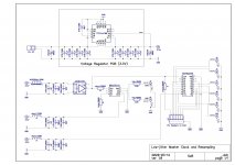
For starters, the schematic is blooper city, and even the actual unit has inherited some bugs, indicating that it may have been a bit of a rush job:
Left and right channels swap places midway through. (Outputs on the actual unit are correct, but I have yet to check which parts go on which channel.)
Frontend power supply choke L2 is being shorted out by the layout but still populated. 🤦♂️ False alarm, looks like you can just barely make out a gap below one of the drawn inductor coils if you look really closely.
Filter switching diodes for WIDE mode are operated at 4.8/10 mA instead of the 3-4 mA they'd normally be using. R9 value should be higher than it is.
There is an extra 100k resistor in series with the 47k feeding the AFC varicap diode for no apparent reason. Maybe they intended to add some extra capacitance but dropped it? (And while the touch sensing duly disables it when tuning, the AFC still strikes me as rather faster than it needs to be, leading to audible low-level LO modulation, same as the KT-80. It can correct nearly 100 kHz in 1-2 seconds.)
B+ routing shown is incomplete. Frontend and IF strip are being supplied via diode D5 in series (not in schematic), dropping their supply from about 13.5 to 12.8 V. (It goes without saying that the regulator suffers from the same load / mains voltage dependency as the KT-80, varying by about 80 mV, and would appreciate the same kind of feedforward mod that I recently developed and deployed in mine, bringing idle/load delta down from 92 mV to 1-2 mV the other way. The KT-1000 and KT-1100 would have this issue as well, it's just less obvious because they don't have a bunch of LED
blinkenlights that can turn on and off.)
Not really a bug, but the unbiased 2.2µ/50V output series caps could probably use some
reforming after over 4 decades. I tried it with the diode test of my multimeter, but that seems to have worked temporarily at best, 2.7 V for a few minutes is just not enough I guess. The unit has a nominal -18 V rail, maybe I'll temporarily borrow that.
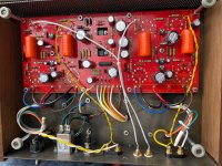
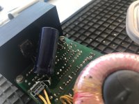
Oh, and electrolytic capacitor C93 was installed touching dropper resistor R181 (100°C in operation), great job assembly person.

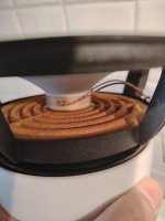
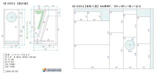
Furthermore, the case construction kinda stinks - tight tolerances and thin sheet metal with little overlap, what could possibly go wrong? (Reassembling it without tuning dragging anywhere is a bit of a challenge.) The paint seems thin and not very robust as well. I liked the KT-80 a whole lot better in that regard, as well as general parts quality. I also tried to find the grub screw for the tuning knob shown in the
explosive diagram, looks like the hole goes all the way down to the shaft. Great, an interference fit.
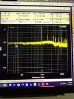
What irks me the most right now is that while sensitivity, selectivity and noise level are good, it generates fairly strong intermod in the frontend with just two pieces of wire on the 300 ohm terminals in my urban environment, while the KT-80 with a very similar frontend - hardly a true miracle of strong-signal handling to begin with - is substantially less impressed under the same conditions. And I'm not even talking cable levels! (Which I can no longer test as analog FM was turned off on there a while back.) I would like to fix that long-term, so here's where I could use some help.
Here are the factors that I think may be contributing to the problem:
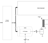
Strike 1 - B+. Where the KT-80 supplies its frontend with 14.9ish V stock and 14.3ish V after my mod, the KT-900's only gets 12.8ish V to begin with. That can't be helping. Not entirely sure why they put the frontend and IF strip behind a diode (if it's needed to avoid reverse discharging, I'll be considering putting in a Schottky instead), and why regulated voltage is only 13.5 V to begin with. (I suppose it's closer to 14 V than 14.9 was, so you could argue that some progress has been made.)
Strike 2 - devilish details.
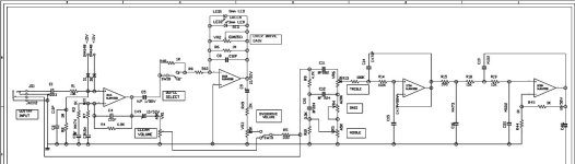
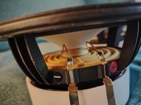
KT-80 frontend (click to enlarge):

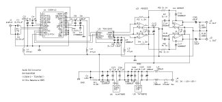
KT-900 frontend:

A lot of things are the same - semiconductors (although an LO buffer is added for frequency counter operation), FM gangs (the varicap just adds the AM plates that had been left out on the KT-80),
Balou the balun (L19-0026-05), resistor values. Coupling caps are a bit different, but who needs a 100p in front of the RF preamp in this frequency range anyway. LC fixed capacitors are bigger in the RF circuits and smaller in the LO, but since actual variable capacitance has to be pretty much the same and so is the range to be tuned, inductances can't be much different and so Q shouldn't be either. (I'll have to compare frontend pictures.)
One thing struck me as peculiar: The KT-80 gets a 1.5p coupling capacitor for the LO, while it's only 0.5p in the KT-900. Now I am not an RF guru, but that has to be negatively affecting LO levels at the mixer, which in turn would be worsening its strong-signal handling capabilities as it always does. My hunch is that the LO buffer Q2 via its 1.5p may have been posed enough of a load that it kept the LO from operating reliably without easing up elsewhere. Also, why does R7 have to be as low as 1.5k? Something smells of "let's bodge it until it works" here.
Great, now how does one fix
that? Do you reckon one could take some hints from the KT-50, a basic little tuner with a frequency counter that used to sit under the KT-80 in Kenwood's lineup around 1980? It uses the same SC114 hybrid but only runs on 8 V, which I guess is what necessitated a bigger value for C7 (one could certainly add a pF or two to the KT-900's 8p as well):

C8 = 1p certainly sounds more promising. Also note R3 = 100k while using the same type for Q2.
Before receiving the unit, I had thought about trying to squeeze in another filter in the wide path, maybe an MA8 or selected MA5 in place of R8 or something, a type with about as much insertion less as needed to get effective terminating impedance (VR1 -> D3 + R14||R15) to about 330 ohms while matching total NARROW insertion loss of an estimated 9 dB:

Diode bias could be fixed while you're in there.
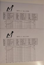
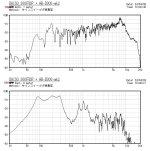
However, selectivity with the two MLs (280 kHz midrange GDT) in WIDE in this European model is actually quite decent, and I don't have to use NARROW with its two additional MJs (150 kHz regular) all that often.
One MA8 would add about 8/5 MLs worth of group delay deviation while being somewhat more selective than one. Mind you, the result would still be more chill than what the KT-80 shipped with for its compromise bandwidth (1x MM (230 kHz GDT) + 2x MS3G (180 kHz selected) of potentially dubious matching). One could also replace the whole shebang with one MP3 (250 kHz GDT) while losing the gain adjustment, but good luck finding GDT filters in this day and age... I think they were discontinued in about 2008.


 This project is a Group Buy. The public group here must agree - in this thread - on what parts will be sold, by whom, and where. Members must abide by those agreements. Any regular sales of the Group Buy PCB, kits or other specific related items outside of diyAudio or this thread will result in the removal of that person from diyAudio.com This is completely at the discretion of the Moderation Team.