

The voltage divider should be more like 10k instead of 100k, and the lower resistor needs a bypass cap. 10 uF or so. Maybe 100 uF to keep vb clean if you use a wall wart for power (they tend to be noisy and have high ripple).
The negative terminal of that bypass cap is now your “clean” ground. Tie all your audio path grounds including in and out grounds to it. Return that to the battery separately from Pin 4’s of all the op amps.
The negative terminal of that bypass cap is now your “clean” ground. Tie all your audio path grounds including in and out grounds to it. Return that to the battery separately from Pin 4’s of all the op amps.
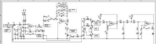
Hello, I am sharing the original symmetrical power supply circuit for you. The part that confuses me is this;
We create a virtual GND with two voltage divider resistors. Do we connect all the grounds in the circuit (except the op amp power input and output signal) to the virtual ground? Can you show this by drawing it on the file I sent to me?
We create a virtual GND with two voltage divider resistors. Do we connect all the grounds in the circuit (except the op amp power input and output signal) to the virtual ground? Can you show this by drawing it on the file I sent to me?
Attachments
Probably nothing wrong with using that virtual ground point as the global audio ground. But my habit is to only use it to establish bias, and run all AC grounds to the bottom end of the bias divider. That way if there is something in addition to op amps that needs ground at zero VDC (like a transistor stage) it’s DC current won’t upset the bias divider.
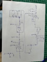
So I should connect all grounds in the circuit (except opamp supply) to the ground and put a coupling capacitor between the opamp sections. Is that right?
I guess the original circuit is intended to work with +- 15v.The original schematic is most certainly designed with as much gain in the input stage as possible to get best signal to noise ratio without overloading it.
If you reduce the voltage to +- 4,5v you have to reduce the gain in the input amplifier in order to not overdrive it.
If you reduce the voltage to +- 4,5v you have to reduce the gain in the input amplifier in order to not overdrive it.
Is it true ? Can you check it please ?
Attachments
What’s posted in #2 is closer to correct. The primary function of the divider is to apply mid point bias, and circuit #9 doesn’t do that but #2 does. The decision to use “vb” as the global AC ground is a secondary concern.
The low pass filters each need their own resistor to the “vb” point, and neither circuit has that.
The low pass filters each need their own resistor to the “vb” point, and neither circuit has that.
Maybe i have somewhat inconveniant views of how to amplify a guitar.
I want a possibility to get a "clean" signal without clipping and for many strange but i think electric guitars get more body in the tone with some second tone distortion. I also want another kind of clipping more like the soft crossover distortion you get in some old tube amplifiers.
And i want at least three high pass filters of around 30 - 40 Hz to block the ultra low frequency that the mic can leave when you pull a string so the speaker cone dont go wandering. That is something that never can pass an output transformer in a tube amplifier but we can fix it without transformer in transistor amplifiers if we design carefully.
I personally is not able to drive that with a single 9 volt battery. I use minimum 25 volts single supply.
Here is an example that sounds good in my ears but maybe to clean. The overdrive circuit is missing.
S2 is midpin of a three way switch. To S3 you get a smooth sound more like some jazz. In the midpoint (no connection) you have some treble lift for usual rock like tone and with S1 you have more treble lift like Spotnicks in the 50:s or maybe Dire Straits. M1.3 is +32v, M1.2 Gnd and M1.1 the output.
To really get clean guitar signal you need a supply voltage over 100 volts. A front end gain of 50 on a 9 volt (or even +/-15V) supply is just to easy to completely overload. Pickups nominally only out out about 50 mV but can peak at a volt or two. You do want overdrive, but NOT ahead of the tone shaping. The very front end is the wrong place to have overdrive/clipping. Compression or large amounts of 2nd harmonic (ie, from a current starved 12AX7) are desirable, but not hard limiting.
Most of the analog section of many digital amps use only a 5 volt circuit for the first amplifier.
To get that to sound clean, you need to attenuate the output of the pickup by a factor of about 100, before feeding into the first op amp. Fortunately, one can get some very low noise op amps these days.
Nah. Just be careful on the gain structure - try to avoid amplifying then attenuating, or vice-versa....To really get clean guitar signal you need a supply voltage over 100 volts.
That's going to add upto 40dB of noise, not recommended. Again, good gain structure is key. Baxandall gain circuit is great here as it can have gain or attenuate without compromizing either noise floor or headroom.To get that to sound clean, you need to attenuate the output of the pickup by a factor of about 100
- Home
- Live Sound
- Instruments and Amps
- split supply to single supply opamp