Hello Community,
i want to build my own audio setup for my desktop PC.
My idea is to have 1 tweeter and 1 midrange woofer on the left and right side,
completing the setup with 1 subwoofer in the center under my PC monitor.
What I am mainly listening to is obviously music, occasional podcasts and movies.
The audiosignal is coming only from the aux output (single ended?) of the PC.
The speakers:
2x Tweeter => https://www.parts-express.com/Dayton-Audio-DC25T-8-1-Titanium-Dome-Tweeter-275-045?quantity=1
2x Mid-range => https://www.parts-express.com/Dayton-Audio-DC160-4-6-1-2-Classic-Woofer-Speaker-295-309?quantity=1
1x Sub => https://www.parts-express.com/Dayton-Audio-SD215A-88-8-DVC-Subwoofer-295-484?quantity=1
The IC's I want to use are the TPA3116 for the tweeter and midrange speakers, the TPA3156 is for the subwoofer.
Configuration of the tweeters 2x15W, midrange 2x50W, subwoofer 1x70W.
Now, my first question is...is this even possible, meaning if this is a reasonable setup, does it make any sense what I am trying to create,
leaving out the fact that there are finished solutions for it?
If this all makes any sense, here is what I managed to do in Kicad 6 until now:
Tweeter schematic:

- I am planning to have a couple of external switches to control the state of the amplifiers,
meaning that I have one switch to mute them all and one switch for the shutdown functionality.
- From what I understand in the datasheet the three IC's need to be synchronized.
I decided to leave it to the 400Khz, for the simple reason because the recommended schematic in the datasheet, already does it this way.
How am I supposed to connect those three IC's together, the datasheet makes the example only with two same IC's. I didn't find any citings stating that there is the possibility of connecting more than two IC's togther, so I guess I won't be able to use a subwoofer in this configuration?
Regarding the master IC, which one should it be? I currently picked the tweeter IC as a master.
- My biggest confusion remains on the plimit voltage divider, which sets the output power limit for the speakers.

This is the formula I found in the datasheet.
For Pout, do I need to take 15W or 30W in the calculation?
Rs is the total series resistance, is this the resistance of the speakers on the output + Rds(on) (120mOhm) + the output filter resistance. What do I do if don't have a filter yet, do I need one?
In theory I have all the values required, except for Vp, so I altered the formula to solve for Vp. I got some results and tried to calculate the voltage divider values with the appropriate formula and came to 13,5KOhm and 10KOhm...obviously I do not feel very confident of the result because of the explained reasons above.
- For the supplyvoltage, can I power it all with 24V?
- When the power output of the amplifier changes, do I need to change any output components too? Like the inductors? Do they remain the same if I want to drive a 15W speaker or 50W speaker?
- The endgoal is to have all the components in THT format, except for the amplifier IC, because I would like to solder it myself. Is this a good idea or should I switch to SMD? Does it change anything on the functionality/quality of the endproduct?
These are the questions for now, I also made the schematic for the midrange and subwoofer, but the questions are the same, just for another usecase. So I am going to leave it out for now.
I am also waiting with the pcb design, since I am not so sure what I started here in the schematic...
With the hope that I have chosen the right section of the forum, I would like to thank in advance those who are willing to go through this project with me.
i want to build my own audio setup for my desktop PC.
My idea is to have 1 tweeter and 1 midrange woofer on the left and right side,
completing the setup with 1 subwoofer in the center under my PC monitor.
What I am mainly listening to is obviously music, occasional podcasts and movies.
The audiosignal is coming only from the aux output (single ended?) of the PC.
The speakers:
2x Tweeter => https://www.parts-express.com/Dayton-Audio-DC25T-8-1-Titanium-Dome-Tweeter-275-045?quantity=1
2x Mid-range => https://www.parts-express.com/Dayton-Audio-DC160-4-6-1-2-Classic-Woofer-Speaker-295-309?quantity=1
1x Sub => https://www.parts-express.com/Dayton-Audio-SD215A-88-8-DVC-Subwoofer-295-484?quantity=1
The IC's I want to use are the TPA3116 for the tweeter and midrange speakers, the TPA3156 is for the subwoofer.
Configuration of the tweeters 2x15W, midrange 2x50W, subwoofer 1x70W.
Now, my first question is...is this even possible, meaning if this is a reasonable setup, does it make any sense what I am trying to create,
leaving out the fact that there are finished solutions for it?
If this all makes any sense, here is what I managed to do in Kicad 6 until now:
Tweeter schematic:
- I am planning to have a couple of external switches to control the state of the amplifiers,
meaning that I have one switch to mute them all and one switch for the shutdown functionality.
- From what I understand in the datasheet the three IC's need to be synchronized.
I decided to leave it to the 400Khz, for the simple reason because the recommended schematic in the datasheet, already does it this way.
How am I supposed to connect those three IC's together, the datasheet makes the example only with two same IC's. I didn't find any citings stating that there is the possibility of connecting more than two IC's togther, so I guess I won't be able to use a subwoofer in this configuration?
Regarding the master IC, which one should it be? I currently picked the tweeter IC as a master.
- My biggest confusion remains on the plimit voltage divider, which sets the output power limit for the speakers.
This is the formula I found in the datasheet.
For Pout, do I need to take 15W or 30W in the calculation?
Rs is the total series resistance, is this the resistance of the speakers on the output + Rds(on) (120mOhm) + the output filter resistance. What do I do if don't have a filter yet, do I need one?
In theory I have all the values required, except for Vp, so I altered the formula to solve for Vp. I got some results and tried to calculate the voltage divider values with the appropriate formula and came to 13,5KOhm and 10KOhm...obviously I do not feel very confident of the result because of the explained reasons above.
- For the supplyvoltage, can I power it all with 24V?
- When the power output of the amplifier changes, do I need to change any output components too? Like the inductors? Do they remain the same if I want to drive a 15W speaker or 50W speaker?
- The endgoal is to have all the components in THT format, except for the amplifier IC, because I would like to solder it myself. Is this a good idea or should I switch to SMD? Does it change anything on the functionality/quality of the endproduct?
These are the questions for now, I also made the schematic for the midrange and subwoofer, but the questions are the same, just for another usecase. So I am going to leave it out for now.
I am also waiting with the pcb design, since I am not so sure what I started here in the schematic...
With the hope that I have chosen the right section of the forum, I would like to thank in advance those who are willing to go through this project with me.
I have zero expertise on the electronics side of things, so can't help you there.
If you use the DC160, as long as the enclosure is a decent size (e.g. the size and format of the BR-1 or Classix II) you might not need a sub. Its bass performance is really good.
If you haven't bought the drivers, I'd be inclined to use the DC160-8 as you could the match it with the DC28F or BC25TG tweeters, so you don't have to worry about developing your own crossover. However, it may not be that difficult to adapt those crossovers for the 4 ohm.
I don't recall seeing any projects with the 'titanium dome' Dayton. Further, its resonant frequency is stated as around 1500 Hz, so you probably wouldn't want to cross it much below 3,000Hz - and my understanding is that the DC160 (either version) won't really sound good crossed at much more than 2,000.
If you're going to use the sub, you won't need a 6.5" woofer - you could go for something like a SB13, DC130 or Peerless 5" mid range.
HTH
Geoff

Hi, firstly the dayton tweeters you mentioned are nice but some say they are a bit bright, in your face, if that isn't something you dislike , get them.
I would use a 4 - 5 inch midrange driver instead of the woofers as mid range . and maybe the 10inch variant of the sub.
I have used the PS95's they dont need a tweeter, ( you can use one tho if you like to , for the very high frequencies. ) Two ps95's with the sub can work well.
or any other 4-5 inch mid range , full range , sb acoustics etc. https://www.parts-express.com/Dayto...ce-Full-Range-Driver-4-Ohm-295-378?quantity=1
https://www.parts-express.com/Dayto...Source-Full-Range-Driver-8-295-349?quantity=1
Or with the woofers you suggest and two tweeters build a two way speakers, a bit bigger in volume you will have enough bass from the DC160's. no sub needed.
I would use a class AB for the tweeters , something like TDA7375 , LM1875. maybe TDA7293, LM3886 for the mids, and only Class D for the sub.
Nothing wrong with TPA3116 tho !.
First of all, thank you for the response.
If I got it right, both of you kind of recommend to just use a tweeter and the midrange woofer. So as @GeoffMillar recommends, I looked up the classix build and i found something here,
classix 2 build:
https://sites.google.com/site/undefinition/bookshelf-speakers/classix-ii
classix 3 build:
https://sites.google.com/site/undefinition/bookshelf-speakers/classix-iii
seems pretty promising for my needs, covering the tweeter and woofer choice.
So one chapter is done, I know what to build now and thank you for that.
Regarding the amplifier choice, the tpa3116 is just what I found with some google search.
I don't have any preferences about which IC to use, looking into the datasheets of the IC's that @xXBrunoXx recommends, it would be much easier to develop something.
Taking this in consideration, I would still be happy if I could use what I managed to do until now (schematic wise), and learn something new in electronics, which is the reason why I started this project.
So before I give it up completely, and start from new, am I in the right place here to ask such a question?
TPA series I woul use only for mobile use, 12→24V batteries.
And... keep it simple and find a complete 2+1 amp+ el.crossover already made and BT equipped - who knows?!
For higher power, 24-36, 48 V and up.
But for home...
And... keep it simple and find a complete 2+1 amp+ el.crossover already made and BT equipped - who knows?!
For higher power, 24-36, 48 V and up.
But for home...
As you're using a sub, a design with the DC130 or SB13 would give you a much nicer mid range. Nothing against the Classix II, which are great speakers for the modest damage - I loved ours - but IMHO the DC130 has nicer mids than its bigger brother. Smaller cabinet, too, for desktop use.
Curt's Tritrix TM https://www.speakerdesignworks.com/tritrix-mt
However, the Vifa used in the Classix II sounds cleaner than the DC28 and doesn't have that sticky dome to attract fluff and grot.
I hadn't seen the Classix III before, thank you for bringing that to my attention. The tweeter is on sale for US$12!
Your choice, of course
Geoff
Last edited:
Okay, definitely choose the classix 3 build with its components.
I am going to build the variation with the front port.
Now I still hang on the fact that I want to build the electronic circuit around it, at least the amplifier...
Where can I get some tips/recommendations on which amplifier IC, I have to choose.
The speakers for the build are the DC160 and the TD25F-4.
As I already mentioned, I am completely open to any help/guidance.
There are many ic's that are good ( if you can find them genuine and not fake ! ). you can get cheap pcb's for LM3886 , TDA7293 , and buy genunie parts from a reputable website. or go discrete , something like the " blameless amp " has good performance and cheap parts, except the transformer and caps.Now I still hang on the fact that I want to build the electronic circuit around it, at least the amplifier...
Where can I get some tips/recommendations on which amplifier IC, I have to choose.
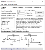
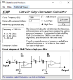
You can also bi-amp the classix 3 build , you won't need crossover anymore ( only impedance equalization circuit maybe )
active crossover https://sound-au.com/project09.htm
calculated the values for 1900hz .
impedance equalization circuit , needs to be calculated but something like this ( first picture ). There is always a good idea to have a cap between the amp and tweeter even if you bi-amp.
Or build them with crossovers and you only need a 2-ch amp.
Many options .
Some more advanced TDA and LM circuits:
TDA7293 improved with j-fet
https://www.diyaudio.com/community/...0-lsk489-composite-feedback-amplifier.413587/
LM3886 modulus-86 by @tomchr
https://www.diyaudio.com/community/...site-amplifier-achieving-0-0004-thd-n.262273/
" Standard " LM3886:
LM3886 pcb : https://neurochrome.com/products/lm3886-done-right
Free design LM3886 https://www.diyaudio.com/community/threads/an-open-source-layout-for-lm3886.321922/
Good guidances for the LM3886 board:
https://neurochrome.com/pages/stability
Chip amps :
https://www.diyaudio.com/community/threads/chip-amp-photo-gallery.79303/page-176#post-7849697
https://www.diyaudio.com/community/forums/chip-amps.40/
LM3886 , TDA7293, LM1875, are the most popular .
Depends what power you require, how high volume you want to drive your speakers.
* Even a genuine TDA7375 ( imo it sounds good ) will make them sound loud. simple to build, only one supply needed ( works with " power bricks " ) a 14.4v at 2 , 2.5A would be enough, cheaper then a transformer, double tap etc.
Attachments

Thank you for the detailed answer.
I think I might stick to the classix 3 design, as it is offered with the crossover, since the last answer I got from you showed me that the amplifier in itself is a much deeper world to explore than I imagined.
Regarding the usage, I don't intend to use it at full power and it doesn't have to be a massive system. I just want to be able to enjoy music and occasionally watch a few videos or movies...just get the most quality out of what 300/400 bucks can give me.
The speakers of the classix 3:
TD25F, 20 Watts, 4Ohm
DC160, 60 Watts, 8Ohm
So I guess I can use a LM1875 for the tweeters and the LM3886 for the DC160.
Does there need to be any "safety margin" for the speaker? If the amplifier is capable of giving 20W, does the speaker need to be rated at 30W?
Regarding the power supply, do I get to design this myself too? Are there finished solutions to it, how are they called?
I come from the electronics world, where a mean-well power supply is doing the required job 99% of the times, is this still the case here?
I guess not, since this type of power supply may bring unwanted noise...i guess
You don't need to turn the amp all the way up, I prefer to have 50W amp and only "use" a few watts, less distortion, you don't overdrive your amp.Does there need to be any "safety margin" for the speaker? If the amplifier is capable of giving 20W, does the speaker need to be rated at 30W?
@fancy_user_123 if you build the passive crossover you won't need two amps, one for the woofers and one for the tweeters. two LM3886;s and you're good.
A simple rectification board with a full bridge rectifier and a few caps would be more than ok.Regarding the power supply, do I get to design this myself too? Are there finished solutions to it, how are they called?
I come from the electronics world, where a mean-well power supply is doing the required job 99% of the times, is this still the case here?
I guess not, since this type of power supply may bring unwanted noise...i guess
"dual rectifier board" , " dual power rectifier filter board" you might find pre made boards, but they are simple you can do it yourself.
Examples here :
https://www.ebay.co.uk/itm/27284671...mkcid=28&google_free_listing_action=view_item
https://www.amazon.de/-/en/Amplifier-Rectifier-Unregulated-Effective-Suppression/dp/B0CHFK9G75
https://it.aliexpress.com/item/4000...909b272483ca6da0e769be8b965&afSmartRedirect=y
https://www.ebay.co.uk/itm/27534053...48215694&google_free_listing_action=view_item
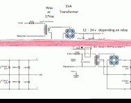
Quick PCB example:
The most expensive parts besides the speakers is the Transformer.
you will need a two winding secoundary, or " double tap transformer" .
LM3886 recommendations are DC ±28V for 4ohm, ±35V for 8ohm .
So +-24 to +-30v would be ok.
Transformer ac voltage multiply by 1.4142 you get the DC voltage after rectification , filtering.
So , 17 - 0 - 17 to 21 - 0 - 21 vac transformer, at least 150VA, 200VA+ would be nice.
Bridge rectifier , 20 - 25A 600V are cheap. ( the square ones with metal casing are/ might be " better " )
Capacitors, lower value more in parallel is better than one big cap, you reduce the ESR ( series resistance ) by doing so, at least 2x 4700uF 50V per rail is ok, more is better, but to much will only cost more and little to no benefits, it can also " stress" the bridge rectifier .( something like + 47.000uf per rail )
Parallel some small 100nF caps ( MKT, Ceramic ) and maybe one 100 - 220uf . On the LM3886 board you'll also need some 470 - 1000uF caps per rail with one smaller value 47 - 100uF and a ceramic ( you can read the article on supply decoupling https://neurochrome.com/pages/supply-decoupling).
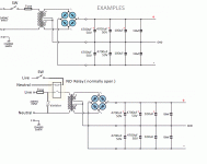
You will need a fuse on the transformer primary. one fuse per rail after the rectification board, can't hurt. but might be a problem if only one blows and depending onthe amplifier you might get DC on the speaker output, anyyway if the chip dies that might happen . A speaker protection board is needed and recommended!.
You can use a relay instead of the switch for the transformer, ( one that works on 220Vac ( so you won't need another small transformer for the relay coil ) and has a few amps, 6 - 10A ).
You can add a varistor in parallel , for high voltage protection, Lightning, etc.
Transformer examples:
https://www.tme.eu/ro/en/details/tst200w_2x17v/toroidal-transformers/indel/tst-200-008/
https://www.tme.eu/ro/en/details/tts200_z230_17-17v/toroidal-transformers/breve-tufvassons/
Using a second transformer for the Relay ( and use a 12 - 24V DC relay ) Will have the benefit that you won't have live voltage on the switch , somewhat safer. a small bridge rectifier and a small capacitor 470 - 1000uF.
- So for the rectification board ( bridge rectifier with capacitors ) you can find " finished solutions " .
The transformer you will need to buy.
A SMPS can also work , but here it depends on it's quality , reliability. I recommend the " old fashioned " transformer. Toroidal are more efficent/ better then I-E core ones.
Schematic drawings were made in a hurry ,.
Feel free to point if I missed something or ..
- Bruno.
Attachments
You can get a smaller VA transformer if it's out of your budget. For what you intend to use , it will be fine. 100VA - 150VARegarding the usage, I don't intend to use it at full power and it doesn't have to be a massive system. I just want to be able to enjoy music and occasionally watch a few videos or movies...just get the most quality out of what 300/400 bucks can give me.
Most commerical amps use undersized transformers.
It would be beneficial to use a bigger transformer, for an 100W amp to have 400VA + transformer or more, but they get expensive. A good quality lower power if not overdriven might be good enough.
My old Toshiba from the 80's has 350W power consumption written on the back and delivers only 45W per channel.
My Pioneer amp 130W per channel has 720W power consumption written on the back, I measured around 400W.
Another amp , Akai made in china , newer amp , uses 7x TDA2030 , 5 ch output. Power consumption is 110W on the back of the amp !. Definitely undersized transformer, it works, it doesn't get hot , but you don't get the full power from the TDA's , at least I measured 20W on the front and center ,and 10W on the other channels.
I have used 150VA transformer , 6800uF per rail for 2x 50W rms amp daily without a problem , overheating , etc. Most people will say it's not enough, undersized,
Higher quality , higher VA Transformer always better , now depends on the budget .
Also you will find that a few watts are more than enough. Especially nearfield , desktop use.
My desktop speakers are two way: Dayton audio ps95 as mid range tweeter and woofer Dayton audio TCP-115 , It's a budget build .
I have listened to them on my Pioneer amp, and also on my TDA7375 amp that has a " power brick " of 14v 2.5A ( 35W ) . And they get plenty loud and sound good . for PC desktop use , movies, games, you won't listen to more than 5W - 10W / channel .
Attachments

So, I went through the answers you gave me.
Since I am from italy, and if I like quality electronic components, I order them from conrad.it/de.
Found components:
Transformer:
https://www.conrad.de/de/p/block-rte-200-2x24-ringkerntransformator-200-va-4-17-a-710747.html.
Output voltage, 2x24V and 200VAC as you recommended
Rectifier:
https://www.conrad.de/de/p/tru-comp...ichter-kbpc-600-v-25-a-einphasig-1581965.html
25A, 600V
IC:
https://www.conrad.de/de/p/texas-in...linear-ic-verstaerker-audio-tube-2994810.html
Regarding the protection board, I am going to look around google on how to size them for the speakers and so on.
I wont list all the smaller components around the amplifier without having a design for now.
Sorry if this may sound a little stupid, but I don't understand what you mean here. Where did you get the multiplication factor? Why do you jump from the recommended 28V of the datasheet, to the 24V and now to 17/21? What does 17 - 0 - 17 mean, the positive and negative output voltage?
From where do I get this value, is this kind of a allrounder or is it mentioned somewhere?
With the switching of the device, I have no doubt to find a solution for it.
And I would like to add that speaker you made looks pretty nice, this is not spraypainted right?
Since I am from italy, and if I like quality electronic components, I order them from conrad.it/de.
Found components:
Transformer:
https://www.conrad.de/de/p/block-rte-200-2x24-ringkerntransformator-200-va-4-17-a-710747.html.
Output voltage, 2x24V and 200VAC as you recommended
Rectifier:
https://www.conrad.de/de/p/tru-comp...ichter-kbpc-600-v-25-a-einphasig-1581965.html
25A, 600V
IC:
https://www.conrad.de/de/p/texas-in...linear-ic-verstaerker-audio-tube-2994810.html
Regarding the protection board, I am going to look around google on how to size them for the speakers and so on.
I wont list all the smaller components around the amplifier without having a design for now.
Sorry if this may sound a little stupid, but I don't understand what you mean here. Where did you get the multiplication factor? Why do you jump from the recommended 28V of the datasheet, to the 24V and now to 17/21? What does 17 - 0 - 17 mean, the positive and negative output voltage?
Transformer ac voltage multiply by 1.4142 you get the DC voltage after rectification , filtering.
So , 17 - 0 - 17 to 21 - 0 - 21 vac transformer, at least 150VA, 200VA+ would be nice
From where do I get this value, is this kind of a allrounder or is it mentioned somewhere?
Bridge rectifier , 20 - 25A 600V
With the switching of the device, I have no doubt to find a solution for it.
And I would like to add that speaker you made looks pretty nice, this is not spraypainted right?
What I wanted to say is : LM3886 recommendations are DC ±28V for 4ohm, ±35V for 8ohm . So , an input voltage ( DC ) of +-24 to +-30v would be ideal. ( +- meaning two rails, two voltages, one with + and one with - respect to ground . )Sorry if this may sound a little stupid, but I don't understand what you mean here. Where did you get the multiplication factor? Why do you jump from the recommended 28V of the datasheet, to the 24V and now to 17/21? What does 17 - 0 - 17 mean, the positive and negative output voltage?
You don't want to be very close to the maximum voltage ( more heat, needs bigger heatsink ).
17 , 21 was the AC voltage not DC. ( that would be around +-24v DC , +-30V DC aprox ) .
By 17 - 0 - 17 I meant two outputs , 17 v to 0 ( Ground ) , because the transformer has two windings, outputs. You need two rails, +V DC and - V DC to Ground .
So, " 17 - 0 - 17 transformer " 2x 17V AC will be 2x 24 V DC .
and 2x 21V AC transformer will be 2x 30 V DC ( approximately ).
Your transformer https://www.conrad.de/de/p/block-rte-200-2x24-ringkerntransformator-200-va-4-17-a-710747.html voltage is 24 v AC,
that will be around 32V .
Sorry maybe the way I explained created confusion, my english needs some more work .
That 1.4142 is the square root of 2 , it's a quick way to calculate AC to DC, approximately.Where did you get the multiplication factor?
Multiplying the AC RMS voltage by 1.4142 (which is the value of 2\sqrt will give you the peak value of the AC voltage. However, this peak value is not the exact DC output after rectification, but it is a good approximation of the maximum potential voltage that would be available from an AC source.
- AC RMS to Peak Voltage:When you multiply the RMS value of an AC voltage by 1.4142 (the square root of 2), you get the peak value of that voltage.
Vpeak=Vrms×1.4142V_{peak} = V_{rms} \times 1.4142Vpeak=Vrms×1.4142
This is the maximum voltage the AC waveform reaches. - Rectified DC Voltage Approximation:After passing through a rectifier, you can approximate the DC voltage as the peak voltage minus the diode drops (for silicon diodes, typically around 0.7V per diode).
However, for a basic estimation of the DC voltage, you could say that multiplying the RMS value by 1.4142 will give you a close approximation of the peak value, and in the absence of significant losses (e.g., in an ideal rectifier), this can be used as a rough estimate of the DC voltage,
Example with 21V RMS AC:
- RMS to Peak (Approximation):
Vpeak=21V×1.4142≈29.7VV_{peak} = 21V \times 1.4142 \approx 29.7VVpeak=21V×1.4142≈29.7V - After Full-Wave Rectification (with Diode Drops):
VDC≈29.7V−1.4V=28.3VV_{DC} \approx 29.7V - 1.4V = 28.3VVDC≈29.7V−1.4V=28.3V
- RMS to Peak (Approximation):
- So, multiplying by 1.4142 gives you the peak voltage, which, after rectification, would lead to a DC voltage close to the calculated value of 28.3V.
The value obtained by multiplying the RMS by 1.4142 is the peak voltage before considering the rectifier and diode losses. For DC, you would need to account for rectification (which reduces the voltage slightly due to diode drops). But as you pointed out, multiplying RMS by 1.4142 gives a good approximation to the peak voltage, and it's often used for rough estimates of the DC voltage after rectification.
- To convert AC (Alternating Current) to DC (Direct Current), several components are used, and the formula or approach depends on the method of conversion. The most common method is through a rectifier circuit (typically using diodes), which converts the AC voltage to DC voltage.
Here's a breakdown of the basic components and formulas involved:
1.
When an AC voltage is rectified (using a full-wave or half-wave rectifier), the DC output voltage depends on the type of rectifier used and the properties of the AC supply.
For a Full-Wave Rectifier:
If you have a sinusoidal AC input with an RMS (Root Mean Square) value of VrmsV_{rms}, the peak AC voltage VpeakV_{peak} is related to the RMS voltage by:
Vpeak=2×VrmsV_{peak} = \sqrt{2} \times V_{rms}
After rectification, the DC output voltage (for an ideal diode, without losses) is approximately:
VDC≈Vpeak−VdiodeV_{DC} \approx V_{peak} - V_{diode}
Where:
- VpeakV_{peak} is the peak value of the AC voltage
- VdiodeV_{diode} is the voltage drop across the diode (usually around 0.7V per diode in silicon diodes, and 0.3V for Schottky diodes)
For a full-wave rectifier with two diodes conducting at any given time, the DC output voltage can be roughly calculated as:
VDC≈Vpeak−2VdiodeV_{DC} \approx V_{peak} - 2V_{diode}
For a Half-Wave Rectifier:
The peak DC voltage is just:
VDC≈Vpeak−VdiodeV_{DC} \approx V_{peak} - V_{diode}
But because only one diode conducts in a half-wave rectifier, the output is a pulsating DC.
2.
After rectification, the output is not a pure DC but a pulsating DC. To smooth this output and get a more stable DC voltage, a filter capacitor is often added.
The voltage across a capacitor after rectification can be approximated (for a simple low-pass filter) as:
VDC_filtered≈Vpeak−rippleV_{DC\filtered} \approx V{peak} - \text{ripple}
Where ripple depends on the load and the capacitor size, and it can be approximated as:
Ripple≈Iloadfrect×C\text{Ripple} \approx \frac{I_{load}}{f_{rect} \times C}
Where:
- IloadI_{load} is the current drawn by the load
- frectf_{rect} is the frequency of the rectified signal (double the AC line frequency for a full-wave rectifier)
- CC is the capacitance value
Summary of Key Formulas:
- Peak AC Voltage:
Vpeak=2×VrmsV_{peak} = \sqrt{2} \times V_{rms} - DC Voltage after Rectification (Ideal):
- For Full-Wave: VDC≈Vpeak−2VdiodeV_{DC} \approx V_{peak} - 2V_{diode}
- For Half-Wave: VDC≈Vpeak−VdiodeV_{DC} \approx V_{peak} - V_{diode}
- Ripple (for smoothing):
Ripple≈Iloadfrect×C\text{Ripple} \approx \frac{I_{load}}{f_{rect} \times C}
- Peak AC Voltage:
This gives you a general understanding of the AC-to-DC conversion process. The actual output voltage will also depend on the quality of the components and losses in the system.
" Bridge rectifier , 20 - 25A 600V "From where do I get this value, is this kind of a allrounder or is it mentioned somewhere?
Any bridge rectifier would work, You need a few amps , so a 6 amp will do , a 10 amp will do.
Oversizing it a bit won't hurt, their price is usually not much .
600V is a standard value for bridge rectifiers, so is 400V.
Get any bridge rectifier you like, find, that has at least 10A and 200V.
Now the difference in price from the 10A bridge rectifier to one that is 20A or 25A is small. So a bigger value might be a good option.
here is another transformer , 300VA , lower voltage. but higher current.
https://www.conrad.de/de/p/sedlbaue...x-230-v-2-x-18-v-ac-300-va-8-33-a-518794.html
with this you will have +- 24.5V . the amp will be cooler with lower voltage . Also, the amp will output less maximum power but more than enough for your need .
https://www.conrad.de/de/p/sedlbaue...x-230-v-2-x-18-v-ac-300-va-8-33-a-518794.html
with this you will have +- 24.5V . the amp will be cooler with lower voltage . Also, the amp will output less maximum power but more than enough for your need .
Last edited:
- Home
- Design & Build
- Electronic Design
- DIY PC/Desktop Setup