
Hi, you need around 0.5mA on the mute so the amp turns on , unmutes.
You need a resistor fron mute to -Vcc , with a cap from mute to gnd. Look in the datasheet.
RM = 54.8k so a 51k res would give around 0.5mA at -30v
27k for RM would work for 1mA at -30v .
So I guess I need to go with a 27K, leaving a little margin when any spikes occur??
in the datasheet graph the max is 10mA , so I guess anything from 0.5mA to 10mA would work .So I guess I need to go with a 27K, leaving a little margin when any spikes occur??
27k would work.
Allright, I managed to pick the components for the amplifier circuit and would be happy if someone would review that first part.
I decided to order from digikey, since conrad did not have multiple components I needed.
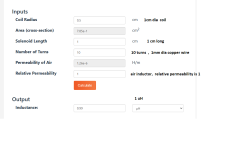
And I am having a hard time finding a 0,7µH Air core coil. Do I need to wind it myself? I never did that...
This is the schematic:

Some details to the components:
@xXBrunoXx I tried to look for the capacitors you mentioned, but I did not find them.
So I picked others from nichicon with the hope they are okay too.
I decided to order from digikey, since conrad did not have multiple components I needed.
And I am having a hard time finding a 0,7µH Air core coil. Do I need to wind it myself? I never did that...
This is the schematic:
Some details to the components:
- R4, R5, R6, R8 metal film resistor
- C8 polypropylene capacitor
- C12 nichicon electrolytic capacitor
- C10 FKP capacitor
- R2 5W
- R3 1W
@xXBrunoXx I tried to look for the capacitors you mentioned, but I did not find them.
So I picked others from nichicon with the hope they are okay too.
Here : https://www.digikey.ro/en/products/...TANCAG4B2aWehA9lANogCsYDAHAyALqEAOALlCBABfEUAI tried to look for the capacitors you mentioned, but I did not find them.
So I picked others from nichicon with the hope they are okay too.
These are bi-polar ( no polarity ) so only for C12 and C8.
You can use this for C8 as well .
https://www.digikey.ro/en/products/detail/nichicon/UES1H100MPM/2597899
@fancy_user_123 Realistically any cap would work, if you want to spend a bit more on Nichicon for better quality parts, won't hurt.
for C12 , frequency is calculated by R8 and C12: fc = 1/(2*pi*R8*C12) , with 470uF and 1K you get = 0.34Hz
47uf for C12 and 1K R8 will give you 3.39Hz .
This is the bass response.
47uf -100uF is enough.
for C12 , frequency is calculated by R8 and C12: fc = 1/(2*pi*R8*C12) , with 470uF and 1K you get = 0.34Hz
47uf for C12 and 1K R8 will give you 3.39Hz .
This is the bass response.
47uf -100uF is enough.
Last edited:
https://www.allaboutcircuits.com/tools/coil-inductance-calculator/And I am having a hard time finding a 0,7µH Air core coil. Do I need to wind it myself? I never did that...
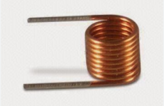
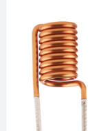
Just wrap a few turns of copper wire on a marker pen or something , and use a bit of glue, super glue after so it maintains shape.
1uH is also good
Attachments
Perfect, thank you for the tips.
I am definitely going to choose the capacitors again.
When I am winding the coil, does the wire need to be anything special, or can I just pick any random one (with the right diameter) from my home depot store?
Next step is the schematic layout, how many gnd layers do I need? One for the audio signal and one for the power input right?
In the end it is a 3 layer PCB, 1 top layer and 2 bottom layers?
enameled wire, copper wire with a varnish , laque coat.
1mm in diameter not section.
"
In Italian, "magnet wire" or "enameled wire" is typically referred to as:
Filo magnetico (magnet wire)
Filo smaltato (enameled wire)
Both terms are used depending on the context, but "filo smaltato" is the most common term when referring to the copper or aluminum wire coated with an insulating layer of enamel, used in winding coils for transformers, motors, and inductors. "
I wouldn't bother with a separate gnd for signal , if not done right it can do more bad than good.
A 2 layer pcb, on the bottom the traces for the all components, the lm3886, and on the top the ground plane where you connect everything that needs to be connected to gnd .
Don't solder the LM3886 on the both layers , it will be a pain , the gnd pin and others make them on the bottom and connect them with " via " to the top copper ground plane.
You can get it with one layer as well, here is what I did so far .
Note that the traces must be on the bottom , flipped. This is the view from top. Mute circuit is missing as well . This is an example, i haven't finished it.
I plan to use 90degree metal brackets to mount the pcb on the heatsink . So the tension is not on the LM's legs.


Thank you again, very kind of you to translate everything!
To be honest, I am pretty happy that this can be solved with a 2 layer PCB, as you mentioned it is a pretty delicate story.
Now that I see an example layout from you, I realized the traces have to be pretty big...
If I remember correctly Kicad has an internal calculator for it and definitely going to copy the brackets too.
I hope I get some time this weekend to start the layout...
A question again about the capacitor that controls the bass response.
I got this value so low because the guide I am following states:
"The cutoff frequency of this filter should be 3 to 5 times lower than the Fc of the Cin\ Rin high pass filter at the input. If the Fc of this filter is higher than the input filter, the amplifier will pass low frequencies to the feedback loop that it can’t handle"
So I guess I need to adapt the input capacitor too?
I have those (93db) - 4R to 6R + 20R (padding). To match those 87-88db mid /sub. DC25 is NOT harsh or bright , just way more efficient !
In fact the DC25 is as smooth as the silk or aluminum dome - if you pad it.
I also have the DS215-8 , it has a much more massive magnet than the SD. SD uses the same VC/spider , but has a wimpy magnet(motor).
OS
That would probably mean that if you input a low freq , like input 5hz and R8 C12 will have a much higher freq , it won't play your 5hz, or very low in volume.A question again about the capacitor that controls the bass response.
I got this value so low because the guide I am following states:
"The cutoff frequency of this filter should be 3 to 5 times lower than the Fc of the Cin\ Rin high pass filter at the input. If the Fc of this filter is higher than the input filter, the amplifier will pass low frequencies to the feedback loop that it can’t handle"
So I guess I need to adapt the input capacitor too?
The input cap with the resistor to ground ( C8 R5 in your schematic ) form a high pass filter, 4.7uF and 20K = 1.7hz
R8 C12 form the low pole, for frequency response to say so. if it's set to 20hz, logically it won't play anything lower than that.
with 470uF and 1K you get = 0.34Hz , it is 5 times lower than your input 1.7hz.
220uF and 1k is 0.7Hz , still good.
I did not hear about the " The cutoff frequency of this filter should be 3 to 5 times lower than the Fc of the Cin " .
Usually set the R8 C12 to 1 , 2hz will reproduce a 10-20hz without a problem.
And you don't need such a low frequency to be reproduced.
I have those (93db) - 4R to 6R + 20R (padding). To match those 87-88db mid /sub. DC25 is NOT harsh or bright , just way more efficient !
In fact the DC25 is as smooth as the silk or aluminum dome - if you pad it.
I also have the DS215-8 , it has a much more massive magnet than the SD. SD uses the same VC/spider , but has a wimpy magnet(motor).
OS
Thank you, good to know. But I think I am going to stick to the classix build.
So I guess 220µF is the final cap value I have to use right?220uF and 1k is 0.7Hz , still good.
You can try different values if you like. See if bass is affected, or you have different results.So I guess 220µF is the final cap value I have to use right?
Sadly, I did not manage to start the PCB layout, but I ordered the components for the amplifier PCB anyways.
After the order was placed, I realized that I ordered every component with a 50V voltage rating, except for C12, I somehow have that capacitor at 35V.
Is this a problem now?...the capacitor is "only" on the VIN- pin, the aux signal is not going to reach 35V, right?
And now I would like to order the rest of the components, meaning:
Bridge rectifier:
https://www.conrad.de/de/p/tru-comp...ichter-kbpc-600-v-25-a-einphasig-1581965.html
Heat sink:
https://www.conrad.de/de/p/fischer-...-5-k-w-l-x-b-x-h-100-x-88-x-35-mm-187739.html
Transformer:
Here I have two options, either 24V or 18V.
I would kindly ask what the difference is, if the VA rating remains the same at 300VA, but the voltage output changes.
18V
https://www.conrad.de/de/p/sedlbaue...x-230-v-2-x-18-v-ac-300-va-8-33-a-518794.html
24V
https://www.conrad.it/it/p/block-rte-300-2x24-trasformatore-toroidale-300-va-6-25-a-710215.html
Rectifier Board:
I changed opinion and now decide that it may be better to buy a finished option, just can't beat those prices.
What I found, since the option given by @xXBrunoXx is not available on amazon anymore.
1)
https://www.amazon.it/Fafeicy-Raddr...da+doppio+raddrizzatore+lm3886,aps,152&sr=8-4
2)
https://www.amazon.it/alimentazione...da+doppio+raddrizzatore+lm3886,aps,152&sr=8-2
Protection Board:
@xXBrunoXx, do you have any recommendation for that?
Except for the speaker components, am I still missing something?
- Home
- Design & Build
- Electronic Design
- DIY PC/Desktop Setup