One thing I forgot, you will need also a heatsink.
https://www.conrad.de/de/p/fischer-...2-k-w-l-x-b-x-h-200-x-100-x-25-mm-188026.html
https://www.conrad.de/de/p/fischer-...5-k-w-l-x-b-x-h-200-x-150-x-25-mm-188034.html
https://www.conrad.de/de/p/kuehlkoerper-aluminium-natur-0-07k-w-200x101-6x32mm-883674545.html
Something like this.
And for the case ? what you have in mind ?.
Thank you !. Actually I painted them with paint roller, use sandpaper 100 - 180 grit, then I wet sanded with 240 - 360 - 500 - 1000 - 2000 -3000 sand paper, and Polished with polish compound . Was my first time doing it, not perfect but I liked the results. it is time consuming tho.And I would like to add that speaker you made looks pretty nice, this is not spraypainted right?
The last couple answers you gave cleared up the confusion a lot.
I started the schematic and am kind of studying the datasheet accordingly.
Since I have to build a whole new desk, I wanted to build it in the desk somehow, maybe even have some transparent sections under the speakers, so that you can see the amplifier and all the other circuits.
Is there anything I need to know about the case, is it better if I build it out of metal?
Regarding the heatsink, the datasheet states this formula:
θSA = [(TJmax − TAmb) − PDMAX (θJC + θCS)]/PDMAX
So I went through the calculations, in a little hurry, and got a value of 0,2746K/W, rounded up to 0,3K/W.
The heatsinks that cover the exact value are a little pricey, is it risky if I take one that you suggested at 0,7K/W?
Am I supposed to match the exact value?
Ah, I see, I had kind of the same idea in mind regarding the speaker design. I really like the finish, and the quality effect they give that way.
Thank you !. Actually I painted them with paint roller, use sandpaper 100 - 180 grit, then I wet sanded with 240 - 360 - 500 - 1000 - 2000 -3000 sand paper, and Polished with polish compound . Was my first time doing it, not perfect but I liked the results. it is time consuming tho.
@fancy_user_123 I am currently building an amp as well, with the LM3886 , I can test it with some small heatsinks and share the results. Also I can send you the PCB I'm making if you want. about the PCB , do you do it yourself , make the PCB design and sent it to a PCB manufacturer ? or you buy one already made?.
Nothing wrong to make it a wood case, They did that in the 70's , 80's .Is there anything I need to know about the case, is it better if I build it out of metal?
Normally metal case will help with RF and EMI , but boards on the test bench ( table ) without any enclosure , work well without trouble. I did build electronics in wooden enclosures before without a trouble.
You can use some non flamable material between the transformer , boards and the wood . stand offs for the boards so it wont touch them.
I also have DC protection for speakers , I need to asamble them and test them . I can share them after that .
Re your question about matching the amplifier output to the speaker power rating.
The amplifier power can be considerably higher than the speaker rating. But you have to be careful. I had this situation and built an indicator which lit up when the RMS power to the speaker was 70% (-3 dB) of the rated output power. It served me well.
Later I built full LED VU meters (LM3915) which are fully excited at 70%. But that is more because I also need to monitor intermediate loudness levels. To avoid harassing my wife.
One very important remark. You can apply the power to a level of the rated power handling to a woofer. But for tweeters the power rating is always the rating for a combined system with an appropriate crossover filter. So a tweeter which is specified for 50 Watts can do so only in a system with a passive filter at a specified cut-off frequency. You cannot apply 25 Watts at 3 kHz to a tweeter!
No manufacturer ever specifies what the actual power rating is for a tweeter. I have been building active systems for 40 years and tried to discover this, but no success. You can only guess what the spectral density of your signal is at high frequencies. There are rules of thumb like 100:60:20 for Lo: MId:Hi. But it depends on crossover. That also leads to the conclusion that it does not make sense to match the output of the high amplifier to the tweeter. If you have proper crossover frequencies, and a 50W woofer and a so called 50W tweeter you are fine if you do not surpass the power to the woofer.
@xXBrunoXx
I would be happy to hear the results about the heatsinks and the protection boards.
Yes, I plan to design it myself, I want to create the schematic and pcb layout, and then send it to jlcpcb...but I want to order the components on conrad/reichelt/rs-components/digikey where I know I can get quality parts, and solder them on myself.
Good point on the non-flammable material, wouldn't have considered it.
@jlinkels
The output power limitation is a point I wanted to talk about again.
The indicator you mentioned, how would I proceed on doing this for the LM3886 circuit.
Do you have any resources where I can read about it?
From what I understand the VU meter is doing the same job, right?
I plan to build the classix 3 speakers.
https://sites.google.com/site/undefinition/bookshelf-speakers/classix-iii
They come with 25W tweeters and 60w woofers, the crossover is already designed and tested by the guy writing the post.
I guess this is fine right?
General question for my understanding.
The guide tells to use the 4Ohm tweeter and the 8Ohm woofer, how is this going to work with the amplifier and the matching impedances it is capable to handle?
Like I explained before, the rating for the tweeter is when the tweeter is part of a system with the appropriate crossover. So this would be a system rating of 25W.
However the designer of this cross-over you are referring to uses a 4 ohm tweeter and halves the power to the tweeter. Which is correct. With this the system rating would be 50 Watts again.
I attach the schematics of the VU meter I built, including the precision rectifiers you would need. In my case I took the voltage at the input of the final amp. The final amp having a fixed gain of 30 dB or 31x.
The dimensioning for mid/high is correct for 50 Watts if your ampliefier has a gain of 30 dB. Most do. If you take the voltage off the speaker terminals you have to build a 30 dB voltage divider.
For the sub you might have to adapt the values according to your sub rating. If you use one.
Adjustment for 50 Watts: The second red LED should turn on at 70% of 50 Watts = 35 Watts. This would be:
U = sqrt (P x R) = 16V RMS. Use a dummy load instead of the speaker when adjusting this. Neither the speaker nor you ears like a continuous signal of this power. Use 400Hz or 1 KHz while adjusting.
If you want to use a single LED for indicating the 35W level, you'd have to build a comparator which triggers when the voltage at the speaker is 16V RMS. To give you an idea, the reference voltage of the VU meter is 6V. So a comparator should trigger at about 4.2V. Once you have that you can adjust the rectifier gain. The schematic I used at the time is not ready for publication so I cannot post it.
Attachments

Or you could install a potentiometer inside the amp , and set it so it will output as much as you like .
Or just don't turn it up that high to begin with.
Tho , that tweeter with a 2nd order high pass filter , also the L pad will be fine even on 100w from the amp.
My Tweeters in my tower speakers only have a 2nd order high pass ( higher frequency at 3000khz , but ) they don't get hot, die, at even 130W on the speaker .
@jlinkels
If the VU meter requires some adjusting with a signal generator, I don't have any possibility other than to use the single LED, since I do not posses a signal generator.
Do you have any comparator suggestions?
What I planned to do from the beginning was to control the volume from the PC, so I guess I wont need a potentiometer.
Since I am going to start the schematic, would it be better to put both amplifiers for the speakers on one board, or split them so that I have one board per speaker?
Both the VU meter and the comparator need adjustment. You want to adjust the level when the relevant LED lights. You might adjust the playback volume in your PC, but you need to adjust the trigger level with a potentiometer.
There must be a ton of applications which include a signal generator for your PC. PulseEffects on Linux is one. Maybe it is available for Windows as well. Be aware that if you olny own a digital meter it might not measure other frequencies than 50/60 Hz accurately.
And maybe you should not worry about overloading your speakers at all. If these boxes are at close distance in not too large a room you become deaf before you reach a level high enough to blow these speakers. Really. It is just nice to have. I had reasons why I built those indicators. These might not be valid for most other users. The cost of one Dayton speaker is probably less than what you would spend on implementing the indicator circuit. One you burned one speaker, start reconsidering adding power indicators.
I don't mean to say Dayton speakers are bad. I use a DC160 as a subwoofer in a different application and I am very satisfied.
Okay, so in the end I wont build a VU meter, and do as @xXBrunoXx suggested...sorry.
My idea to not implement a poti and just regulate the volume from the PC, is this something reasonable?
My idea to not implement a poti and just regulate the volume from the PC, is this something reasonable?
No problem with that. Just don't plug , unplug the amp while its powered on. Do that before you turn it on. (to avoid buzz and a thump in your speakers).My idea to not implement a poti and just regulate the volume from the PC, is this something reasonable?
Also don't forget to add the input RF , EMI filter, and output zobel.
Attachments
@xXBrunoXx That is a nice circuit. I think it is a perfect match for a 50W speaker system.
You set a gain of 21 (26 dB). This is also in the TI application note. Usually amplifiers driven from a PC have a gain of 30 dB. And I find that even on the low side. The gain of the PC + final amp is often not high enough to get sufficient audio volume. Especially with some Youtube videos which recording level is simply low. And I have to add an additional pre amp of 10-20 dB. Is this low gain satisfactory for you? Just asking.
Now I also see that Ali Express has some very nicely priced (stereo) boards built around the LM3886. Those are prices I am totally unable to design and have PCB made, buy all the components and the heatsink. The heatsink alone is usually half of the total price. And since nowadays mainly complete assortments of active components are offered (of which 80% I'll never use, talk about waste!) I would not able to build this board myself for a price even close to that. Even if the board contains some fake components they are easy and cheap to replace.
I was planning to buy some TDA7293/94 boards as mid and hi amplifiers for my active speaker system. But these LM3886 circuits also look very nice. Any comments on which to prefer?
Allright, gonna remember this.
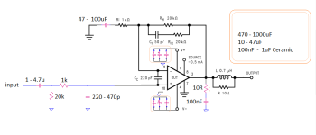
What I managed to do instead, until now, on Kicad is this:

It feels a little like cheating, but I found this guide on the internet:
https://www.circuitbasics.com/design-hi-fi-audio-amplifier-lm3886/#Things-to-Decide-Before-Starting
and it seems pretty good to me, I counter-checked a couple formulas and circuits with the datasheet, nothing to say against it...with my inexperienced eye in amplifier design. (I have not chosen the values of the single components yet, I am aware of it.)
If I am not totally wrong, what I did is even the same as what you did, just that I copied it from someone else and counter-checked the datasheet.
No problem with that. Just don't plug , unplug the amp while its powered on. Do that before you turn it on. (to avoid buzz and a thump in your speakers).
Also don't forget to add the input RF , EMI filter, and output zobel.
What I managed to do instead, until now, on Kicad is this:
It feels a little like cheating, but I found this guide on the internet:
https://www.circuitbasics.com/design-hi-fi-audio-amplifier-lm3886/#Things-to-Decide-Before-Starting
and it seems pretty good to me, I counter-checked a couple formulas and circuits with the datasheet, nothing to say against it...with my inexperienced eye in amplifier design. (I have not chosen the values of the single components yet, I am aware of it.)
If I am not totally wrong, what I did is even the same as what you did, just that I copied it from someone else and counter-checked the datasheet.
I am aware of that too, but I really like the topic and my ego/curiosity does not allow to just by the finished product...I want to build it and own it.Now I also see that Ali Express has some very nicely priced (stereo) boards built around the LM3886. Those are prices I am totally unable to design and have PCB made, buy all the components and the heatsink. The heatsink alone is usually half of the total price. And since nowadays mainly complete assortments of active components are offered (of which 80% I'll never use, talk about waste!) I would not able to build this board myself for a price even close to that. Even if the board contains some fake components they are easy and cheap to replace.
C12 you could use non polarized cap or if you use polarised, + should go to ground for LM3886 because of its internal schematic.
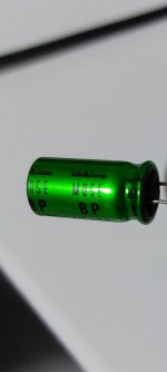
You can buy Nichicon Muse BP one of the best caps for audio .( the green ones)
For input cap C8 you can get a film cap, non polar.
You can buy Nichicon Muse BP one of the best caps for audio .( the green ones)
For input cap C8 you can get a film cap, non polar.
Attachments

I had the TDA7294 , DMOS , it sounds good but the mids and highs to bright, to me . ( it had power, I abused it on +-40v on a 12 inch sub as well, no complaints on bass , it didn't die even when run hot ) Maybe the TDA7293 sounds different ? I don't know.was planning to buy some TDA7293/94 boards as mid and hi amplifiers for my active speaker system. But these LM3886 circuits also look very nice. Any comments on which to prefer?
LM3886 sounds better imo.
Of all the chips I tested LM3886 and TDA7375 sound the best .
Hello again,
@xXBrunoXx
on your schematic example you left the mute pin open, do you put any components or a switch on that input or do you leave it just like that?
@xXBrunoXx
on your schematic example you left the mute pin open, do you put any components or a switch on that input or do you leave it just like that?
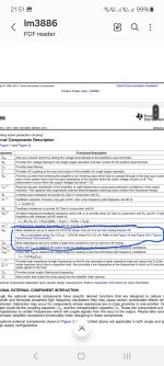
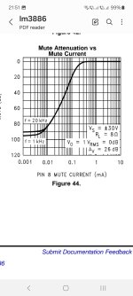
Hi, you need around 0.5mA on the mute so the amp turns on , unmutes.
You need a resistor fron mute to -Vcc , with a cap from mute to gnd. Look in the datasheet.
RM = 54.8k so a 51k res would give around 0.5mA at -30v
27k for RM would work for 1mA at -30v .
You need a resistor fron mute to -Vcc , with a cap from mute to gnd. Look in the datasheet.
RM = 54.8k so a 51k res would give around 0.5mA at -30v
27k for RM would work for 1mA at -30v .
Attachments

- Home
- Design & Build
- Electronic Design
- DIY PC/Desktop Setup