Anyone know if there are DIY examples for SiC JFET amps? Low power stuff is fine, mainly looking for a headphone amp option (35R load, sub 5W).
Tube guy here, all that black stuff is abracadabra to me 😉
Tube guy here, all that black stuff is abracadabra to me 😉
Last edited:
I have experimented with the UnitedSiC UJ3N065080K3S power JFET in a couple of different power amp designs. You can read about it here:
They are low parts count amplifiers and uses choke loading, so that might appeal to a tube guy. You can easily simulate these circuits in LTspice and modify to meet your requirements. Or, it would be easy to breadboard an amp and experiment.
There is also the LU1014D power JFET. Lots of posts on diyAudio about this device, which can be quickly found with a search.
I have been at a bit of a standstill waiting for aluminum SMD adapter PCBs for my Lovoltech JFET projects and I was feeling bored, so I started looking for another power JFET to play with. After a bit of research, the UnitedSiC UJ3N065080K3S seemed like a good candidate to explore since I could not find a lot of info on its use in amplifiers. So, I found a LTspice model and fired up my favourite computer game and started to play.
I modeled a source follower power amp first and it appears that 20 watts output would not be too difficult. I think the Lovoltech JFET may be better...
I modeled a source follower power amp first and it appears that 20 watts output would not be too difficult. I think the Lovoltech JFET may be better...

They are low parts count amplifiers and uses choke loading, so that might appeal to a tube guy. You can easily simulate these circuits in LTspice and modify to meet your requirements. Or, it would be easy to breadboard an amp and experiment.
There is also the LU1014D power JFET. Lots of posts on diyAudio about this device, which can be quickly found with a search.
That's a great project and read. So small at that power level, tube amps are ******* boat anchors in comparison.
The 120W dissipation might be a bit much for me, love the PC coolers though 😀 I don't need more than 1W at 35 ohms load, not sure the UJ3 is fit for my application. I mean, it will do it, but give off more heat than a tube amp 😀 I'll read through it in more detail.
All the JFETs I see named, in your posts and pretty much everywhere else, are no longer produced. There are a ton of them from chinese sellers on ebay, but somehow I feel those are just relabeled imitations?
There's this one...
Attached is a photo of the first proto of an SE amplifier( the "SiC Puppy") using the Semisouth 085 silicon carbide JFET in the output stage. The front end uses the Supertex DN2540N5 depletion mode mosfet. I choose the Semisouth part over the IXYS depletion mode parts due to the extra headroom afforded by the 1200V rating, allowing me to choose B+ voltages with a bit more freedom. The circuit (to follow) is set up just as if the two parts were pentodes, with partial feedback from the output drain to the input drain, plus a limited amount of global feedback (disconnected at firtst. I used...
Actually it looks like they are available from Mouser. Onsemi just bought Qorvo and ate their SiC JFET product line.
I was able to view the datasheet from the Onsemi website - the closest I can get is their 70 milliohm part, which has a 1200V drain rating..
I was able to view the datasheet from the Onsemi website - the closest I can get is their 70 milliohm part, which has a 1200V drain rating..
Last edited:
This is the datasheet for the 70 milliohm part:
https://www.onsemi.com/download/data-sheet/pdf/uj3n120070k3s-d.pdf
https://www.onsemi.com/download/data-sheet/pdf/uj3n120070k3s-d.pdf
is the 31mR 1200V version worth it over the 1200V 70mR or the 650V 80mR? I can get all three here, but price rises but 100% each step 80->70->31 🙂
I'm ordering some parts anyway, could add a pair or two to my order.
I'm ordering some parts anyway, could add a pair or two to my order.
I dunno - I found the original Semisouth 85 milliohm part I used in my original amplifier design somewhat challenged in the junction - to - case thermal resistance department (only 1.1 degrees C per watt). I solved that issue by mounting the parts on aluminum heat spreaders with a fan-cooled heat sink intended for a microprocessor.. The onsemi part looks a lot better at a nominal thermal resistance of 0.45 degrees C per watt, so it should be a lot easier to provide proper heat sinking.
Last edited:
I don't need 100W+, just looking for 1-2W into 35R. not sure the UJ3N is a candidate, but heat should not be a big problem in my case (large passive heatsink should do?)
The 80mR are €8 each here, so no biggy if I don't end up using them. The 31mR is €26 each, hence the "is it worth it".
The 80mR are €8 each here, so no biggy if I don't end up using them. The 31mR is €26 each, hence the "is it worth it".
I was looking at what Farnell has in stock here for those UJ3N versions in regard to the milliohms, all the low R ones happen to be 1200V types. Not shy of high voltage, but not exactly looking for a 1kV design 🙂
Looking at the datasheet now; it's a whole new learning curve trying to figure out jfets and their curves, where to bias them Ug, voltage/currents
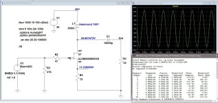
Being a brute force type of guy, based on my experience with the UJ3N065080K3S, I just simulated a variation of one of my prototyped amps for lower power output into a 35 ohm resistive load.
The attached results is for 1 watt output into 35 ohms with 0.15% THD. Frequency response at 30 Hz is down about 0.5 dB. Dissipation of the JFET is about 17 watts. Bias current is about 900 mA with Vds = 19V.
It would be easy to breadboard such a circuit for experimenting.
The attached results is for 1 watt output into 35 ohms with 0.15% THD. Frequency response at 30 Hz is down about 0.5 dB. Dissipation of the JFET is about 17 watts. Bias current is about 900 mA with Vds = 19V.
It would be easy to breadboard such a circuit for experimenting.
Attachments
Wow, thank you! I'll download ltspice and play around with it this weekend.
I take it the 0.6H choke is the reason for the roll-off?
I take it the 0.6H choke is the reason for the roll-off?
Run Your simulation before you make that assumption - what is the choke impedance at low frequency?
- Home
- Amplifiers
- Solid State
- SiC JFET amp info