Does anyone have information regarding the Belva BB5000D Output FETs? The gate resistors are 10 Ohm.
I firmly believe:
The Output Drivers consist of 16 IRF640 N-type Mosfets.
The Power Supply is identified as STP75NF75FP, with a total of 20 units.
Rectifiers identified as MURF1620CT MURF1620CTR
If I am mistaken, please rectify my error.
The Output Drivers consist of 16 IRF640 N-type Mosfets.
The Power Supply is identified as STP75NF75FP, with a total of 20 units.
Rectifiers identified as MURF1620CT MURF1620CTR
If I am mistaken, please rectify my error.
The tutorial has 9 main types. Does this correspond to any of those?
If not, post good quality photos of top and bottom of main board and faces of any driver boards.
If not, post good quality photos of top and bottom of main board and faces of any driver boards.
9 Amplifiers? How can I locate them or where should I search?The tutorial has 9 main types
I discovered the box for this amplifier and I realized I was mistaken. The Output Drivers are composed of 8 units each of TTA1943 and TTC5200.The Power Supply is designated as 50n06, with a total of 20 units. I attempted to modify the post to correct the inaccurate information, but I was unable to do so.
I reinserted all the FETs, and during testing, it plays well for approximately 5 seconds at 2.4 amps, after which the music ceases and the amps increase to 4.5. Occasionally, it will loop and resume playing, causing the amps to decrease back to 2.4. What could be the reason for such behavior?
I received it from a friend who attempted to repair it, and he informed me that it was a BB5000D. However, I contacted him and asked him to verify, and it turns out it is a Lanza MXA284. He only provided me with the board, which I was unfamiliar with, and since it has no identifying markings, I did not question it. I apologize for this.
Thanks for the PDF, it will be handy.
With all the output FETs out, it functions properly, exhibiting no voltage fluctuations. The power supply FETs and rectifiers demonstrate effective PWM and an amp draw of 1.2. However, It operates effectively for about 5 seconds at 2.4 amps, after which the music stops and the amps rise to 4.5. Occasionally, it will loop and continue playing, resulting in the amps decreasing back to 2.4 and a faint humming noise is emitted from one of the filet coils when output FETs are in..
What could be the reason for this occurrence or what should I check/replace next?
I have inspected all output FETs.
I have replaced the 494 and 358 components.
I have tested all transistors and resistors.
What's the regulated rail voltage?
Are any transistors heating up when the current increases?
Are you starving it for current?
Are any transistors heating up when the current increases?
Are you starving it for current?
Q: What's the regulated rail voltage?
A: Middle pin of rectifiers is 38.6
Q: Are any transistors heating up when the current increases?
A: I don't see any but what's in the pictures.
Q: Are you starving it for current?
A: no, i have it set to 10 amps.
My friend mentioned that the sole action he took was to eliminate the 3 pole 8 pin switch responsible for managing the x-over FULL-HPF-LPF. Upon its installation, half of the power FETs were experiencing excessive heating. After removing it, all the power FETs now exhibit PWM behavior and do not generate heat under no load conditions. If you examine the output FETs, only half are becoming warm, with two of them reaching elevated temperatures.
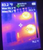
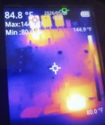
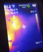
The first image depicts the power supply.
The second image illustrates the functioning half of the output, although two components are getting hotter.
The third image shows the cold half of the output.
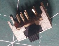
The fourth image features the switch I utilized; do they vary in function on the inside for a 3 pole 8 pin configuration like this one? Maybe its shorting something out.
A: Middle pin of rectifiers is 38.6
Q: Are any transistors heating up when the current increases?
A: I don't see any but what's in the pictures.
Q: Are you starving it for current?
A: no, i have it set to 10 amps.
My friend mentioned that the sole action he took was to eliminate the 3 pole 8 pin switch responsible for managing the x-over FULL-HPF-LPF. Upon its installation, half of the power FETs were experiencing excessive heating. After removing it, all the power FETs now exhibit PWM behavior and do not generate heat under no load conditions. If you examine the output FETs, only half are becoming warm, with two of them reaching elevated temperatures.
The first image depicts the power supply.
The second image illustrates the functioning half of the output, although two components are getting hotter.
The third image shows the cold half of the output.
The fourth image features the switch I utilized; do they vary in function on the inside for a 3 pole 8 pin configuration like this one? Maybe its shorting something out.
Attachments
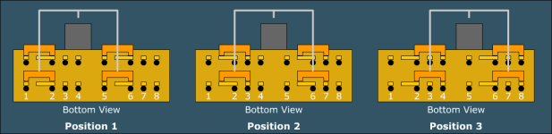
The switch should be configured like half of the ones in the image below.
It's very odd that the outputs in parallel with the ones that are heating are cold.
If you reduce the 12v PS voltage to force the duty cycle to increase to full, do the PS FETs heat up?
It's very odd that the outputs in parallel with the ones that are heating are cold.
If you reduce the 12v PS voltage to force the duty cycle to increase to full, do the PS FETs heat up?
Attachments
I managed to fix it thanks to your assistance once again. I was utilizing my microscope and thoroughly examined all the solder points because I observed that when I applied pressure to the center of the board, these inexpensive boards flex significantly. I noticed that the volume increased during the five seconds it played. While searching, I discovered a small crack on the trace for one of the TIPs situated between the output FETs, which I repaired, and subsequently, all the FETs became operational. However, it was still failing after ten seconds now. I recalled your inquiry regarding insufficient current, and to my surprise, I still had the two 4-ohm load resistors that I had previously installed on my power supply for that Fosgate amplifier and had forgotten to remove them.
Thank you once more. I hope that I may possess the intelligence as you do to resolve these issues so that I can assist individuals like you. However, at this moment, I feel that I have not yet reached that point.
Thank you once more. I hope that I may possess the intelligence as you do to resolve these issues so that I can assist individuals like you. However, at this moment, I feel that I have not yet reached that point.
Before you call it done, powered directly, reduce the 12v supply voltage and confirm that the current draw doesn't increase as the duty cycle of the PS reaches the full 50%.
Powered directly, I reduced the voltage from 12 volts to 10 volts; the amperage remained unchanged.
When doing this what exactly are we looking for?
Earlier post:
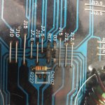
This resistor appears to be burnt, measuring 76.4 ohms.
Q: Would anyone be able to identify what this is?
A: The burnt resistor R17, it was originally rated at 100 ohms.
When doing this what exactly are we looking for?
Earlier post:
This resistor appears to be burnt, measuring 76.4 ohms.
Q: Would anyone be able to identify what this is?
A: The burnt resistor R17, it was originally rated at 100 ohms.
Last edited:
You mentioned that the PS FETs were heating under some conditions. That can be normal but with regulated power supplies, it can be a sign that the drive circuit isn't working as it should. When you lower the supply voltage, the pulse width increases (for a regulated, PWM supply) and if there is a problem, the current draw will increase. It sounds like your amp is OK.

- Home
- General Interest
- Car Audio
- Belva BB5000D Output FETs?