Kenwood KP 7010 recap

Hello,

I'm restoring a Japanese Kenwood KP 7010 and need a little assistance from someone who knows with this unit. I have the service manual which lists everything except the resistor located at R2. The main caps leaked so badly I couldn't identify the resistor by color or bands. I've attached the manual, the board schematic is on page 9.

Other than the leaky caps, a damaged dust cover and missing main counterweight I can't wait to get it running and see how it compares to my KD 5066. I appreciate any help or info someone can provide.

Thanks so much, Scott

Attachments

Why is crossover calculator spread always fixed?

I am working out the potential details of a 3-way loudspeaker, which is as follows:

15 inch woofer (solid response from 30-1000hz)
dual 6 inch mid-bass drivers (solid response from 150-ish to 8000hz
single 1 inch tweeter (solid response from 3000-20k)

Now... without getting to far into the details of crossovers (if possible)....

Why are all the online calculators for xover design LOCKED INTO a "Spread" of "8 (3.0 Octaves)" or "10 (3.4 Octaves)"?

I know, I know... the inductor will be largish.. I got plenty of wire and am not afraid to experiment with Coil64.

For the love of jesus... I want to set the Woofer-midbass and midbass-tweeter points around 200 and 5k. But these calculators only let me choose one or the other.

These midbass drivers really pack a great punch from 200 through 1000.

The Woofer (15 inch) should not HAVE to reproduce frequencies up to 400 and 600hz

Is there a reason why I HAVE to use these pre-selected "spreads"? Is there not a calculator online somewhere that lets me choose my own damn xover points?

Sorry... Just really surprised that after an hour of searching, NOBODY has been bothered by this - nor has anyone asked this question already.

-Dean

For Sale Two (2) brand new Dayton Audio RSS390HE-22 15" subwoofers

SOLD

I’m selling two (2) brand new, never used Dayton Audio RSS390HE-22 15” subwoofers. These are the high excursion model, and are no longer available. I purchased them from Parts Express in April 2023, but the project I intended isn’t going to happen. I did a rub and buzz test, plus free air impedance sweep, which showed no issues.

Looking for $480 for the pair (and will not split them up), and prefer not to ship. But will ship at buyer’s expense (37 lb. each), from Newbury Park, CA 91320. Cheers, Matt

(I have extensive perfect seller feedback on USAM, Audiogon, and eBay, same username on USAM and Audiogon, and mjbuonii on eBay)

Attachments

  • IMG_2863.jpeg
    IMG_2863.jpeg
    424.5 KB · Views: 111
  • IMG_2864.jpeg
    IMG_2864.jpeg
    434.5 KB · Views: 99
  • IMG_2865.jpeg
    IMG_2865.jpeg
    498.3 KB · Views: 88
  • IMG_2866.jpeg
    IMG_2866.jpeg
    448.5 KB · Views: 100
  • IMG_2868.jpeg
    IMG_2868.jpeg
    402.2 KB · Views: 114

Building planar magnetics for a car interior

Hi there,


I know a lot about car audio, but I am completely new to building planars. I would like to build a SQ competition car using mainly, if not exclusively, planar magnetics.

Can you think of anything that I should take into account for my development process, that might not play a big role for home audio, but for a car interior?
Things like temperature fluctuation, humidity, UV, vibrations..


The car in question is a Toyota MR2 SW20. It has a very small interior, similar to a single cab pickup. It also has T-tops, which means it's basically glass all around, so it heats up very quickly in the summer.
I live in Germany, temperature here fluctuates between -15° C and 40° C (5° F and 105° F), inside the car that would probably be -10° C to 70° C (15° F to 160° F), some sources even state up to 80° C (175° F).

Could that already cause a noteworthy degree of material expansion/shrinkage? Considering mylar would shrink with heat, while metal would expand (including the aluminum layer).

I also read that neodymium magnets can permanently lose magnetic strength above 80° C (175° F).

Does humidity matter?
What about UV?

Then there's vibrations and shaking from driving. Would you expect that to cause premature delamination? Any way to avoid that?

And lastly, since cabin gain will likely already set in slightly above 100 Hz, there will be a lot of pressurization.
Could that cause distortion? Since a mylar diaphragm is so lightweight and they will be monopoles? The Mms of a typical dynamic (car audio) midrange driver or silk dome tweeter can easily be 50-100 times that of a mylar/aluminum planar..


Any hints are well appreciated.
If there's any interest I can also share more information about what exactly I'm planning to build.


Happy listening!

NE5532 Current vs Distortion

Hi all!

I am deeply inspired by the book “small signal audio design” and am designing a preamp myself.

What keeps me scratching my head is the amount of people saying you should not load a 5532 lower than 600ohms…

15V / 600ohm = 25mA
5V /200ohm = 25mA

Do those situations yield the same distortion or is there something I am missing?
What if I need a 5532 that will never need to put out more then 5V??

If loading distortion comes from the current flown, I was also wondering what the ideal output current is for a 5532 distortion wise. As in the book he is comparing one and two 5532’s driving 220ohm at 5V.
The distortion is lowered with 2 5532’s in parallel due to the lower current per 5532 right?

Then why can’t I find a graph that puts 5532 output current vs distortion? That would be really practical in determining feedback resistors etc.

Thanks for your time!

Heat sink size.

I have a Connex amp that requires a heat sink of 1.5C/W. It will be retrofitted to a passive speaker cabinet to make it active. I would like to use a black anodized sheet of aluminium, 3mm or 1/8”. Is there an easy way to calculate the size? The amp is rated a just under 300 watts into 8 ohms and the speaker’s nominal impedance is 8 ohms.

Taramps Smart 5 diodes identification

I'm rebuilding the output section of a Taramps Smart 5.
The diodes near the output mosfets are also dead short.
I know the ic and so on, but nothing on the didoes.
I found in the forum here, that somebody used LL4148 and zmm5245b diodes.
Can somebody confirm if those ones work ? And How do I know which is which ? D10 and D32 ?

Attachments

  • 20240405_150915.jpg
    20240405_150915.jpg
    489.9 KB · Views: 79
  • 1.jpg
    1.jpg
    390 KB · Views: 81

For Sale EU Zone: 6P3SE (6L6G), 6P6S (6V6), 6N9S (6SL7GT), 6N23P (6DJ8, E88CC)

Hi !

I have various NOS/NIB tubes for sale. Shipping from Euro-zone.

Power tubes:
6P3S (similar to 6L6G, 5881) - SOLD OUT
6P3S-E (similar to 6L6G, 5881) - 10 Euro / pc, “E” variant long life, mostly 1979, Reflector factory
6P6S (similar to 6V6G) - 5 Euro / pc, 1980, Reflector factory
6P1P-EV (similar to 6AQ5, EL90) - 3 Euro / pc, 5+ pcs - 2 Euro/pc, 197x, 198x, Svetlana factory, “EV” variant long life

Small signal tubes
6N9S (similar to 6SL7GT) - 3 Euro / pc, 1973-75, Reflector factory (new low price)
6N23P (similar to E88CC, 6DJ8) - SOLD OUT
6N3P (similar to 2C51, 396A) - 1 Euro / pc, most are 198* , Reflector factory

Rectifier tubes
6C4P (6Ц4П, similar to 6Z4, EZ90, 6Z31, SV4005) - 6 Euro for pack 4pcs, 1988, Reflector factory

Prices without shipping cost. Minimum order 10 Euro net (goods, without shipping cost).

I don’t have tube tester anymore so I can’t test them. Paper packaging is often up to 48 years old and not in pristine condition, some tubes missing paper packaging.

Shipment to EU countries only, with regular post (economy) or DPD (to self-pick-up station) or address to address (2nd option is more expensive).

Payment via PayPal. When ordering please PM your destination address, daytime phone number required for DPD transport company.
For nearby DPD pick up station use this link. Once goods in pick up station you will get SMS.

https://www.dpd.com/be/en/pickup/find-parcelshop/

Due to the age of items sold as is, no warranty or return.

Photo 23-03-25 18-25-34 7202.jpg

Question about some PA Speakers

I am currently thinking about buying the VX1015BT or the VX1050BT. I want it for like a school event that will happen and like 200-300 people will be attending. The school is pretty big lets say about 80-100 meters long. Which one will be good for my pocket and give me a good performance for it. I'll also use it it my home ( for waking up the neighbors ) but mainly on events. They both don't even need a console so yea.

Question regarding the tuning frequency formula for flared ports

Hi everyone

I have been reading the paper "Maximzing Performance from Loudspeaker Ports" that covers the interesting benefits of flared ports. I really want to apply this knowledge to my upcoming project, but I am having trouble with the formula for the tuning frequency, and I am hoping that someone can help.

I have no experience calculating speaker enclosures or ports manually from equations. I have been using WinISD to do the calculations for me. With that said; It would be great if someone could walk me through the process of deriving the tuning frequency from the formula.

The paper can be found here and the formula can be found on page 32. If you are not familiar with the paper I suggest reading from "5. Study # 3: Modeling flared ports and prediction of tuning" on page 30 (or the whole paper, it's great) to get an understanding of the equation.

Other than generally not being able to get any sensible numbers from the formula (I have attached a screenshot of my calculations), I specifically have a question about the comment below the formula "The only difficulty in using this formula is finding the best fit flare radius to a given profile, but even this is relatively easy using the built in optimizers in most spreadsheet software". I don't get why any sort of optimisation is needed? If I define L_act and know that I want an NFR of =0.5 I can just solve for r_fit, or am I understanding it wrong?

Screenshot 2024-04-04 at 21.31.31.png

LiberTango, the last LCR phono (full trafos)

Hello
In attach the photo of the phono stage with LCR de-enphasis
With two active stage with tube loaded with a 5:1 trafos.
LiberTango ( song from Piazzolla) because is free from Tango transformer that are now almost difficult to find.
The full configuration is:
step-up, first stage with Sowter NI custom trafo 5:1, LCR by Eltra in Turin (Italy) , 600:15Kohm intestage (Eltra), second stage with Sowter Ni.
Then a separate box for power, two indipendent channel, Gz32 as rectifier and the possibility to use C-L (20H) -C filter or ss stabilized that I absolutely prefer
In total are 14 irons
Good results on test and listen.
This after a long run with prototypes done with full Tango irons and EC8020 stuff, same circuit topology, same electrical results ( with little differences)


LiberTango

1710344560782.jpeg


This was the Tango proto
1710344743071.jpeg


Walter

Custom speaker parallel serial with crossover

So I have made a couple of one way speakers and am trying to build my first 2-way speaker system which is going to be a center channel. The two mid/full range drivers are 8 ohms and the tweeter is 6 ohms. Now I need >4 ohms and preferably >8 ohms. I know if I hook up the mids in parallel and then hook the tweeter in series I should get 10 ohms which will work with my receiver. My issue is how will this setup will affect the crossover which I am going to be putting in, see attached for my spiffy schematic. Can I make this work reasonably or should I have gotten some 4 ohm mid drivers and just wired everything in series. I really want the extra sensitivity that the parallel mids will give so that they will better match the sensitivity of the tweeter. The crossover is a 2nd order butters worth crossover with a cutoff at 2500 Hz.

speakerwiring.jpg

For Sale Lundahl LL9206 Moving Coil Input Transformers

Pair of Lundahl LL9206 Moving Coil Input Transformers on K&K Audio PCBs

Configured for 1:10. Can be used 1:5 or 1:20

The -IN top pad is missing on one pcb, but can be soldered on the pad below

http://www.lundahl.se/wp-content/uploads/datasheets/9206.pdf

£100 including UK postage. UK only sale

Attachments

  • 20240323_154513.jpg
    20240323_154513.jpg
    410.5 KB · Views: 122
  • 20240323_154528.jpg
    20240323_154528.jpg
    386.8 KB · Views: 115

HiFi Man 1000SE High Freq Shelving Filter

My dad read a great review in Stereophile about the HiFi Man 1000SE headphones, which had dropped in price. I read online and found they were received very well and called a bargain at $2000. So, I bought them for my dad. However, I also noticed a couple of the reviews were done with the reviewer using EQ on the high frequencies and that many people found them to sound "bright" because of a 6dB high freq. peak from 6-8 kHz. My dad and I were in that camp and he and I had quit listening to them. I don't how HiFi Man let these out to market without fixing this problem. The return window had long passed so I decided to fix the problem using a passive shelving filter. While EQ in music server software could fix the peak, it didn't fully satisfy me sound quality wise and my dad is older and can't use a music server.

So, this is what I did and I could not be happier with the results! These really are amazing headphones with the peak fixed. I also prefer a down tilted frequency response, so this may not appeal to those who like a "brighter" sound. However, my dad now says his good classical recordings sound like he is right in the concert hall. Very spacious and musical and by far the best phones I've heard, with this mod. My dad/s amp is an old Headroom Blockhead - a dual mono balanced headphone amplifier.

This is best used with balance headphone amps, but could be used with single ended amps that can swing enough voltage and current. This filter drops voltage sensitivity by 4dB because of the series resistance. This HiFi Man planar headphone has a very flat 35 ohm impedance, so this mod works well here!

See attachments for schematic and pics:

Attachments

  • Filter_Pic_Closeup.jpeg
    Filter_Pic_Closeup.jpeg
    913.1 KB · Views: 110
  • Filter_Pic_Overview.jpeg
    Filter_Pic_Overview.jpeg
    1.2 MB · Views: 115
  • Freq_Response_2024-04-04 23_09_36-.png
    Freq_Response_2024-04-04 23_09_36-.png
    29.8 KB · Views: 115
  • Hi_Fi_Man_Filter_Schematic_2024-04-04_LTspice XVII - [Headphone_Filter_2.asc].png
    Hi_Fi_Man_Filter_Schematic_2024-04-04_LTspice XVII - [Headphone_Filter_2.asc].png
    25.3 KB · Views: 108
  • HIFI_Man_1000SE.jpeg
    HIFI_Man_1000SE.jpeg
    1.1 MB · Views: 113

Hello from Portland, Oregon

Hello to all! Retired electrical engineer here with a bit of 70's & 80's era audio gear I'm refurbishing. I came across this forum in my searches for information on the subject and it seemed like a good idea to revive my (very old) membership here.

My background: 40 years of doing failure analysis on integrated circuits (analog, digital and mixed designs). Due to the demands of my job I became somewhat of a generalist so I also know a bit about IC fabrication, chemistry, material science and mechanical engineering. Due to the nature of my job, I'm pretty good at taking things apart but not so good at putting them back together again!

My current refurb projects include an SAE 3CM power amplifier and a Technics SL-120 Mk1 turntable. I'm the second owner of the power amplifier and the previous owner did some ill-advised mods that I'm removing. I also have replaced all the old electrolytic capacitors and swapped out the old phono plugs with decent(er) ones.

I bought the SL-120 new. It currently has a speed regulation problem for both 33-1/3 and 45 RPMs, possibly due to leaky electrolytics (they're slated to be replaced anyway). All the potentiometers will be treated with contact cleaner, and then we shall see how it works.

In addition to old stuff, due to the fact that my old (home-made) phono preamp failed and no replacement parts were to be had, I just finished designing and building a phono preamp. It uses a pair of OPA1651 opamps. The RIAA networks are based on information I found here.

What role the opamps in this guitar amp?

Could someone explain to me the role of the various opamps in this guitar amp's circuit?
I know u4 is the reverb send/return.

The amp has a "saturation" control for overdrive gain. Is that u2?
Is this a passive EQ, not using u3?
Interested to learn about this.

What-Peavey-amps-came-with-the-saturation-knob-r-PeaveyCvlt.png

254900227-Peavey-Bandit-65-schematic.pdf - Adobe Acrobat Reader (64-bit) 3_27_2024 12_52_44 PM.png

Attachments

"Small" horn rigs based on 100Hz up folded horn

I've been playing with a 12/15 scale Klipsch Belle (18.75"H x15" D x 23.75"W along with a very high xover to whatever horn I had handy. (A B52 waveguide and DE250)

Anyhow I like what i hear from the little W-bin more-so than what I got from my Peavey FH1. I think a pair of 12/15 Belle w. midhorn and treble horn - or as two way could make for a dynamic sounding system which would be relatively compact and work in situation s where a straight midbass horn's depth is unacceptable.

Attachments

  • Baby Belle 2-way mini-horn rig.jpg
    Baby Belle 2-way mini-horn rig.jpg
    168.6 KB · Views: 118
  • BABY BELLE THROAT 1.jpg
    BABY BELLE THROAT 1.jpg
    89.4 KB · Views: 108
  • 12PE332 IN BABY BELLE.jpg
    12PE332 IN BABY BELLE.jpg
    257.7 KB · Views: 102
  • BABY BELLE SIM 12PE32 1PI.jpeg
    BABY BELLE SIM 12PE32 1PI.jpeg
    219.2 KB · Views: 107

from room to 8th order sub box? could it get loud?

i currently have a 200 liter subwoofer in a 4400 liter room. opening the door into a bigger room makes it kinda like a 6th order speaker and it sounds a lot like the winisd model i made for it. with a big spike (and a lot of wind) at 30 hertz. in the bigger room with a volume yet to be measured it gets pretty loud at the opposite corner of the door. right where it has a window. now i was wondering if i could model this as a 8th order enclosure for if the windows are open and maybe even make an extension to get other resonance frequency's. i have looked for software to model this, but didn't find anything other than hornresp which i can't seem to bet working for anything other than a horn. does any1 know what software i should use for this? or how i could use hornresp for this? thanks for reading and maybe even responding!

Onkyo TX-860 does not work

Onkyo TX-860 does not work

I have an Onkyo TX-860.
A while ago the tuner started to stop working.
Everything else was working fine.
Now it no longer turns on as it should, the whole panel and so on. Only some lights.
I would like to repair it because it has been with me for a long time and I want to get it back. Maybe a colleague who has had experience with this model can give me some ideas where to start.
I have the SM
ONKYO TX-860.png

Phono preamp: transformer separate => where goes the rectifier?

This question has been both asked and discussed here, for example here in 2003 and here in 2014. Why not do it again in 2024? I'm looking for a bit of an education on the relevant considerations, not a 'vote-by-SMS' contest to see what solution gets the most votes.

The situation is pretty straightforward. I have little room in the box with my audio PCB and consider placing the (toroidal) transformer in a separate box. This begs the question: where go the bridge rectifier and the smoothing cap? In the box with the transformer or in the box with the audio circuit? More importantly: why? Regulators are in the box with the audio circuit, this seems the easy part.

Strictly in terms of space, my preference would be that they sit in the box with the transformer. But EMI-wise and otherwise - would that be wise? I suppose the choice is between:

1. rectifying and smoothing in the transformer's box and carrying the DC through relatively long cabling (approximately 30-50cm of cable between the boxes) to the audio circuit box; and

2. sending AC through the cables and rectifying and smoothing close the audio circuit.

If choosing option 1 - is there any benefit or detriment in adding a second smoothing cap close to the audio circuit? Are there good reasons for not placing the smoothing caps a long distance from the audio circuit?

As stated in the question, the practical consideration is space. But to what extent does EMI come in to play to affect the turntable's signal? If yes, it would be a 50Hz (100Hz after rectification) problem, so not straightforward to shield against.

On a side note. Yesterday I was playing around with the (high level) design of a tie-in inverter. The outcome of some measurements made me want to know if the grid frequency at that moment was close to 50Hz, where it should be. Turns out that it was. (Using my multimeter that has a frequency counter - I don't own a scope.) It also turned out that when I took the probes out of the wall outlet (or rather, a socket in a powerstrip on my desk), the multimeter kept showing 49.99Hz. This seemed odd. After having briefly investigated, the wires of my multimeter probes turned out to be inductively picking up the frequency from the powerstrip. After moving the probe wires about 1 meter away (bit less actually, but not much) from the power strip, the meter fell to zero. Moving it back just a little bit saw the meter moving up to 50Hz again. Amazing.

To those who made it this far: my apologies for this long anecdote. For those who object on grounds of relevance, I add to my question: is this phenomenon undesirable inside the box that has the audio circuit? Intuitively I'd say yes. However, I have phono preamps that have a transformer in the box without there being an audible 50Hz hum.

On the other hand: if the rectifier is in the audio box, clearly there is a cable carrying AC current that is happily radiating its 50Hz stuff inside the same box. (Not) a problem?

I wish everyone an otherwise happy Easter.

Oh, hello, there!

Greetings! Name's Jesse, from somewhere near Seattle.

I've been into DIY and audio for decades, now. Started with a little transistor radio kit when I was a kid, but kind of lost sight of the DIY side of things for a number of years. Picked it back up a few years ago when I decided to upgrade a pair of speakers. After that, it was time to try to build a pair of speakers. Still working on that one, but it was on hiatus for ahwile. Now that I'm picking it up again (and also working on a new 2-channel system), I'm looking at building the components. So, I'm researching preamps, amps, component selection, circuits, and watching a bunch of videos. Trying to decide what I want to do. Pretty sure I'm looking to make a class AB amp, and Wayne's BA 2018 preamp looks neat and apparently people think it sounds very good, but I also was looking at the AMB α10 and Akitika PR-102, and I'm having all kinds of trouble picking what I want to do.

Typical situation, too many choices. 😁

Cheers!

Kicker ZR360 REV F

Hello all.

Bought this amp broken to try and expand my repairs and learn new amplifiers.

The power supply and output devices test as they should with my meter reading other posts, so dont think any are shorted.

The amp draws current at idle and increases as the xover module is inserted and increases more when a signal is applied even at 0 volume.

Nothing seems to be heating up, the RCA shield fuse is open, and the TP U5-6 has 10vdc on the pin. There is also 10vdc on the L+ bridging terminal.

I used the non bridging terminal negative for the ground reference with my meter.

I don't have a schematic any help would be appreciated.

Thermistor protection during brownouts

I understand closing the power switch on a toroid power source may destroy the switch if the switch happens to be closed at the zero crossing of the line voltage. A simple solution is adding an NTC thermistor in series with the switch. Its high resistance when cold will limit the inrush current and spare the switch (and provide a crude soft start for the rest of the circuit). This resistance drops to near zero within minutes. Perfect ..unless the amp is turned off and back on before the thermistor has a chance to cool. Its fine if the user is aware of this, but suppose a brownout occurs. I like the thermistor idea and its soft startup. I know a relay could be incorporated, but i like the soft startup of the thermistor. I suppose a Uninterruptible Power Supply (UPS) would solve this. Thoughts on anyone who has had experience with this?

Marantz PMD-222 not recording

Hi all, snagged 2 Marantz PMD-222 cassette recorders and they function flawlessly for playing tapes, however they do not record no matter what I do. They both seem to have the same exact issue.

I spent a few hours reading the manual (to rule out user error) cleaning the heads and pots, tested the pots, and confirmed all the mechanicals are fully functional.

The tape spins like it should when in recording mode, however nothing is being recorded to the tape. I have tried the on board mic, line in, and XLR input to no avail. I suspect this is an electronics issue as the VU meter and peak LED do not respond at all to the inputs (the VU meter functions perfectly when playing tapes).

Anyone have any ideas?

White coating or oxide on capacitors in a Denon amplifier

Has a Denon 1500 R integrated amplifier. It has been in for a service due to a bad soldering, and my service man discovered a white coating or oxide on some capacitors on the PCB. Can almost resemble white flour or sugar? Has anyone seen anything like this before? Thank you in advance!

Ikon bekreftet av brukerfellesskapet
Denon oksyd 1.jpg

Attachments

  • Denon oksyd 2.jpg
    Denon oksyd 2.jpg
    212.4 KB · Views: 94

6HZ8 and 6KT8 Marshall 18W Guitar Amplifier Design

I've worked out a version of the Marshall 18 watt amp that uses TV tubes that I have. My problem is that the data sheets for the 6HZ8 output pentode do not include optimum Load Resistance values. Can anyone please help me with how to calculate or estimate what the Output Transformer's primary load should be? Thank you! I used 12K on it as a guess btw.

Jay

Attachments

  • Like
Reactions: vinylkid58

Icepower 1200AS1 not working - pls help

Hi everyone,

I have recently bought two amplifiers Icepower 1200AS1 from you (at the beginning of may this year). Finally I had time to connect both modules and everything seemed to be working fine for the first 10 minutes, thereafter one module stopped working. And ever since it does not work. It seems that the power supply is working but the actual amplification module is not working. When I power up the module, there are weird sounds coming out of the power supply, please see the attached video. Those weird sounds stop after 20-30 seconds but nothing else happens. There is no sound coming out of the module no matter what just some hum-noise. The power supply is warm to touch similar to the working module but the amplification coil (the small one next to the output) is cold.

Can you please help if there is something I could do? I checked the connections and those are fine. This problem is there even if I change powersupply cables, or if I detach output or input cables. I even tried to disconnect it from electricity for 2 days and it is still there. I tried to measure output volts, working module has around 6-6.5v when no music is playing. The faulty module has like minus 15v which is weird.

Link to the video. IMG_0680.MOV - Google Drive

Many thanks for help.

Best regards
Tomas

B in B out?

so I've been dealing with this noise from my stereo speakers for the past year and a half or so and I know i found one of the issues its in my crossover. It's a pioneer CD-635 that I picked up from a friend and a friend of mine soldered the wires on the harness for me but must not have got it quite right because when I was rewiring some things earlier I touched the ground wire at the harness and it cut off and on so there is a short somewhere. My question is on the inside where the harness plugs in it's labeled...gnd...acc...b in....b out.. not sure I know what b in and b out mean exactly. Thinking battery but Ive not seen that before I don't think(I'm by no means a professional) and what would the acc be? I know it stands for accessory so would that be a remote? This could explain a lot of my issues

Attachments

  • IMG_20240404_005045.jpg
    IMG_20240404_005045.jpg
    174.4 KB · Views: 65
  • IMG_20240404_005102.jpg
    IMG_20240404_005102.jpg
    335.1 KB · Views: 60

Achat 118 burned | Searching a new Chassis

Good Afternoon,

unfortunately due to pretty new experience with PA systems i burned my Th0mann Achat 118 with only about 20hours of playtime.
Now i´m searching a new chassis for the Achat ant wanted to ask u guys if you have a Chassis that you would put in the Achat instead of the original, or would you use the original?

https://www.thomannmusic.com/the_box_speaker_185008a.htm | So that's the original Chassis that is build into the Achat on delivery.
Now i´m tinkering if i should the original chassis from above or something like this: https://www.thomannmusic.com/turbosound_ts_18sw700_8a.htm

Or do you have any other chassis that you would choose?
I wouldn´t put any chassis that has too much power because the old one died due to overheating (ok, he overheated because a song with about 28hz was played which didn't him do quit well)

Edit: My idea of the other chassis is also to have some more sounds on the bottom. Not for songs with 28hz but with the original chassis the Achat loos it´s power quick if something is lower than 38-40hz....it would be enough to get to 35...thats my idea.

Thanks in advance.
Givou

Why adjust 7815, a fixed-voltage regulator?

I am puzzled about raising the ground pin of a fixed regulator.

Documents at TI say you can do this but they only supply a tiny example and say little about it. Perhaps the TI fixed-regulator people don't speak to the adjustable-regulator people. There stuff should be cross-referenced. Even though documents are well-written, they need to provide some context to promote understanding.
w1.png


Why do that when a 317 will do just fine?

w2.png


I believe a capacitor is needed across R2.

w2b.png


The Whammy HPA build can configure the 7815 for 15vdc, 17vdc, and 21.5vdc. I see no benefit in avoiding a 317.

w3.png


So TI is wary of capacitors. I think it means that if you want to produce a bunch of cheap PCBs for sale on Ebay, then don't bother with capacitors. On the other if want to DIY a few PCBs for yourself and friends, then select good capacitors for careful design.

Adding filter caps to underside of PCB

Hello all Members

I posted this query in the PeeCeeBee V5 discussion thread which seems to have gone dead. Searched also with no luck.

I would like to mount 2 extra 10,000uF capacitors underneath my PeeCeeBee psu. Should I mount them on the cap pads closest to the transformer inputs or closest to the psu outs ( as shown in the image attached from member zebulo), or does it matter?

Thanks,

MM

Caps.jpg

Speaker selector switch(s) 2-way, full disconnect, 2 or 3 pole recommendations?

Setting up system with 3 different speaker choices dependent on use. DIY mains with dual subs, Old but fine ADS mini speakers with mini passive sub(they sound really well together)

Full time RV setup, desk between mains, subs in corners, mini speakers on desk with small sub under desk, just need to switch between the speakers hooked up to same amp.
I will also have a ML very good sound bar above the ceiling mounted TV on the rare occasions we turn the TV on but I can run it separately from the DAC.

Option, just a CiFi amp for the PC speakers(ADS) with or without a DAC, it will not be for critical listening but still want it to sound good.

Any known quality switch I can use for this that is not stupid expensive? I can put in a box, wire it up, etc and in fact will wire in and out cables directly to it to skip having terminals, more solder points, etc.....

Thanks,
Rick

Mullard Stereo 33 amplifier and full Kit

4626-002.jpg

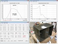
This is our new single ended Mullard stereo 33 power amplifier. It has around 3.5W RMS output per channel but with suitable loudspeakers will easily fill a room with a fantastic clear presence.
We at classic-sounds.co.uk aim to bring you a range of the highest quality designs from the 50s and 60s. We start with this classic design. Originally published as a series of articles by Mullard to sell their valves, it soon became a real hit with the HiFi community.
4626-001.jpg

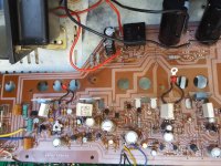
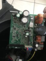
It uses EF86 input valves and EL84 output valves. We are using an EZ81 vacuum rectifier. So a total of 5 valves.
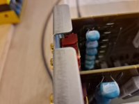
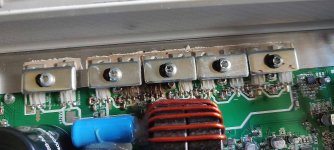
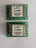
We design and make our own transformers to the highest standards.
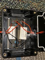
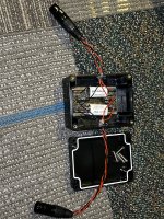
The two EF86 valves sit on a PCB and the EL84 valves are wired to the PCB.

4626-005.jpg

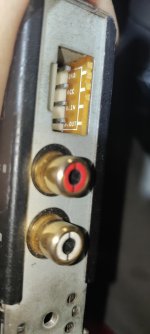
We use an ALPS gain control. Output impedance is selectable as 4, 8 and 16 Ohms.
The unit is available for US or European mains voltages.

It is available now in either a ready made version or kit form.
Just head over to https://classic-sounds.co.uk/shop
Use this code on checkout to give you £75 off PTKCRVGX
4626-003.jpg


Our customers have given us fantastic feedback, here is one example from a happy customer:

"This is a tale of the unexpected and an amplifier that surpasses my expectations, and not by any small degree.

I've wanted to try a valve amp for ages, but if you don't build one yourself or rely on one of those cheap Chinese imports, then your wallet is going to take quite a hit. But then I came across this amplifier based on the Mullard 3-3 schematic.
This fairly low powered amp (not quite flea power but not much more) cost just over £800, hand built by John Wilkinson's team at Classic Sounds (Primary Windings Ltd).

I ordered just before Christmas, and told John not to worry about keeping to the usual 10 day delivery schedule, as everyone deserves a break at Christmas and New Year, but even so just a few weeks later it arrived.
My first impression was "Wow", far higher build quality that I expected, the amp really looked superb. And the transformers, well if a transformer can be described as beautiful, then these were certainly that. The amp is not overly large, a footprint about 300mm by 250mm, but reassuringly heavy, there's a lot of weight in those lovely transformers.

I hooked up the amp to my "test system" using a couple of old speakers and the source just being my phone but I was immediately worried...was the amp doing anything, completely and surprisingly quiet, no hum, no noise of any kind in fact. After a quick heart-stopping check that I'd actually connected the speakers, I selected a bit of Dominique Fils-Amie on Spotify, and experienced another Wow moment, her voice sounded incredible, much richer than with my test transistor amp, not warmer exactly, but clean, clear and beautifully lifelike vocals, and this off a phone on test speakers.

My "real speakers" in my listening room are ones I built myself, and are a single driver design based on Frugal Horns. After allowing for a few weeks for the amp to 'burn in' (I don't actually know if this makes for any real difference, though it did for the speakers, the Mark Audio drivers needed a far longer 'burn in' time than anticipated) the amp and these speakers became a match made in heaven. Midrange frequencies are a delight on these speakers anyway (and is why I'm such a fan of single driver designs) and the amp enhanced this bringing a new transparency and clarity. Highs have improved over my other amp (a Quad Vena II Play) and bass has tightened up and been enriched. The whole experience of well controlled luscious music is an absolute delight. I play almost exclusively Jazz and Classical music (especially Baroque and single instrument pieces), this amp and speaker combination produce a rich tonality with such music, there is nothing musically that disappoints.

Is there anything non-musically that could be improved - well probably, but the price would have to rise. The volume knob works great, but the knob itself could be a bit classier. I had to find a cage to go on the top to prevent my various cats from touching the valves (though I found one for just a few pounds that actually looks great), perhaps the company could supply one as an optional extra. The amp arrived set for an 8ohm speakers (suited me fine), it can be used for other impedances, but it looks a bit scary to change for those of us with sausage fingers - though I'll bet John could supply the amp ready for whichever impedance wanted. There's only one set of inputs, so if you have multiple sources either some deft changeovers are needed (the inputs are at the front of the amp so this is facilitated) or use some form of source switching box. So, for me, not much there to worry about and anyway so very picky for an amp at this price it seems rather churlish!

This is simply a superb amplifier, in fact in my view it far surpasses the price point for the quality of sound it produces, I could easily see this amp retailing for twice or three times the price. Very highly recommended."

Marantz 1070, Loud pop on shutdown

Hello everyone. I acquired a Marantz 1070 recently and the integrated amplifier emits a loud pop when turned off, both channels. I looked at the speaker cone and noticed that the woofer upon swittching off moves in , out then in , followed by the pop. I notice also that the relay clicks off after a few seconds following the event. Otherwise the amplifier plays well. I was able to bring the dc offset down to specs and that is the only adjustment that I have done so far.

Fosi ZA3 initial subjective limited impressions vs ACA

Just unpacked it today. Very nicely packaged. Put it beside my ACA on top of my Emotiva PT2 preamp. Hooked up and turned on without drama or effort. You must press and hold in the orange volume knob until the led lights.

I like the sound, it is robust and to the point. Somewhat smeared or "veiled " compared to the ACA. ACA is cleaner.
Going to be a challenge comparing very good to excellent....

i am listening to files I downloaded from Spotify to my phone and bt'd to the E PT2. With midfi Audio Technica ear buds those files sound splendid right out of the phone.

The long and short of it is that the Za3 is never going to take the place of the ACA in my current system. I will need to monkey with the Fosi more to sum it up.

It certainly seems a great value and perfect for a mobile audio set up, electrified campsites and garages and the likes.
20240206_152652.jpg

Kenwood KA3500

bonjour , j’ai récupère un ampli kenwood ka 3500 dans un très mauvais état, en effet un coté semble défectueux puisque même en déconnectant les transistors de puissant j’ai une tension en sorti environ 30v j’ai vérifier les drivers ainsi que tout les petit transistor tout a l'air correct ????

Attachments

  • 20240301_163937.jpg
    20240301_163937.jpg
    608.1 KB · Views: 82
  • 20240302_135323.jpg
    20240302_135323.jpg
    641.4 KB · Views: 84

This project just dropped on my lap... Rebuilding Magnat all ribbon 12

Well, first a little storytime:
There is a thread on htquide about restoring crossover for magnat all ribbon 12:

https://www.htguide.com/forum/forum/mission-possible-diy/18789-restoring-magnat-all-ribbon-12

I wrote that 19 years ago, i was 20 and i didn’t know anything about building speakers..
Also that thread is a lie, i will tell you the truth:


--- I broke those speakers. ---


I lied that my friend broke them, but it was me. I was too ashamed to tell the truth by that time, but here is what happened:

-I was throwing a big party on my parent house since they were away. I usually didn’t throw parties there, but this was bit different. By the nighttime i was already very drunk, and we had moved those big speaker to livingroom.

I wanted bass.
We already had good bass, great bass from those two 12 inches, but i want more. I wanted insane bass, i wanted to impress some girls so i picked up subwoofer from downstair and carried it upstairs.

Since it was ht-sub, there was no way to connect it to my pass labs amplifier, but i didn’t let it stop me.
To this day i cannot remember what kind of idea i had, but i cut some cheap speaker wire and did some insane connection to try to make it work.

My magnats were fried in seconds.. There were sparks from connections and smoke, i cut the power but it was too late, here was the crossover:

ddd1.JPG


Anyway, i tried to fix it but i guess the midwoofer and tweeter were fried, or i couldn’t make proper connections since it didn’t sound very good with new crossover ,and i gave it to my friend years later for subwoofer use and forget about it.


Yesterday, my friend called me:
He didn’t need my magnats for his studio space anymore, and were throwing them to landfill if i didn’t need them anymore, so i said yes.

After 19 years they are back to home, and this time i have parts & measurement gear & knowledge to actually rebuild it.
I will make this fast as i can, usually my project take longer as i mull and try different things, but this time i have new midwoofer + tweeter ready, and box. is already built..

Damn..

Screenshot 2024-01-29 at 18.39.08.png

Kicker ZX750.1 overcurrent problem

Merhaba diyaudio ailesi
Yaptığım incelemede besleme mosfetlerinde ve çıkış mosfetlerinde herhangi bir soruna rastlanmamaktadır. Çıkış sürücü transistörleri sağlamdır.
Benim cihazımın sorunu lm361n söktüğüm zaman güç led yeşilden kırmızıya dönüşüyor ve bunu devamlı tekrarlıyor.
Ama lm361n takılıyken güç ledi yeşil olarak sabitleniyor ve röleyi açmıyor ve cihaz aşırı akım çekiyor besleme mosfetleri ısınmaya başlıyor.
7912 ile 7812 söküldüğünde röle açılıyor.
LM361n den şüpheleniyorum başka nereye bakmam gerekir yardımcı olabilirmisiniz.

  • Poll Poll
Playing Audio CD: The Hardcore Way

How hard it would be?

  • Easy

  • Doable but will take some time

  • I want to see you fail on Reed-Solomon decoder implementation

  • Impossible


Results are only viewable after voting.

After watching Technology Connections video about audio CD:

Login to view embedded media
I thought that it is actually not that hard to decode raw bitstream from an audio CD to get audio samples.
How hard could it be anyways, it is technology from more than 40 years ago, right?

So I started looking into it and first obvious things to do were:
1. Get an old philips CD player so I can get access to raw signal from the laser head
2. Read the redbook standard
3. Implement the decoder

Looks quite straitforward.

The first item was easy - I happened to be in the Netherlands so I got old Philips CD-160 at nearest kringloop for 15 Euros.
Second one is available online:
https://archive.org/details/RedBook...stemIEC60908SecondEdition199902ISBN2831846382

The video actually does a good job of explaining the high-level picture. Some diagrams do look horrifying at first:
decoder.png


But actually it is just a bit of data manipulation and two Reed-Solomon decoders.
decoder_simplify.png


And also I'm wondering, how many community members are interested in such experiment? 🙂

A Lateral MOSFET Power Amplifier Design (second try)

Hi,
After my first experience with a design from one book, design that has been declared on this site to be very bad and buggy, I started to read a second book; "Designing Audio Power Amplifiers", from Bob Cordell, specially the whole chapter on MOSFET.

The preceding, (read the bad) design is completed and tested with good starting results, except for an oscillation that, in my opinion, come from one MOSFET that I had to twisted the Drain and Source pins with wires after an error on my PCB. I decided to relay this circuit board as a prototype. For it's history:


Now I am ready to start over from the beginning with a new design from Bob Cordell book. My choice would be, from his suggestion, the IPS and VAS design of figure 9.20 and the OPS design from figure 14.17, and build them so I could use all my actual parts, same cabinet and Heat-Sink, same PCB mechanical dimensions on the Heat-Sink, same transistors, high power resistors, etc...

For those of you who have already tried these designs, do you have any concern about their schematics that I should be aware of, before I am starting anything?

Regards,

Linsley-Hood 75 Kit Amp Assessement

I've inherited this Linsley-Hoody 75 amplifier.

All of the glass fuses were blown, and most of the power connectors coming off the transformer have come off.
No idea where to reconnect them, the only LH 75 documentation I found on the web doesn't seem to match up at all with this kit.

are these good to listen to these days?

any thoughts appreciated, probably it's going back in the loft, on it's way to a skip in 20 years.

IMG_20240320_194150.jpgIMG_20240320_194118.jpglinsley-hood-75-07.JPGlinsley-hood-75-01.JPGlinsley-hood-75-08.JPGgoing


Is this sort of thing worth restoring?

Problems with Denon DRA-825R - setting needed

I just repaired a power amplifier in a DRA-825R and upon further inspection I saw a defective trimmer pot. The yellow rotary slider for adjustment was missing. I have now exchanged it for a new one, but I can't find anything in the manual that indicates a setting on the VR506.
I thought it was for the DC balance, but a DC meter connected to the outputs shows no change when turning the trimmer pot.
Does anyone have any idea what value needs to be set?
Greetz,
Elektroniklurch

Attachments

  • VR506.png
    VR506.png
    46.9 KB · Views: 148

100W amp speaker to line out help

I have an old 100W PA amp with spring reverb in it. I want to tap it so I can directly record the output. The amp doesn't have line out or headphone out. I could do the voltage divider mod using resistors, in my case I guess about 33k and 1k on ground. But I'm not sure if using something like non-polar 10Uf cap behind the resistors wouldn't be safer way to go. In my opinion it would stop any power peaks (switches pops etc) or what ever the old amp might produce and protect my mixer. But I think the cap could cut some high end which wouldn't be too good. What do you guys think would be the best way make it safe?

Pearl 3 power supply

Hi,

I am buiding the pearl 3 and it doesn't start very well: on the power supply, I have only D4 that lights up (not D3 nor D5...). I checked them with a battery and not only they light up, but the are soldered correctly...
Moreover, I have +/- 24.4 V on the outs (where i should have 20 V) and no continuity between the "chassis" hole on the board and the ground outputs... I have continuity between the "chassis hole" and the ground on the PCB (left empty) , and on every srews...
what did i do wrong ?

Probably dumb question …

Hi everyone,
Screenshot 2024-04-03 at 09.15.45.png


I am using an old MacBook to put a digital stream through a USB input on a small cheap DAC.

I am considering changing the MacBook for a better streamer and wondered about the input, as the streamer I am looking at has only optical or Coax digital output.

So my dumb question is

Does the USB connection just take +ve digital stream, and GND (ignoring 5V as it's powered by AC adaptor) and so I could make a simple connection that takes the digital signal from the Coax in a streamer and patch it into the digital signal connections in as USB cable/connector?

Is there anything different about the digital signal?

Thanks!

Burson Soloist 3XP Inductors

Hello,

I need to replace the inductors for the Burson Soloist 3XP. One is marked "4R7", which is 4.7 µH. And 6 are marked "100" which is 10µH, it think. They measure about 11mmx11mmx8mm. The pcb pad space they are mounted to is slighty larger about 12.5mm.

Can I replace them with ANY SMD inductors with the same 4.7 µH and 10 µH and roughly the same dimensions??? Such as Coilcraft or Bourns or Wurth Elektronik:

https://www.digikey.com/en/products...e3X8PUWN72dZA27SLyf0Kx4OXDxdOBrxoCoi4QAvD_BwE

https://www.digikey.com/en/products...e3X8PUWN72dZA27SLyf0Kx4OXDxdOBrxoCoi4QAvD_BwE

I am completely new to this DIYaudio so I'm still learning. My multimeter did not maintain a proper voltage level when testing the inductors but other components seemed to be ok...

The amp died when I left it on and i think it overheated (after I modified the opamps to Sparkos SS2590 and left the cover off and had a cardboard box sitting over it, heat dissipation problem Im guessing). The power button is lit when plugged in but the amp does not turn on when pressing the button. However the amp did work perfectly with the sparkos ss2590 for the first 5-6 hour listen, but then I left it on the next day for 8-10 hours, thats when the problem began.

Any advice is greatly appreciated. Thank you.

Attachments

  • IMG_20240319_085637.jpg
    IMG_20240319_085637.jpg
    423 KB · Views: 142
  • IMG_20240319_085602.jpg
    IMG_20240319_085602.jpg
    574.5 KB · Views: 135
  • IMG_20240319_084846.jpg
    IMG_20240319_084846.jpg
    430.6 KB · Views: 132
  • Burson-Soloist-3X-Performance-Standalone-Headphone-Amp-9_3c7912af-1969-49ed-87cf-75ded62d5ae7.jpg
    Burson-Soloist-3X-Performance-Standalone-Headphone-Amp-9_3c7912af-1969-49ed-87cf-75ded62d5ae7.jpg
    183.4 KB · Views: 127

Reconing a pair of S-20005 speakers?

Hi all! I recently got a pair of 10” S-20005 speakers that were taken out of a Gibson GSS-50 for free.

Here’s a link to the type of combo amp they came from: https://reverb.com/item/3340005-gibson-gss50-c-1966-black

Not particularly sought after, I know, but seeing as they were free I fancied trying to recone them and building my own little cab with them as a fun little project. The owner was just going to trash them and I hate to see vintage gear go to waste so I’d love to see them brought back to life again.

This is my first rodeo, so I have no idea to start, any pointers would be much appreciated!

I’ve been looking at 10” reconing kits, but my first question with this is: can I/should I just buy any 10” kit? Or should I be trying to repurpose an older 10” speaker? Would that even work? What is the general consensus on doing this kind of thing?

Obviously with them having some age, I want to stay as true to their origins and materials as possible, where possible - although I don’t really have the cash to go for something like a full, ”authentic” restoration.

And I know maybe it doesn’t matter so much as these aren’t so valued, but I’d like to learn and as much as possible treat this as if they were so that I can take the skills and approach I gain from doing this into future projects where the providence of the item is maybe a bit more important.

So…yeah. Any advice/suggestions on where to go for info/parts would be most welcome! Thanks! 🙏🏻

Auto sensing on/off switch

I am not sure if this is the right sub-forum, but I couldn't find anything better, so...

I am looking for a switch that senses the line-level audio signal, switches on an amplifier when there is a signal, and turns the amplifier off when there is no signal for a while. Yes, there is the Rod Elliot #38 circuit, which does exactly that ("Signal Detecting Auto Power-On Unit"). However, I am too lazy to make a PCB for it. I was hoping to find a complete board somewhere, but so far I couldn't.

Any hints or suggestions?

Novice Question: Adding a subwoofer in parallel?

Hi all! I’m putting together a budget system to act as monitors for mixing music.

I have 2 x Alesis Studio One MK2’s, that each have an impedance of 4ohms, and I have a Pioneer VSX-9500S receiver which can power those monitors at 4ohms.

I am being given a B&W Acoustitune sub for nothing that I would like to try adding to the system, but I wanted to check to make sure that I’m not going to blow my receiver.

The Acoustitune has what I think is called “high-level” connections, so it connects directly to the receiver via the 4 +/- L&R “A” output terminals, and then feeds the signal from that sub to each of the monitors.

I seem to have found conflicting information. The sub states on it that it has an impedance of 9ohms. Would wiring the speakers and sub in this way actually end up lowering the impedance and potentially causing damage to the receiver?

Thanks In advance!

Counterpoint SA-5000 phono stage problem

Hi first time posting. I recently picked up a lightly used Counterpoint sa-5000 tube pre-amp. The line stage sounds great and kinda throws shade at my restored Threshold Sl-10
. BUT I can't seem to get anything from the phono inputs. I tried changing the phono and rectifier tubes but still nothing- just inky black nothing. All the leds on the board are green except red led 210 on the contorl board which isn't described in either the owners manual or service manual. Any ideas?

AGC for compression using LDR and LED

Just learning about compression for guitar. First used a Jfet but it has limited range and can create significant distortion (even for guitar) when signal over 400mV. I have had really good success with LDR photo resistor and LED as an alternative to Jfets.

Also -- one of the problems with compression -- when there is no signal gain is max and that causes initial response from incoming signal to pop before loop can respond to attenuate. I found that fast attack circuit works well but need to sense both positive and negative crests of signal. Sensing both phases also improves loop response.

Anyone have experience with compression and AGC -- open for ideas.

Tweeter split in half - help!!!

Hello. I dropped my (very old) RCF dome tweeter from my desk. I suppose that the glue that held the magnet was old and dried up. It separed. Is there any way I can fix it ? I have 2 part epoxy (similar to JB Weld).
Here's a picture of how it broke. For now I've put it in a bag so dust doesn't get in the voice coil gap. I really want to fix this tweeter because it worked well before the accident.
msg799714253-123381.jpg

Super old seventies design connector for DC motors - Kennedy 9 track

Hello All, and happy new year. I apparently haven't posted since 2022 but I find this hard to believe. In any case, I am back with one of my typically annoying old-technology questions that have nothing to do with audio (anymore, at least).
Can someone identify this connector type?

If it helps, it from the early seventies, as it was in a Kennedy 9100 9-track tape drive. I have searched and searched, even in an old Newark catalog from the seventies and found nothing similar. I intend to use these to preserve as much authenticity to the motor's provenance.

Thank you for your help

Attachments

  • connector.jpg
    connector.jpg
    242.5 KB · Views: 128
Projects by fanatics, for fanatics
Get answers and advice for everyone wanting to learn the art of audio.
Join the Community
507,672
Members
7,883,526
Messages

Filter

Forum Statistics

Threads
405,994
Messages
7,883,526
Members
507,672
Latest member
rooomn