Resistor power rating (derating)

G'day Guys,

A question of power rating.

I have a resistor of 820R
Passing 0.017A
Dropping 13.94Vdc

I make this a power output of 0.237W.

This resistor is dropping voltage from the 37Vdc main supply rail to a 24vdc relay coil so the power will be continuous during operation.

I've tried deciphering the derating curves but predicting the temperature rise inside the amp chassis and the temperature rise of the resistor itself is beyond my understanding.

So. As a rule of thumb, am I safe to run a 1w carbon film resistor at 1/4 of its 1w rating continuously?
Assuming of course, that the temperature inside the chassis doesn't get obscene, which it shouldn't since this is a class AB amp.

Heat Management Questions

Hello, I am wondering about a few mounting issues for transistors, resistors and heat spreader bars.
I am planning on mounting some filament regulator transistors (Coleman V9) to an aluminum bar 3/8" thick that will then bolt to an aluminum chassis. The transistors are plastic bodied. I will also be mounting an aluminum bodied chassis mount type resistor to the chassis.

Is there a need for thermal paste on these parts before bolting them down? They do not need to be electrically insulated I know.

Same question for the spreader bar to the aluminum chassis. Is a thermal past needed?

I am NOT planning on grinding the surfaces - just running the extrusions over some abrasive paper on a glass sheet. I also have enough Keratherm to use if needed. None of these parts are running over 100° F on a breadboarded amp with cobbled together thermal management techniques. (Bolted to some punched aluminum panels around 4 x 6 inches).
Thanks in advance.

SA-9900 protection circuit / biasing problem

Hello everyone,
I am writing in this forum to seek assistance with an issue I have encountered.
Recently, I acquired an SA-9900 amplifier—a machine that, in my opinion, is exceptionally well-crafted and reminiscent of a bygone era.
Unfortunately, there were some burnt output transistors and other damaged transistors on the final amplifier board (AWH037).
To ensure a lasting repair, I proceeded to replace all the transistors on this board. Since many of the original transistors are no longer available, I opted for equivalent replacements—choosing transistors with equal or superior parameters, such as hFE, maximum VCE, and VBE.
Now that the repair work is complete, the sound output is fundamentally correct.
However, I’ve encountered a problem: after some time of the amplifier being powered on, the protection circuit automatically triggers (the relay disconnects the speaker connections). Usually, after a few seconds, it reactivates.
I conducted some measurements and observed that the bias current, initially set on the amplifier, gradually decreases over time. When I measure the voltage between PIN 2 and 6 (as indicated in the service manual), I notice that the values drop from the initial 50 mV calibration to around 10 mV and occasionally even to 0 (at which point the protection intervenes).
Additionally, the initial calibration process is quite challenging because the values read on the tester (both for zeroing the output voltage and for bias current) appear highly unstable. A slight adjustment of the trimmer causes the measured voltage to deviate significantly from the initial value, eventually settling after 1 or 2 seconds.
I wonder if the choice of transistors (or a specific one) has influenced this somewhat erratic behavior, both in the biasing current and in the protection circuit.
Any help is more than appreciated !
Attached is the schematic diagram of the main amplifier board.

Thank you in advance,
Alberto

Attachments

  • sa9900.png
    sa9900.png
    551.2 KB · Views: 214

Fullrange in a small 0.3L pod. car audio

I need some small fullrange drivers (2.5" 3.0") to use them in my car, on the a pillars. That can work in a 0.2, 0.3L pod! I am thinking about the sb acoustics sb65. But the qtc in a small pod for this driver is 0.9. How bad will sound?

My second choise is peerless ne65w qtc around 0.7

I am planning to cross them around 200-300hz
What to do? I like the sb

Or what driver should i chose

Thanks

IanCanada ReceiverPI signal routing

Hi all,
I'm looking to add ReceiverPI to my Raspberrypi with Pi2AES board as I need to do digital processing on the Pi side before sending the signal to an external dac.
However, I was not able to find any information if ReceiverPI allows that type of routing.
In short, the signal should always go ReceiverPI - > raspberrypi -> Pi2AES and should never bypass raspberrypi.
Is it achievable?
Which version of ReceiverPI should I get for that? proII or DDC
In addition, I would also prefer automatic coaxial\optical switching on ReceiverPI side based on an input signal.
If auto input switching is not possible can I use monitorpi pro for that?

note: Pi2AES uses HiFiberry Digi+ driver and is a masterclock
Digital audio stream will mostly be 96Khz 24bit or 48Khz 16bit (no dsd audio)

Thank you.

S/H in DAC?

Anybody used a Sample & Hold curcuit in a DAC (after the I/V conversion, in front of the output buffer)? I have a pair of National LF398AH, does it make sense to experiment with it? I attached the datasheet. Perhaps its acquisition time is too slow for this application.

Attachments

Vox AC15C1 Schematics

The Vox AC15C1 is their reasonably priced ($800) current production 15W circuit board based version and I
finally found a schematic for it here: I'll also try to attach the .pdf in case that source is lost.
https://www.tdpri.com/attachments/ac15c1-schematics-rev-2-pdf.291408/
Posted in this thread: https://www.tdpri.com/threads/vox-ac15c1-no-sound.570181/

There's at least one error in the reverb driver, perhaps more but overall a good job, by inkomodo.dragon
not sure who this is or if they are on here or not.

I've looked at the vintage 60s AC15 and thought that the Tremolo is way too complicated and it
would be a major cost savings to make it solid state which they've done in this design.
The Reverb driver and recovery is done with OP amps for another cost savings.

There's one OP amp in the main signal path that it looks like there's no need for, or it could at least
be moved so that it is in the Reverb path only.

Here's a discussion about this amp including some mods:
Remove the 330K in front of the volume pot in the Normal channel.
Change the tone stack values to those used in the JMI version.
He does one more that adds a "mid shift" switch but not sure how that's done:
Login to view embedded media

Attachments

Round H-frame doing double duty as a diffuser?

Hello-
I am looking for advice/opinions on the feasibility of the following:
I am looking at putting together a 4 sub system using 2 AE dipole 18's and 2 CSS sdx12's in sealed cabinets. I plan to use dsp and 4 channels of amplification- not sure yet if I will go all mono or stereo. In any case, due to the configuration of the room, I originally planned to make h-frames for each of the dipole 18's, however, further thinking has me wondering if I might put them each in a sonotube mounted vertically facing downward, sort of a vertical round h-frame. This way, I could get the recommended 3' of space from the rear of the drivers to the nearest wall (ceiling in this case) and perhaps position them behind my Acoustat 6600's to use as a diffuser of sorts. Since I intend to cross them over at around 80Hz, I wouldn't have any resonance issues with a sonotube that was say, 3' tall. I could also perhaps put a slot on the bottom to make them into a slob of sorts....Any issues with this I am not thinking of???

Ortofon test record

I'm trying to measure FR of my phono playback system. I have a test record from Ortofon from 2016. It has frequency sweep tracks recorded with constant velocity.

Hypothetically, if these tracks are played by ideal cartridge through ideal RIAA preamp and recorded in Audacity, what is the expected form of the signal envelope? These are possible answers I could think of:

a) It would follow RIAA curve
b) It would be flat from start to finish
c) Something else

I already did such measurements with my cart and preamp, but the result is a bit strange, so I want to check if my interpretation is correct. I would appreciate your informed comments.

Desktop speakers?

I'm looking to build some speakers for my desktop. I don't really have any tools but am willing to buy some for this purpose.
I listened to some active speakers in the store and was not impressed. (Kali lp-8, neumann kh120)
I also listened to some passive speakers with amplifiers in audiophile stores, but also was not too impressed. I find it hard to justify spending 500€ on speakers and 500€ on an amplifier which doesn't sound much better than random 100€ used speakers with a 100€ used amplifier. And I don't want to go used as I hate dealing with people and risk getting modly or broken equipment.

I'd like to power them with something like Schiit Rekkr or Schiit Gjallahorn. Something small, servicable, okay sounding.
I don't know much about hifi, but seems to me a lot of DIY stuff you guys do here is very efficient, with normal impedance of 8+ ohms, compared to store bought speakers which declare 8 ohms but are actually 3 ohms.

Should I look for a full range or a coaxial driver? My room is quite small so open baffle is out of the question I assume, so some drivers that work in a budget easy to build enclosure would be my best bet I assume.

Sorry if this is the wrong forum location to post this in. Open to any and all suggestions. Thanks!

WTB Pair of 2SK2087C

Hi,

Looking for a pair (or 2) of 2SK2087C in order to build the Total Domination VFET (TDV) Amp from RA7 or similar amplifier that is using that output device.


These are presently hard to find but most probably some of you have extra they will never use.

Please send me a PM if you have a few spare you wouldn’t mind sharing.

Thanks
Eric

Mark Levinson No. 436 With DC On Output

Hello,

I have a Mark Levinson 436 that has 21 volts on the output.

Initially the amp had a slight pop when powering on, so I attempted to adjust the servo voltage with R1. When attempting to adjust it to below 100mv the reading was around 3.5 volts. Adjusting R1 would not reduce the voltage, but the voltage actually went up to about 4.5 volts, and would not go down from there. I replaced R1 which allowed this to go down to 112mv. It would not go below that, and now there is 21 volts DC present on the output/speaker binding posts. I have replaced all electrolytic caps on the VG board, but there is still 21 volts DC on the output.

Any help in finding the issue would be very much appreciated.

Thank you.

Just a small dimensioning challenge - discrete vintage operational amp - DIY2024

Why not recreate an ancient representative of the first integrated operational amplifiers and track down the developers?

Have a discrete op-amp at hand as a universal genius - and all this with exactly the components that you yourself consider to be the best at this point.
What could you /we conjure up from this? From an audio preamplifier to a power amplifier, to an active reconstruction filter for our countless D to A converters or even a sensitive, low-noise thingamajig for RIAA equalization - anything is possible!

Why don't we start a small dimensioning challenge,
at the end of which perhaps this year's DIYAUDIO (i.e. 2024) operational amplifier will emerge?

Here's a suggestion:

Fire away, but don't look in vintage data books and just copy - the topology is very well known and has been frequently integrated and sold as a standard, worldwide.


Kind regards and good luck,
HBt.

Attachments

  • Herausforderung.png
    Herausforderung.png
    6.6 KB · Views: 200

For Sale 26-EL12N amp

Clearing out some more shelf space:

26 drives EL12N stereo amplifier (credit to @andyjevans for the idea!)
2 chassis construction

26s are in filament bias with Rod Coleman boards
26s are transformer coupled
EL12N in triode, OPTs are Lundahl LL1664
Can add a volume pot, if needed

Power supply chassis with cLCLC for HV, first cap is a 4uf KBG-MN cap
Filament supplies are cLCLC, with the last choke in common mode
Rectifier is an AZ12

Not sure on price yet, make me an offer if interested!

Attachments

  • tempImage6xhSqs.gif
    tempImage6xhSqs.gif
    1.7 MB · Views: 183
  • tempImageeiabKF.gif
    tempImageeiabKF.gif
    1.4 MB · Views: 287
  • tempImageehh1R3.gif
    tempImageehh1R3.gif
    1.3 MB · Views: 235
  • tempImage7WqsTV.gif
    tempImage7WqsTV.gif
    1.5 MB · Views: 203
  • tempImage3ymJp9.gif
    tempImage3ymJp9.gif
    1.3 MB · Views: 176
  • tempImageD2o6A8.gif
    tempImageD2o6A8.gif
    1.3 MB · Views: 192
  • Like
Reactions: richmain and naca5

For Sale ECDesigns DI-16 DAC

Selling a lovely sounding DI-16 DAC made by ECDesigns

It uses 16x Philips TDA1543 DAC ICs running in NOS mode, and a procedure called Direct Interpolation to avoid the use of an analog filter at the analog output.

This version has S/Pdif and Toslink inputs

Asking 325€obo, will ship worldwide

Attachments

  • tempImage4Jakht.gif
    tempImage4Jakht.gif
    1.6 MB · Views: 267
  • tempImageWLTiYC.gif
    tempImageWLTiYC.gif
    1.1 MB · Views: 257
  • tempImageoRiMrF.gif
    tempImageoRiMrF.gif
    1.1 MB · Views: 248

Hifonics Brutus BXI4000D Output Gate drivers

Hey everyone... I've gotten my hands on an hifonics bxi4000d. It had some shorted output fets wich i have already replaced. It now powers up fine and doesnt go into protection anymore. However now whenever the output relays switch the output on, i get -83V on the output terminals. My suspicion is that the Gate drivers are dead.... The signal they give to my mosfets is Sometimes -12v or some horrible square wave with a huge dc offset. Sadly the markings of the driver ics are scraped off... Does anybody know what drivers hifonics might be using? Thanks in advance!

Kind regards,
Karl

Vinyl record cleaning machine

I am looking for opinions on machines for cleaning vinyl records and especially on the two main methods used, namely, with cleaning liquid plus suction, or ultrasonic bath.
We share, with my oldest friend, a large collection of records, it is time for some of them to take a good shower.
25 years ago, I worked in a store that was a reseller of the Nitty Gritty brand. https://www.nittygrittyinc.com/
Extremely efficient machines, I see that the offer has multiplied over the years and above all, I no longer have the money to buy a machine of this brand.

Easy newbie question - please help me get a good reclocker for USB in and USB out

Hi,
I use my Android phone with HIBY music Player or USB Audio Player Pro (both bit perfect with USB priority tweaks) to stream qobuz to my DACs. I have found several USB dongle DACs - you know, like the audioquest dragonfly, that sound good to me.

Some of these small DACs are pretty sophisticated: I have 3 R2R Dacs, one of which is 1-bit, one of which has a great FPGA. I have some delta sigmas with different chipsets which have their own characters. These all play into my home stereo right next to my turntable and standalone (old school bitstream DAC). I power the dongle DACs with a power brick (one of those fat mobile phone chargers) and use a USB hub to give them more power than a phone offers. I mention all of this because it sounds good and is pretty fun to be able to chabge your DAC every few days.

I am sure though, that a GOOD USB in and USB out reclocker between the phone and the DACs would be an improvement. Can you recommend such a beast ? if it has a powered USB out that would be bonus.

Most of the reclockers or USB decrapifiers tend to deal with i2s or convert from one connection type to another. I would be stoked if I could get this done with a USB c in and a USB c out with the magic done by the reclocker: (decrapifying, noise filtering, jitter reduction).

I don't want to overspend on the ifi galvanic USB or similar. they cost too much and do too little. I am pretty sure something pi related might be the best.

regards,
W

Name of this enclosure?

I saw an uncommon speaker enclosure design some time ago - here at diyaudio, I think - and would like to explore it further. But, for the life of me, I can't recall the name and haven't had any success searching for it.

Here's what I remember about it: The name of the design, presumably that of the originator, sounds European, possibly German. It has an opening at the front that starts as a narrow slit at the top and widens downwards with the sides curving away as something similar to a parabolic curve. There's a system of baffles and channels inside.

There was a link to what was obviously a scan of an old document. I've made a rough sketch from memory of what it would look like from the front. Can you please help find the reference again?

Unknown speaker.png

Good morning, I am from Spain. Please take a look at my Crest Audio CD3000

GOOD MORNING PLEASE MY CREST AUDIO CD3000 CHANNEL A HAS ACL/IGM PROBLEM PLEASE IF THERE IS ANY SOLUCION PLEASE HELP ME OR IF ANYONE HAS FIX THIS PROBLEM BEFORE IN THIS CREST AUDIO CD3000 I CAN SEND THE AMPLIFIER FOR FIX ONLY IN SPAIN 🇪🇸 THANK YOU

Attachments

  • 20240324_130520.jpg
    20240324_130520.jpg
    287.6 KB · Views: 112
  • 20240324_130547.jpg
    20240324_130547.jpg
    291.9 KB · Views: 92
  • 20240324_130550.jpg
    20240324_130550.jpg
    258.3 KB · Views: 88
  • 20240324_131513.jpg
    20240324_131513.jpg
    244.5 KB · Views: 102
  • 20240324_130459.jpg
    20240324_130459.jpg
    355.6 KB · Views: 112
  • 20240324_130453.jpg
    20240324_130453.jpg
    318.5 KB · Views: 100
  • 20240324_130520.jpg
    20240324_130520.jpg
    287.6 KB · Views: 98

Going to try OB 3-way

Yes, I'm new to this! Now that it's out of the way, I'd love some input:

I have a little open baffle project started and my plan has been to really keep the design to a minimum. I bought a pair of 3-way speakers meant for in-wall installation and going to make the baffles myself. If there is anything I don't like, I will adjust components or speakers as a learning platform.

They already have a crossover but here is what I noticed: the 3.5" midrange has a sealed basket and the 1" dome tweeter is essentially sealed too.

Does that negate the effect of open baffle??

Sanyo 2SC3503E and 2SA1381E in stock

Digikey are selling parts in the “Market Place”

“Online Only: Marketplace Products are currently only available to purchase on our website. The Digi-Key Marketplace provides access to a broader range of suppliers and products that are reviewed and vetted by Digi-Key. They are an extension of our line card that meet our quality standards. Marketplace products ship directly from their supplier and may incur a separate shipping fee. Services typically available from Digi-Key may not be available for these products.”

Among others they are selling parts from Rochester, they have plenty of 2SC3503E and 2SA1381E in stock, at the moment a lot of them.
Stock:
2SC3503E
2SA1381E

According to the datasheet these are genuine Sanyo parts, grade “E”
Minimum quantity is 925 each part at a very good price.
Maybe some would like to start a group buy or sell some in the Swap thread?


Cheers
Stein

Attachments

Neeurochrome Parallel 86 question

I listen to jazz and classical and have been thinking about powering my B&W N803 speakers with my Neurochcrome Parallel 86 that I built about five years ago. Output @ 8ohms is 60 watts and output @ 4 ohms is 120watts. Would that work? My Aragon 8000bb is currently powering the B&W N803s and I want to reduce the number of components in my systems. If the Parallel 86 will work I will sell the 8008bb.
Thanks

WTB Pair of Waveguides for Scanspeak, SB Acoustics or Bliesna Tweeters

I am looking for a pair of Waveguides for either Scanspeak, SB Acoustics or even Bliesna Tweeters.

I am putting an order into Solen next week for premium pair of tweeters so I am open to any offers for these 3 brands.

Let me know what you have to sell.

I have a US mailing address in Port Huron MI 48060 as well.
I can pay via PayPal as well.

Update My Stereo 120

Starting another Update My Dynaco Stereo 120 complete rebuild kit. My first of these had a nearly flawless chassis, transformer and cover, but of the several carcasses I have remaining, all have some rust on the chassis. Being chrome plated it is not a simple matter to restore the chassis. I looked into strip and rechrome, and it seems prohibitively expensive.

I recently came upon DALAudio‘s “Retro” series of amplifiers using a Dynaco style chassis, all new powder coated, with updated IEC power cord receptacle. Can be found at:

https://www.eprosellers.com/dalaudio-store.html

20231024_114054_resized.jpeg


Since I am replacing everything in the amp with Dan Joffe’s LM3886 based complete rebuild kit, I wanted something that looked as good as it sounds. It does require the stock Dynaco transformer be moved slightly, and the the use of a smaller GMA fuse holder, due to proximity of transformer.
20231024_113837_resized.jpeg

at this point I have located and mounted the transformer, and wired the IEC power receptacle and fuse holder. Since the C-9 cap is also close to the installed power receptacle wiring, I test fit it in place to make sure there was no interference. Everything else will be straightforward, so the next steps will be to build and install the power supply board, and associated C-12 capacitor replacement. The thickness of the chassis is a lighter gauge steel, but seems more than adequate. More to follow.

Solutions for different SPL between speakers

I'm studying winISD and I noticed that when I compare two drivers in the same project in winISD in the sound pressure tab (SPL), the sound pressure disparity is reasonably large and I would like to know how to improve this... I looked here on the forum and some websites that the use of resistors to reduce the power that would go to the driver in order to equalize the volume between them is totally reprehensible as it considerably ruins the sound quality, another solution that I was reading about was crossovers (which is the one I think about most). I was thinking about the work that I could also use to use equalizers to send more bass signal, for example, to the subwoofer or even reduce the signals from the midranger and tweeter, but thinking about it I think that wouldn't be a very good solution.
1715788638734.png

Active crossover by using a class D power amp itself as an opamp

I have a Class D 60W amplifier by Allo and a tweeter that needs to crossed over with a 2nd order filter at 2500kHz.

Normally to do this, one might use an active filter in the input of the amp like this :

normal-circuit-png.1311682


But what if we use the class D amp itself as the opamp to create the filter? like this:

Proposed circuit.png


Would this work fine? has anyone done this? What could possibly be the cons of doing this?

Attachments

  • normal circuit.png
    normal circuit.png
    17.8 KB · Views: 511

Darlington rangemaster Ge to Si

Hi all, I have been rocking this darlington rangemaster circuit for at least half a decade now and I am tired of replacing the germanium transistors bi-annually. I installed some 2n3904 in place of the MP44s I usually use and the circuit just sounds extremely "farty" and not in a good way. There is consistent signal but just really distorted in a bad way (like way worse than the difference between Ge and Si would give).

Changes I have made to the attached circuit (and used for years): took RC out for maximum gain, RD is 15K and RE is 3.3k.


Any thought what could have gotten messed up?
darlington.png

Sonido SWR 200 FC with SEAS L26ROY WAW

I'm trying to design WAW with SEAS L26ROY and Sonido SWR200 field-coil.

As I would like to be able to experiment with different enclosure types for Sonido (or even different driver in the future), I want to make it as modular as possible.

Right now I want to build an enclosure for SEAS and I will probably start experiments with Sonido on open baffle. This will probably mean XO around 300 - 500 hz.

The question is: what kind of cabinet for SEAS?

I want it to (in order of importance): sound as good as possible, integrate well with different designs, extend low, have an acceptable WAF factor.

Seas cabinet will work as a "stand" for a Sonido cabinet / baffle, so it needs to be reasonably low.

I've read lot of threads and ideas and I started simulating it in Hornresp. I've tried classic tappered TL, BR and MLTL. I've tried to make it as flat as possible and got rid of first resonance.

Tapered TL in my view, has a resonances way to low, not sure if I will be able to got rid of them with stuffing:
TaperedTL.jpg
TaperedTL_resp.jpg


Is BR model really that nicer in reality in comparison to MLTL? Or is it more about model not being simulated that precisely? Volume and "port" are intentionally made similar at this point:
Ported.jpg
Ported_wo_fill.jpg


What I'm a bit nervous about, is bass drop in MLTL with stuffing (red line on Hornresp simulation) in comparison with unfilled MLTL (gray line). Will it be that bad in reality? Also the resonances bothers me a bit:
MLTL_schema.jpg
MLTL.jpg
MLTL_w_fill.jpg
Nakres.jpg


Still I'm leaning in MLTL direction.

Any ideas about design in general? Should I try something else?

Seas will be powered with class D in the moment (TI3255 EVM), Sonido with class A DHT / Firstwatt F4 combo. XO will be line level. DSP in the beginning, than probably done with discrete components / filters.
I'm attaching all those simulation and basic schema.

Room is about 50 sqm ~ 500 sqft, speakers will be placed about 1,5 m ~ 5 ft from back wall.

Kind request of help _ basic but low THD discrete buffers

Hi ! i am just a beginner and please be free to move this thread to a more proper location 🙄
i have a question about bjts buffers
Is it possible to get low THD buffer from very basic discrete circuits ?
I am attaching an example of what i mean
I am noticing that using a npn and a pnp together instead of using just one bjt as a common collector there is a sort of THD cancellation ?
Is this a general effect ?
I have already a schematic of a decently low THD buffer ... if i add another branch mirroring it (i.e. replacing npn with pnp and viceversa) could i get even lower THD ?
Thank you very much to All
gino

Attachments

  • bjt pair buffer.asc
    bjt pair buffer.asc
    2.6 KB · Views: 83
  • buffer fft.JPG
    buffer fft.JPG
    144.6 KB · Views: 72
  • buffer two npn _2nd.JPG
    buffer two npn _2nd.JPG
    153 KB · Views: 62

Colour coding component mains leads

I have a Cyrus system comprising
CD player (used as a transport)
DAC
Pre amp
Smartpower amps x3 (yes, I'm tri-amping)

Each of the above has a PSXR (a power supply that is supposed to be an upgrade to the one inside the component it connects to).

All of the above sits in 2 Cyrus Hark racks which each have a power strip for the mains cables.

The mains cables are typically 1.8m long but probably don't need to more than 0.5m, if that, so round the back it's a bit messy, add in interconnects, MC-BUS cables, it's a rat's nest. All the mains leads are IEC and black (the DAC may be figure 8 type)

I'm looking at getting shorter mains leads in a variety of colours but have not decided on the colour scheme hence this post.

1. Colour code by component, e.g. PSXR black, smartpower green, CD red etc.

2. Colour code by function CD + PSXR black, HF smartpower + PSXR green, mid smartpower + PSXR red etc

3. Colour code by position. There are 8 different cable colours, a colour indicates component position on the rack. Shelf 1 = black, shelf 2 = red, shelf 3 = orange. If the leads were available in brown, then I could use ye olde resistor colour code. Obviously using C language indexing, starting at 0 (black).

I am favouring scheme 2 and 3, reason for the colour coding is if I pull a plug, I know immediately which component is affected..... but it wouldn't be that big a deal to follow the lead.

Anyways, what do you think?

For Sale SEAS FA22RCZ

I'm selling the legendary Seas fa22rcz, outstanding full range for infinite DIY projects, horn loading, reflex, closed box, open baffle, etc. Excellent aesthetic and perfect electrical-functional condition, very slight aesthetic defects due to exposure to light (in the photos you can see a small shadow created by the whizzer). Price of the new € 480 per pair. My request is € 249 + shipment only in EU. For any questions just write me.

Attachments

  • IMG_20240514_085357.jpg
    IMG_20240514_085357.jpg
    310.8 KB · Views: 70
  • IMG_20240514_085211.jpg
    IMG_20240514_085211.jpg
    525.8 KB · Views: 74
  • IMG_20240514_085335.jpg
    IMG_20240514_085335.jpg
    262 KB · Views: 68
  • IMG_20240514_085304.jpg
    IMG_20240514_085304.jpg
    293.7 KB · Views: 65
  • IMG_20240514_085259.jpg
    IMG_20240514_085259.jpg
    327.2 KB · Views: 63
  • IMG_20240514_085219.jpg
    IMG_20240514_085219.jpg
    326.4 KB · Views: 69

Low or high output impedance to high end amp

Hi, I have a high end class-D pre-amp/speaker-amp set, and just bought a vintage Sony tuner (ST-5066).
The tuner offers both 'normal' (0.75V) and 'high' (1.5V) impedance outputs.
As a newby in audio, I would reason that you would let the best amplifier do most of the amplifying within the setup, so that would suggest using the normal output, and have the class-D do the heavy lifting.
However, cables to the pre-amp are 5m. I understood that long cables require higher voltage to reduce quality loss along the way, suggesting high output.

What would be most optimal, or are there more factors weighing in?

Audio source/amplifier selector with VU meters

Hi guys,
As it was difficult to me to find an audio source selector combined with amplifier-speaker selector, I decided to design my own. The design is almost finished, but I'd like to have your opinion, advices, proposals, etc., to make it really helpful and good designed. The project will be 100% open hardware. Attached are the preliminary schematic, PCB, pictures of the chassis and PCBs. The design has been made using Altium Designer 20.
Some info about GND planes.... The board is 4 layer, because I had to shield all signal tracks, even they are as short as possible, and are between audio relays and the RCA connectors. That means I have no critical GNDs. I can supply pictures of all layers, layer by layer for greater clarity. Tha chassis is standard form 430x300x70mm with two knobs - one for selecting from 5 sources, and one for selecting from 3 amplifiers. I left just one speaker output, because I have one pair of speakers. Also there are 2 x VU meter drivers because the chassis hasn't its own. The power supply is linear to avoid EMI.

Best regards
Nick

Attachments

  • Audio-selector-board-V1.jpg
    Audio-selector-board-V1.jpg
    217.6 KB · Views: 196
  • Audio-selector-board-V1-3D.jpg
    Audio-selector-board-V1-3D.jpg
    144.9 KB · Views: 181
  • Audio-selector-board-V1-Orthographic.jpg
    Audio-selector-board-V1-Orthographic.jpg
    133.5 KB · Views: 182
  • Audio-selector-board-V1-3D-angle.jpg
    Audio-selector-board-V1-3D-angle.jpg
    132.8 KB · Views: 199
  • Audio-selector-chassis-V1-3D-angle.jpg
    Audio-selector-chassis-V1-3D-angle.jpg
    22.5 KB · Views: 196
  • Arsov-audio-selector-01.pdf
    Arsov-audio-selector-01.pdf
    552.7 KB · Views: 185

For Sale ProtoDAC boards

Have two one (red) spare from a jlcpcb order using the most recent gerbers from github.

All gone.

They're free, I'll even pay for post (UK preferred) if you promise to make a small donation to a hospice charity near you. I don't need to know which hospice or how much, just promise you'll give something.

Steve

Munich High End 2024

The thrill is gone

Well, I kinda had enough from the Munich High End show, let me elaborate with some pictures, starting with my favorite room this year- Thorens.
20240509_104751.jpg


Open baffle Thorens loudspeakers-22k. Very relaxed and open sound, the kind of sound you can live with for 20 years.
The rest of the system costs like a Porsche GTS which bring me to point #1 why this post is going to be more of a rant then a cover-up.

Let's jump to the most anticipated yet frustrating 🙃 system in the show- Vivid audio moya.
20240509_102935.jpg


This must be a great speaker but I wouldn't know, they cranked the volume up so badly that I couldn't stay. More over almost everybody went full Monty on this first day which means that by Saturday most of the guys there will suffer from hear damage.

Then I went to hear the neighbor room.
20240509_103601.jpg

The room owner and designer of this very interesting looking speaker started by apologies that I wouldn't be able to appreciate the sound because the Vivid Audio Moyas 16woofers created such dominating bass that ruined the presentation for everybody else... he also told me there is a paragraph demanding to keep the level on 75db. I had a laugh

Never the less here are some exotic shapes that might inspire your DIY.

20240509_135216.jpg
20240509_134422.jpg
20240509_131322.jpg
20240509_124952.jpg
20240509_124927.jpg
20240509_124816.jpg
20240509_120741.jpg
20240509_115808.jpg
20240509_113157.jpg
20240509_111902.jpg
20240509_111614.jpg
20240509_111603.jpg
20240509_111016.jpg
20240509_110004.jpg
20240509_110038.jpg

Attachments

  • 20240509_124728.jpg
    20240509_124728.jpg
    334.8 KB · Views: 175
  • 20240509_111028.jpg
    20240509_111028.jpg
    613.2 KB · Views: 187

MidBass Horn

Hi

i am trying to construct a hyperbolic front horn. To make the construction as easy as possible, i would like to build top and bottom straight and just curve the sides.

Is it a problem, if the sidewalls get curve that way, that the distance is first getting smaller? Area will be conform to the calculated area.

Even if the 3D sketch is not 100% correct, it shows my problem:
1712606964997.png


1712607185341.png


Thanks and regards

Christian

The diyAudio Store May 2024 Update

We've updated The diyAudio Store so we can serve you better. It's been a big update! You can read more about the changes here: May 2024 Store Update

If you see something amiss, please let us know, or hold off as appropriate:

1. Content issues / out-of-date information / missing information

We've been busy re-arranging and re-writing pretty much everything in the store. We feel things are now in a place that is good enough to make the store live again, even if there is still several weeks more work to do on the content side of things. If you see some content issues (such as out-of-date information, missing information, etc), please either hold off on letting us know about it until next week or send us a private note by email to contact@diyaudiostore.com.

2. Bugs (things not working correctly)

With such a large update, there are bound to be some bugs (things not working correctly). Please report any bugs either in this thread or directly by email to the helpdesk at contact@diyaudiostore.com as you feel is appropriate. We'll be actively monitoring both this thread and the helpdesk for any bug reports.

Thank you very much for your patience this week while we performed the upgrade and update.

Replacement for Yamaha AX-1090 CPU IC106 XR895A00 IC LC6520H-4156

Hello diyaudio community. I am looking for spare part for amplifier AX-1090 broken CPU IC106 XR895A00 IC LC6520H-4156. All over the world is this part ouf of the stock. Is somebody who have this part in own inventory? If not, how is possible to transfer the original program to new IC LC6520H and how is possible to get raw data of original Yamaha program cpu before compile? Or do you have another diy solution for full CPU replacement? Thank you for help. Marek.

Cap multiplier for very quite preamp power supply?

Ok,
First of al I don't think the name of "cap multiplier" is a good choice as it's actually an RC filter buffered with a darlington transistor.
Now recently I needed a power supply for some preamps (+24v) and wasn't really sure if the used capacitance was good enough.
So i added the simple cap multiplier circuit.
Most of the time I just use an lm317 and it's adequate. Especially for opamps.
78xx is to noisy.

The lm317 is ok but it's not the best for ripple suppression.

So when testing the ripply at the output of the preamps as around -82dbu using only the lm317 psu
When using the cap multiplier this sunk to -100dbu.
It doesn't matter that much for one preamp but when summing 16 or more of these outputs together it makes a difference.
the preamps where discrete class A so not much psrr.

So why isn't the cap multiplier used more for preamps? it's not expensive to implement. Could be a nice extra for working with tubes.
I've seen it once in some older siemens transistor preamp modules.

any comments are welcome
  • Thank You
Reactions: ginetto61

SPL curve understanding, help needed

Dear friends,

I’ve got a question that in need of your help because I’ve only limited knowledge of physics of acoustics.

Forgive me, as I don’t know if this had been discussed somewhere in time…

Recently, i’m preparing to DIY a pair of full range cabinets and I’ve got a pair of drivers and its data sheet.
With some calculation with the data given, I was able to get almost exactly the same speaker driver impedance curve as provided by the manufacturer data sheet.

Upon calculating the SPL curve (only interested in Low Frequency range below 200Hz), I calculated the acoustical output power curve in front of the driver piston mounted in an infinite baffle. It is a generic curve given by the mid to low frequency efficiency expressed in SPL unit as shown below.

1715920855261.png


I plotted this curve below (Green) in superposition with the supplier’s SPL curve (Black).

1715920388562.png


My question is that why, at low frequency, is the data sheet SPL curve (Black), where driver mounted in an infinite baffle, exhibits roughly a 40dB/dec slope roll off at low frequency rather than the 20dB/dec slope roll off of sound pressure level (Green) from the volume velocity driving source of the vibrating diaphragm?

Have I missed anything? Please help!
Thanks in advance.

Yours sincerely,
KW

Dual Acoustic Elegance 15SBP-8A in sealed enclosure

I am planning on building a bass enclosure for using with various horn designs I am working on.

I have four AE SBP15-8A. 15", 8ohm, Apollo upgraded woofers at hand. When I model them in winisd for a dual woofer enclosure, I get 449,43lt volume having a Qtc of 0,703 and a Fsc of 35.93hz. This is very fitting for me. I will put Hypex FA501 on each enclosure so I can send 250w @ 4 ohm to each woofer. I plan on crossing to horns to lowest around 300hz and to highest around 600hz depending to the horn I am matching it with.

My questions are about the baffle width, shape and the enclosure edges. Should I make it as narrow as possible or should go for some gain from the baffle and make it wider. Shall I make the enclosure non symmetrical. Do I need chamfered edges? I would appreciate any input, thanks.

59L Tapped Horn

So I was playing around with these MCM 55-2421 trying to learn Horn Resp and because they always amused me and I was wondering how I could run an isobaric pair of subs in such a small horn. How to fold it? would you have to build a tube sticking into the mouth of the horn to essentially mount cone into the beginning of the horn, tube covers the motor side and allows mounting the second facing the same direction? Originally I was going to make it 4ft length in order to fit behind the seat of a single cab pickup. and still may, but any ideas are appreciated.

Attachments

  • 59L MCM Iso Tapped Horn Parameters.jpg
    59L MCM Iso Tapped Horn Parameters.jpg
    55.5 KB · Views: 118
  • 59L MCM Iso Tapped Horn SPL .jpg
    59L MCM Iso Tapped Horn SPL .jpg
    48.5 KB · Views: 123
  • 59l tapped horn schematic.jpg
    59l tapped horn schematic.jpg
    20.5 KB · Views: 122

NAIM Audio NAC 82 (NAC82) - looking for Service Manual or Schematic

A friend of me want to replace the electrolytic capacitors.
there are three variants (go to the attached images) :

1) Tantal (blue radial version) according post #12 (14) good replacement is KEMET's axial type T110 - go to
https://content.kemet.com/datasheets/KEM_T2031_T110_AXIAL_T212.pdf
2) usual electrolytics, axial, blue version (maybe BC components or Philips, probably for the mute control unit)
3) yellow axial version from S.L.C.E. - go to
https://aeservice.fr/en/product/slce/

The question rises up, which of the capacitors are critical regarding reliability and sonic performance.
If there was a circuit diagram it would of course be easy to find out.
Maybe one of the member can upload this - thank you very much in advance.

This URL's don't provide the wanted information:
https://skyfiaudio.com/products/naim-nac-82-nac82-rare-olive-style-preamplifier-naim-hi-cap-hicap
https://community.naimaudio.com/t/olive-nac82-no-serial-number-staff-build/30972/2
https://www.dastereo.ru/t/prodam-naim-nac-82-oficzialnyj-polnyj-servis/36228
https://www.ebay.de/itm/256485493815

P.S.: special parts from front PCB of control unit (go to sixth attached image and the last both images in post #13):
1) TC4514BP
https://pdf1.alldatasheet.com/datasheet-pdf/view/114285/ETC1/TC4514BP.html
Short form data in service manual of SANSUI's A-1500R (integrated amplifier)
https://audiocircuit.dk/downloads/sansui/Sansui-A1500R-int-sm.pdf
2) MCU: unknown due to being covered with a sticker with the Naim Audio logo. Program Date: 31-1-95

Attachments

  • Naim Audio NAC82 front.jpg
    Naim Audio NAC82 front.jpg
    390.7 KB · Views: 199
  • Naim Audio NAC82 rear panel-II.jpg
    Naim Audio NAC82 rear panel-II.jpg
    42.1 KB · Views: 228
  • Naim Audio NAC82 rear panel-I.jpg
    Naim Audio NAC82 rear panel-I.jpg
    401 KB · Views: 241
  • Naim Audio NAC82 main PCB-V.jpg
    Naim Audio NAC82 main PCB-V.jpg
    625.5 KB · Views: 279
  • Naim Audio NAC82 main PCB-VI.jpg
    Naim Audio NAC82 main PCB-VI.jpg
    545.3 KB · Views: 286
  • Naim Audio NAC82 control unit PCB.jpg
    Naim Audio NAC82 control unit PCB.jpg
    535.5 KB · Views: 232
  • Naim Audio NAC82 main PCB-III.jpg
    Naim Audio NAC82 main PCB-III.jpg
    569.4 KB · Views: 244
  • Naim Audio NAC82 main PCB-IV.jpg
    Naim Audio NAC82 main PCB-IV.jpg
    389.5 KB · Views: 225
  • Naim Audio NAC82 main PCB-II.jpg
    Naim Audio NAC82 main PCB-II.jpg
    348.2 KB · Views: 199
  • Naim Audio NAC82 main PCB-VII.jpeg
    Naim Audio NAC82 main PCB-VII.jpeg
    117.2 KB · Views: 197
  • Naim Audio NAC82 front-II.jpeg
    Naim Audio NAC82 front-II.jpeg
    105.5 KB · Views: 204
  • Naim Audio NAC82 main PCB-I.jpeg
    Naim Audio NAC82 main PCB-I.jpeg
    126 KB · Views: 181
  • Naim Audio NAC82 RC-II.jpg
    Naim Audio NAC82 RC-II.jpg
    52.7 KB · Views: 182
  • Naim Audio NAC82 PS-I.jpg
    Naim Audio NAC82 PS-I.jpg
    41.3 KB · Views: 154
  • Naim Audio NAC82 PS-II.jpg
    Naim Audio NAC82 PS-II.jpg
    38.6 KB · Views: 156

GRS Planar Midranges and Tweeters

FOR SALE Pair of GRS Planar 10” Mid / Tweeter Model PT5010-8 with optional Mounting Frames
Almost brand new as purchased new from PE in mid-2023; Barely broken in (30 Hours)
200Hz-8000Hz range ; 70 Watt; fs: 200Hz ; 8 ohms
c/w Free optional Mounting Frames

SOLD


Pair of GRS Planar Tweeter Model PT2522-4 with optional Mounting Frames
Almost brand new as purchased new from PE in mid-2023; Barely broken in (30 Hours)
800 – 20kHz range ; 20 Watt; fs: 800Hz
c/w Free optional Mounting Frames

SOLD


Comes with optional aluminum mounting frames

Thanks everyone!

Attachments

  • 1000006373.jpg
    1000006373.jpg
    671.8 KB · Views: 77
  • 1000006374.jpg
    1000006374.jpg
    741.9 KB · Views: 72
  • 1000006379.jpg
    1000006379.jpg
    746.4 KB · Views: 72
  • 1000006377.jpg
    1000006377.jpg
    705 KB · Views: 74
  • 1000006375.jpg
    1000006375.jpg
    541.6 KB · Views: 65
  • 1000006376.jpg
    1000006376.jpg
    738.6 KB · Views: 70
  • 1000006372.jpg
    1000006372.jpg
    635 KB · Views: 67
  • 20240517_204735.jpg
    20240517_204735.jpg
    584 KB · Views: 72

Unorthodox 2x18 slot loaded PA sub

HI Everyone
I'm Ale from Italy
My english is anything but perfect.
This is my second audio project and I know this is a strange way to do a sub.
I decided to build a sub for my coaxial synergy PA tops built in this thread with the help of many diyaudio guys
https://www.diyaudio.com/community/threads/2x12-and-1-4-coax-cd-synergy.373100/
My main limitation is dimension: 970x750x550mm ( my car trunk dimensions).
My goals are:
1- high spl that can match the tops (105-ish db/1m and about 3kw each)
2- not very low extension needed because I will use only for live rock music so from 45-50hz to 100HZ.
3-possibilty to transport and assemble secondary flare for bigger venues.

I absorbed some ppsl design principles reading a good part of the big ppsl enclosures thread here even if my design is push push.
Usually the plenum depth need to be the smallest possible but with my data I can lower the highest peak down to 100hz using deeper plenum.
no flare 6800w a re_2 data.pngflare 6800w at re_2 data.png
With 18ds115-8 I can use little box volume.
The driver chambers are separated.
The triangular BR ports are 440cm2 total (but I can modify easily) with 50m/s velocity at 6800w.
I want to create guides in the wood for the ports to shift it inside and outside and tune differently when I use 2 flare or not.
The secondary flare can accomodate the sub box for compact transportation.
PPSL NO FLARE.png
Now i would decide which position is better for left br port. (last picture).
wqoeòfjn.png

Do you see any problems in this design??
I really appreciate you opinion and suggestions!!!!

Thank you very much
Ale

Creek Audio T50 Tuner: Help with disabling RDS from printing on display.

Hi folks,

Is there a pin I can lift or easy adjustment to stop RDS from printing to the display, and only display the FM radio station frequency? I’ve attached the datasheets for the 4 ICs I found on The Control Board. unfortunately I do not have the schematics for the T50.

SAA6588T: RDS/RBDS pre-processor (pins 8 or 16 look interesting)

PIC16F76-I/S0: CMOS FLASH Microcontrollers

Holtek HT16512: Duty VFD Controller

PCF8594C-2: CMOS EEPROM with I2C-bus interface

Thank you

Attachments

  • SAA6588.PDF
    SAA6588.PDF
    184.6 KB · Views: 81
  • HT16512.PDF
    HT16512.PDF
    200.7 KB · Views: 72
  • 30325b.pdf
    30325b.pdf
    4 MB · Views: 72
  • PCF8594C_2-3139357.pdf
    PCF8594C_2-3139357.pdf
    109.3 KB · Views: 59
  • IMG_3795.jpeg
    IMG_3795.jpeg
    569.8 KB · Views: 69
  • IMG_3792.jpeg
    IMG_3792.jpeg
    568.3 KB · Views: 78
  • IMG_3791.jpeg
    IMG_3791.jpeg
    479.4 KB · Views: 92
  • IMG_3800.jpeg
    IMG_3800.jpeg
    244.8 KB · Views: 61
  • IMG_3802.jpeg
    IMG_3802.jpeg
    263.3 KB · Views: 75

TSA9840B (TinySine) Mono/Stereo Programming Issue

I have a TSA9840B (TWS/Apt-X) module I'm wanting to change from stereo to mono. I keep getting an error each time I try to connect. I've followed the instructions on the TinySine website but no luck. I keep getting a Read Config Error (unable to read product ID) has anyone been had this same error? If so, how did you resolve it?

Attachments

  • cs error.jpg
    cs error.jpg
    46.1 KB · Views: 77

Android phone. Musicplayer with EQ (on bluetooth too) that will access my Tidal

Hi good people.
Is this the right subforum?

UPDATE: HiByMusic seems to do all I requested in this post and its headline. Only used it for half an hour. Will try to remember to update if the good news changes and when I have compared it to a working Usb Audio Pro.

I have:
Tidal subscription.
An android phone.

I want:
A player with minimum 10 bands of equalisation or equally useful eq that will let me enjoy Tidal content and playlists.

Today I use the Tidal app and Flat Equalizer app. Both nice but would be nice to delete both and use only one app to enjoy my music voiced how I like it.

Flat Equaliser sometimes stops EQing. Maybe its posible to give it advanced rights to always be on and turn on at startup.
It automaticallly sence which bluetooth device is connected and aplies your prefered voicing for the device. Sadly it doesnt seem to be able to do it in the background. Maybe android expert can enable it to. -Not me 🙂

Therefore i hope to find one app that takes care of both Tidal-streaming and eq.

Cheers!

Hypex filter design

Hey,
I'm trying to install firmware and a dsp file onto some new Hypex Fusion amps. I was able to install the amp firmware but have been completely stonewalled on installing the dsp filters. When I open the HFD program I can see the correct amp firmware is loaded (version 5.7 for a FA 252) which if I'm understanding it correctly then requires a separate download to install the dsp filters? Problem is when I select the firmware update window the necessary file isn't available. I'm not used to using windows so maybe I'm not downloading the dsp files correctly? At least not storing them in the correct location for HFD to recognize? I've been banging away on this and have yet to get it right. This is probably because I'm unfamiliar with windows and hopefully is an easy fix?
Please advise if you can help
  • Like
Reactions: Amami Life

Dynamic range exhancer for an FM tuner

I recently acquired a Kenwood KT9900 tuner... it sounds really good and there are some good radio stations around, but when I turn the volume up it becomes obvious they are compressing the signal too much for my taste: Fine for background listening but disappointing when I want to LISTEN to it.

My system has a very low noise floor so there a no issues with noise and this FM tuner was well maintained and it sounds really good and quite quiet.

What are my options for expanding the dynamic range of the signal? I figure I'd put between the tuner and the preamp.

Martin Logan Gen. 2 questions

I have just bought two used panels for a Vantage / Vista. The previous owner said one loudspeaker started doing crackling sounds only when playing music, not when idling with the HV on. He replaced them with new panels at the advice of the European representative of ML and that solved his problem.

The panels look absolutely fine to me, i.e. no holes, uneven metallization, tears, dust, hairs, etc. I guess I will need to cobble up my own HV supply and step up transformer for testing while keeping an eye for a very cheap set of ML or other ESL speakers to salvage such parts.

Will the actual voltage and step up transformer be substantially different between Gen 1 and Gen 2? And between different panel sizes?


Bonus question: I understand the Gen 1 panels had an issue with the conductive coating which was maybe just carbon powder rubbed onto the mylar foil and with the foam spacers. Gen 2 should be much more durable with the vacuum deposited coating and the clear spar spacers. I read in some review that the already vacuum coated foil receives an additional coating to seal any tears intruduced by tensile stress during mounting. On the other hand, I have now come across several used Gen 2 systems that seem to have the classic problems of much decreased sensitivity and dull sound. How common is this? Are there any pics or instructions out there on refurbishing Gen 2 panels?

Carver Receiver 900 User Manual. Can find service manual, but not user manual.

Looking for Carver Receiver 900 User Manual. (NOT PM900 or other XX900, just plain old 900.) Can find service manual, but not USER manual. WiFiEngine website says it has the user manual, but new registrations are closed permanently so can't log in to get it. Electrotanya doesn't have it. Any suggestions? Thanks.

Is choosing a Woofer the same as choosing fruit at the market?

I was researching on the internet about woofers and how to use them, I saw tutorials and such.
But the main thing I wanted to know is what are the starting points to know if a woofer is good or not?
What parameters do I have to observe to know?
Is choosing a Woofer the same as choosing fruit at the market?
How do you know if it's bad or not?

Lower gain Tubelab SSE build

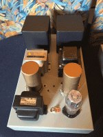
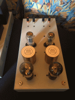
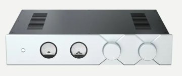
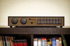
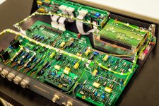
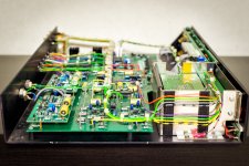
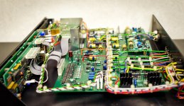
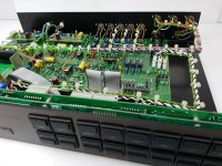
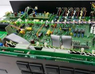
I'm planning on building a Tubelab SSE and am currently in the research phase. In addition to studying the theory behind its design and operation, I've also put together a SPICE model (ngspice to be precise), so that I can study the circuit with fewer possibility of electric shock. (Well, I'm running the simulation on a desktop computer, so there's still some possibility.)

After familiarizing myself with the basics, I though that, since I'm planning to use the amplifier with a DAC that outputs a 2VRMS signal, which seems to be way too high for the "default" 12AT7/EL34 configuration, perhaps it might be worth looking into whether a lower gain build would be preferable. At the very least, it might let me avoid using an attenuation network between the DAC and the SSE, without worrying about overdriving the latter.

In looking into this I've used the simulator (with whatever models I could find) and I'd like to double-check, some of my findings with more experienced folks. So here goes:

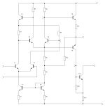
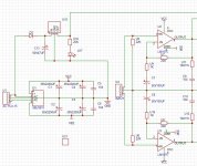
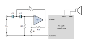
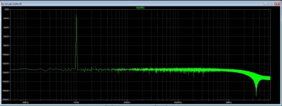
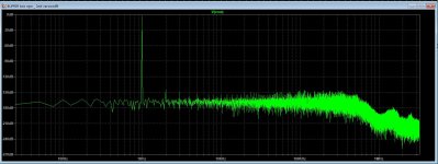
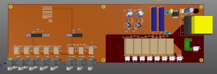
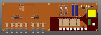
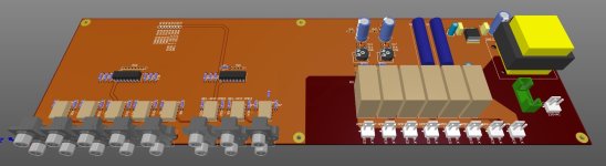
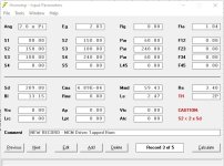
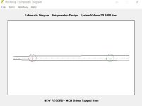
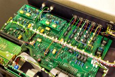
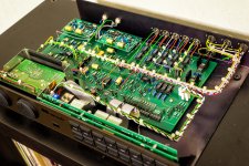
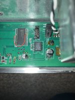
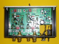
1. My circuit is attached below. As shown the B+ voltage comes from the V0 voltage source for convenience and the power supply section is not used. Results are similar when using it, apart form needing to simulate a bit longer to wait for the B+ voltage to stabilize. I'm getting "reasonable" results with it, apart from being able to get on the order of 5W of output at 1% THD from an input of about 1V p-p at 1kHz. This seems a bit low given the results posted by George on the simulations page of the SSE's documentation and also measurements from existing builds. (The output transformer has an inductance ratio that should yield a 5 kOhm impedance from the 8 Ohm load.) I understand that the simulation disregards some sources of THD (e.g. the output transformer), but I wonder if that is that the only issue, or if perhaps something is more seriously wrong with the simulation itself.

2. Assuming the simulation is more or less ok, I find that removing one or both of the bias resistor bypass capacitors, tends to yield lower gain at lower THD. Removing both C10 and C12 for instance, I seem to be able to achieve the same 5W of output as before at about 0.5%THD from an input of about 2V p-p. In both cases, the distortion is predominately 2nd harmonic with some lower 3rd and 4th harmonic components. I understand this is because the absence of bypassing effectively constitutes local NFB. Do these results seem reasonable? Is there any reason to include the bypass caps, even if the increased gain is not required?

3. In trying to reduce gain even more, I've looked into substituting the driver tube with a lower gain part. Initially I've thought about using the 12AV7, but since this seems to be relatively rare, I turned to the 12AY7. Changing R13 to 1K to get about 3 ma of cathode current and R10 to 910 for about 3V of bias, I again get about 5W of output at about 0.5% THD, but now at 3.6V p-p. The driver tube is now being driven hard and the distortion measured at its output is much higher than before, at about 1% THD, but it's almost entirely 2nd harmonic and seem to partially cancel at the output stage. Does that make sense? Is there any reason not to use the 12AY7 then? I figure, apart from needing less attenuation after the DAC, the THD+N figure should be better, since less noise will be amplified.

4. I've found some NOS Russian (or, rather, Soviet) parts locally at pretty good prices, so I thought I might look into the 6N1P-EV, or the 6N23P-EV, which seem to be well regarded. I also found a matched pair of NOS 6P3S-E tubes at the same source, again pretty cheaply and I thought I'd try that too. With a 6N1P, with associated current and biasing changes and a 6L6GC model substituting for the 6P3S-E (which I know is not the same) I could get about 6W at 0.4% THD from a 5.2V p-p source, which is close to the 2VRMS target. I then found out that the filament pins of the 6N1P are not compatible with the 12AT7 used by the SSE. Can I use an adapter to deal with this? I see some "12AX7 to 6N2" adapters; will these work? If so, is there some reason no to use the 6N1* and/or 6P3S tubes?

Thanks to everyone who's read so far; I know it was a lot and thanks in advance for any comments.

screenshot_20240513_225808.png

Aikido "oTTo" All jFET Phono RIAA Pre-Amplifier - Schematic wanted

I want to have a schematic from this FET RIAA Preamp for removing unwanted AM reception:
https://luckyx02.de/data/documents/Aikido_Phono_Prospekt_Mail-1.pdf
Der Aikido von H.-U. Otto - Lucky's Hornpage

from the MC head amp (Pre-Pre) therefore there is to find a schematic here - go to the seventh circuit under
Aikido Tube Amplifiers
Even from the tube-version of this FET RIAA preamp there are the schematics - go to
Aikido PH-2 Phono Stage
Aikido All in One.pdf - Tube CAD Journal
https://de.scribd.com/document/150411742/Aikido-All-One
http://www.hifi-forum.de/viewthread-26-12463.html (post #16)

Thank you for upload schematics from oTTo's jFET version like to see in the attached images

Attachments

  • Aikido-Phono-2-FET-Phono-Riaa-Vor-_57.jpg
    Aikido-Phono-2-FET-Phono-Riaa-Vor-_57.jpg
    453 KB · Views: 838
  • Aikido-Phono-2-FET-Phono-Riaa-Vor-_57 (1).jpg
    Aikido-Phono-2-FET-Phono-Riaa-Vor-_57 (1).jpg
    415.7 KB · Views: 766
  • Aikido-Phono-2-FET-Phono-Riaa-Vor-_57 (3).jpg
    Aikido-Phono-2-FET-Phono-Riaa-Vor-_57 (3).jpg
    143 KB · Views: 631
  • Aikido-Phono-2-FET-Phono-Riaa-Vor-_57 (2).jpg
    Aikido-Phono-2-FET-Phono-Riaa-Vor-_57 (2).jpg
    247.5 KB · Views: 708

Buzz kill

Hello, I have just rebuilt an old Playmaster Electronics Australia Mosfet amp (circa 2002 or so). Firstly I am looking for a circuit diagram, It has 6 power mosfets each channel and from memory it's 200watts RMS into 8 ohms. However I found some old circuits using 4 power mosfets that also claims to be 200 watt RMS and these have similar topography but not exactly the same . They all run on +- 70vDC rails. Anyway it basically works perfectly except when I join the minus of the inputs at any point I get a very low transformer buzz from both speakers. You have to stick your ear right to the speaker to hear it. I am on a mission to make it perfectly quiet! Chassis is grounded to mains, centre tap of both transformers goes separately to the PCB ground (0v) tracks (that track also connects directly the centres of an array of 2 x 2 x 6800uf caps per side), then single ground (0v) wires from those tracks to the centre bolts of each of the bridge rectifiers (chassis). One diagram I have has those grounds connected to chassis via a 0.1uf cap?? The signal input minus passes through a 10 ohm resistor to ground (0v) and as I mentioned above any joining at any point of that left and right signal minus creates the exact same level of buzz. Secondly the bias: currently at idle I have set about 12mv across the .22 ohm FET source resistors , though some of them are showing about half that. So I figure that is about 50ma per power FET except the ones that are about 7mv. Just curious. It is driving a pair of 1988 vintage AE1's sounds totally awesome.
Mosfet amp 1.jpg
mosfet amp 2.jpg

OPA1612 from Aliexpress, no counterfeit but why so cheap?

After working with some OPA1612 on my recent Topping PA5 D01 Module replacement project (at ASR),
a friend sent me a few OPA1612 opamps he ordered when they were in stock since i couldnt get them anywhere.
alongside with some aliexpress el`cheapos for like 2 buck a piece instead of 7..8 bucks for a genuine part.


i expected them to put some cheap crap in there, so i didnt wanna use them.
but was curious whats in there, so i opened one up.. surely they have put a tl072 or ne5532 in and relabeled it..
turns out, after extracting the Silicon Die, they are genuine.

Do they not meet the manufacturers specifications and are rejects or something else?
nothing my budget equipment can measure, but they worked fine, didnt have any louder hiss than the original parts and didnt oscillate or anything, even power draw was about the same.

this was from two different sellers at two difference price points on aliexpress, it doesnt mean everyone on there sells genuine parts.
i now ordered some more for like 80 cents a piece to see, whats going on with them. gotta wail til they arrive.

hearing them vs. the genuine part thats in spec, isnt conclusive either, its differences are so minor, my ears cant pick them up.


Original (mouser):
e-CAMView_slg6h7xnyD.jpg

from a device that used them (actually the topping i mentioned above, extracted from the module)
, the damage to the right might be due to my extraction methods.. this chip is barely a millimeter in height and im not using any chemicals.
e-CAMView_yRq9xU3HZe.jpg

Aliexpress seller 1
e-CAMView_iZIC86G8BN.png

Seller 2

e-CAMView_2v5ejO3UXO.jpg


(zoomed out, not to scale anymore)
for comparison, a genuine OPA1656
e-CAMView_eduvzjgvg3.jpg

Ti NE5532
e-CAMView_ePdV66W06X.jpg

TL072
e-CAMView_JxvDlIdIWq.jpg
  • Like
Reactions: Zung and kipman725
Projects by fanatics, for fanatics
Get answers and advice for everyone wanting to learn the art of audio.
Join the Community
507,711
Members
7,885,436
Messages

Filter

Forum Statistics

Threads
406,098
Messages
7,885,436
Members
507,711
Latest member
ReddGreen