If we consider the horn driver to be a tweeter, that doubling of the crossover frequency I mentioned will mean that the midrange has to operate higher up the frequency range where its response may be falling away or is distorting because of cone breakup. The result? Bad sound!
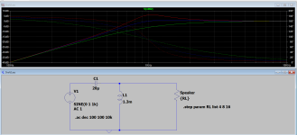
If a 16 ohm driver must be substituted by an 8 ohm driver, then the crossover components must be adjusted to suit the new impedance value.
If a 16 ohm driver must be substituted by an 8 ohm driver, then the crossover components must be adjusted to suit the new impedance value.
It's obviously complicated, as the experts are quick to point out.
Perhaps we should ask @The Ballzz for his crossover schematic. provided he has a particular configuration in mind.
My humble, corrected thought would be that in a 3-way where the midrange is band passed, an increase in tweeter crossover frequency would leave a hole in the response between the midrange output and the tweeter output.
Now, it all depends on the crossover configuration I guess, but at least this simplistic view may make some sense to our first time poster.
I will now listen intently to the experts!
I think we're all trying to get to the bottom of this.It's obviously complicated, as the experts are quick to point out.
First, please allow me to thank all for their prompt, courteous and clearly detailed replies and the warm welcome.
These cabinets are not really home stereo units, but instead semi industrial performance speakers from the now defunct "CARVIN" company! They sport two Eminence (I suspect) 15" woofer, two 4.5"- 5" mid range cones and a small 1 inch driver horn. Depending on the year, the horn driver could be Eminence, Celestion, or ????? That are set up to be able to used as a full range three-way box, or bi-amped with the two 15s for lows and the mid cones/horn for highs. While they actually sound pretty nice, the highest frequencies (8k-12K range) tend to be a bit over exaggerated, no matter which driver I try. I suspect something in the crossover network? I do believe their may be a crossover schematic still available and I'd love to share it and peruse it with you folks, if I can find it!
Thanks Again,
Gene
This is a complex schematic. I have some concerns around the way C4 is drawn in, but that's not important right now.
If I were in your position I'd pull B1 and jump a resistor across there. Some value of between a few ohms to maybe 10 or so. See if this hits the region you're concerned about since knowing this will be a way forward.
(Alternately, pulling the relay might tell you the same thing.)
If I were in your position I'd pull B1 and jump a resistor across there. Some value of between a few ohms to maybe 10 or so. See if this hits the region you're concerned about since knowing this will be a way forward.
(Alternately, pulling the relay might tell you the same thing.)
Can I assume that the relay you speak of is the box with K1 above it? And if that is the case, what actually activates/triggers that relay and what is actually accomplished by the act of it being triggered on and/or off? My untrained supposition is that it toggles a major portion of the high pass filter network on and off, along with the protection that said network may provide!
The impetus here is that I've just recently been taking out horn diaphragms at a somewhat alarming rate. At first I wrote it off to sloppy mixing/stage management skills (at pushing 70 years old), but I've been doing all this stuff (most times for a living) for a couple minutes now and am pretty good at what I do. I've very rarely blown up any gear, since I started mixing when big consoles still had rotary knobs for faders! The past few years I've spent most of my time as a guitarist/singer in a rockin' blues band and mix us from the stage.
Thanks Again,
Gene
Yes that's right. Normally the resistors are bypassed until there is too much signal.Can I assume that the relay you speak of is the box with K1 above it? And if that is the case, what actually activates/triggers that relay and what is actually accomplished by the act of it being triggered on and/or off? My untrained supposition is that it toggles a major portion of the high pass filter network on and off, along with the protection that said network may provide!
While the resistance there is probably too much to use regularly, putting a little resistance permanently in series with the tweeter may help.
From another model in the same line:what is actually accomplished
https://carvinaudio.com/pages/archive-ls1503-800w-15-inch-3-way-main-speaker
"Carvin's exclusive Speaker Guard™ HF Driver protection uses a self resetting relay circuit to dim the HF driver 10 dB protecting the voice coil from excessive power. The benefits are the driver is not turned off losing all the high frequencies, the circuit resets as soon as the high frequency content is back to normal levels."
A rather long story and chain of events. I have a gig today, so don't have time, but if you're patient, I'll share all the gory details after the weekend. I'll tease you with the ponderance that this all started after an acoustic player unplugged his direct lined guitar before I could get to the mixer to mute him! That took out a 15" woofer in one box and a tweeter diaphragm in the other!
Thanks,
Gene
Thanks,
Gene
- Home
- Loudspeakers
- Multi-Way
- Changing Horn Driver Impedance?