Attenuating high gain amplifier (Class D) for the purposes of bi-amping

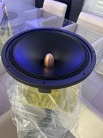
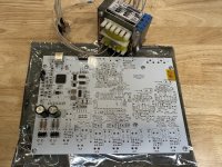
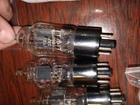
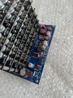
I have a 6SN7 (tubes4hifi sp14) running into pass labs Aleph J, powering, troels gravesen Faital 3WC-15 (96db) I would like to bi-amp the woofer with moderately high-power class D (I was looking at ICEpower 700AS2) there’s a couple issues and questions I’m running into

  • My preamp is single-ended, and the Ice power module is a balance differential amplifier. Can I go from RCA to XLR by connecting pins one and three of the XLR. Or do I need to use absolutely use an active device/transformer
  • The Aleph J has about 19.6DB of gain the ICEpower has 27.4DB, to get the gains to match. Can I simply add a potentiometer between the preamp and the class D amplifier to reduce gain. Or this will cause impedance issues and do I need an L pad?
    • Preamp output impedance 600 ohms
    • Aleph J input impedance 242 Kohms (RCA input)
    • ICEpower Input impedance, 36 kW Kohms(xlr )
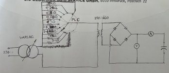
Sorry for the somewhat novice questions.

It’s a disease!

I just can’t stop building amps! Here are two KT120 SE, one KT88 SE, a EL34 SE, and a KT150 SE amp! Along with four pairs of speakers, only one of which is full factory made(Martin Logan). The others are my creations that range from a 6 inch Audio Nirvana to a Tannoy 3133 and a ScanSpeak DiApolitto Setup I built 28 years ago. I’ve got two more amps about half done, a PSE EL84 and a GU50. I can’t stop! Help me!
IMG_1102.jpeg

3" quarter wave sub

I'm making a miniature subwoofer. I contacted someone with a 3D printer, and the enclosure arrived today. I've put some glasses in the pic for comparison.

The length of the enclosure is 1.55 metres, which is exactly 1/4 of 6.2 metres.

I'm using a 3" Tang Band subwoofer, with resonant frequency 55 Hz. Sound waves with this frequency have a wavelength of 6.2 metres.

According to quarter wave theory, this enclosure should synchronise the sound waves at the woofer and the port of the enclosure, and effectively double the power of the subwoofer at 55 Hz.

There should also be some interesting 3rd harmonic boosts at 55 x 3 = 165 Hz and 55 ÷ 3 = 18.3 Hz. It will be a result if this tiny subwoofer can generate infrasonic vibrations 😊

Attachments

  • IMG_20240517_181211.jpg
    IMG_20240517_181211.jpg
    418 KB · Views: 195
  • 1715966885688.jpg
    1715966885688.jpg
    239.7 KB · Views: 187
  • 0.jpg
    0.jpg
    67.2 KB · Views: 165
  • IMG_20240519_173316.jpg
    IMG_20240519_173316.jpg
    431.9 KB · Views: 190
  • Like
Reactions: adason

Mids for mini mobile sound system

hello

long time listener first time caller

thanks for all the experience knowledge and willingness to help here

i have been putting together a mobile mini sound system, the goal of which is mobility and good sound on a budget. i strap the speakers on one hand truck and all the other equipment goes on the other. it plays reggae so i had to get an 18“ sub and a horn. it sounds great right now for dub. i am running a crown amp bridged into the sub and an old nothing amp for the highs through a 3 way mono crossover. vocals are lacking which brings me to…

i am trying to fill in the mids.

i am thinking about 2 x 8” speakers in sealed boxes, individual boxes so i can turn them outwards to spread the sound out. the smaller the better, they have to fit on the sub footprint (see pic) would like to put 100w into each. i can build boxes but would would need plans or a recommendation for a prefab. Need to buy a seperate amp for these, maybe run them bridged parallell into the speakers? total budget 3-400$

i feel like this is the meat of the system as the bass already slaps and the treble is nice and crisp from the horn. Looking for some midbass to support the 18" sub but really emphasizing warmth in the vocals.

Open to suggestions thanks in advance!

Attachments

  • Screenshot_20230616_095559_Gallery.jpg
    Screenshot_20230616_095559_Gallery.jpg
    115.6 KB · Views: 82

Capacitors specs

Could anyone help me with the specs of these capacitors, ESR, ESL, current, leakage current etc. I suspect that these are 40~50 years old and discontinued, I googled but couldn’t find nothing.

are these suitable to be used as power filtering capacitors of mosfet audio power amplifier, I know I don’t need 160V and 400V for mosfet amplifier, nor are they RIFA/KEMET PEH169 (hope I haven’t stirred up hornet’s nest)

Thank you!

P/S: I am trying to build a capacitor reformer to reform these capacitors. Drew a simple circuit and it needs a few details to be filled. Grateful for advice and perhaps a completely different circuit to share.

Attachments

  • IMG_0246.jpeg
    IMG_0246.jpeg
    364 KB · Views: 67
  • IMG_0247.jpeg
    IMG_0247.jpeg
    112.6 KB · Views: 65
  • IMG_0121.jpeg
    IMG_0121.jpeg
    62.4 KB · Views: 67
  • IMG_0196.jpeg
    IMG_0196.jpeg
    225.4 KB · Views: 61

Puxone

I wanted to hear an amplifier with current feedback, only gain 3 stages, negative second harmonic and a sound character like a single ended triode. Wanted a bit of power into 4r so I went with the pucks because of the higher power dissipation capability.
As power supplies I got some used 350w/48V meanwell smps.
I set them for 48v and the bias at 2.3a which brings the heatsinks(40x26x4cm) quite hot.
The amp can work from a single 40 to 60vdc power supply and it has a voltage gain of ~9.5x


For the moment I am using this schematic
Screenshot_17.jpg


Opto IC1 acts as a servo the keep the output of the amp at 1/2Vcc+2V.

I did some thd measurements into 4r
48v 2.3a 1w 4r.jpg


48v 2.3a 5w 4r.jpg


48v 2.3a 10w 4r.jpg


48v 2.3a 20w 4r.jpg


48v 2.3a 30w 4r.jpg


Higher output power is possible but you will need some serious heatsinking 🙂

Here it is looking shinny

amp1.jpg


amp2.jpg


There was some debugging to be done but everything was close to what the simulation shown.

Now it`s time for some tracks 😉

Attachments

  • 48v 2.3a 5w 4r.jpg
    48v 2.3a 5w 4r.jpg
    210.4 KB · Views: 70
  • 48v 2.3a 10w 4r.jpg
    48v 2.3a 10w 4r.jpg
    210.3 KB · Views: 69
  • 48v 2.3a 20w 4r.jpg
    48v 2.3a 20w 4r.jpg
    208.6 KB · Views: 60
  • 48v 2.3a 30w 4r.jpg
    48v 2.3a 30w 4r.jpg
    211.3 KB · Views: 62
  • 54v 2.3a 40w 4r.jpg
    54v 2.3a 40w 4r.jpg
    213.5 KB · Views: 69

Acoustic Elegance Issues

Well it’s back to my very helpful community … I have Acoustic Elegance woofers going in a two way horn project.

I have reached out over and over and over and just can’t get them to respond to any post sale questions.

Very frustrating.

I would say they do amazing work but will likely never buy from them again - if you can’t take 2 minutes to respond to an email (sent 4 or 5 over a TWO WEEK PERIOD now)…

Very simple question:

The gigantic rubber “gasket” with holes all the way around… how is that normally mounted?

It seems very awkward and I don’t understand how it’s supposed to look when mounted. I drilled wood screws right through… but it looks TERRIBLE.

Am I able to remove that, and use normal gasket / subwoofer mounting pieces so it has a better “finished” look?

Please see pics for where I’m at with this

Thanks in advance

Attachments

  • IMG_8868.png
    IMG_8868.png
    1.1 MB · Views: 226
  • IMG_8866.jpeg
    IMG_8866.jpeg
    316 KB · Views: 199
  • IMG_8867.jpeg
    IMG_8867.jpeg
    639.3 KB · Views: 208
  • IMG_8681.jpeg
    IMG_8681.jpeg
    353.8 KB · Views: 214

Philips CDM12 resuscitation

I've discovered the two common failure points that kill every Philips CDM12 pickup I've had in for service and I'd like to share because I know this is a hot topic for folks with these pickups and their variants (CD12 series including popular types like VAM1201, VAM1202, VAM1204 VAM1252, CD-Pro, etc.).

The first trouble I discovered is sag in the lens suspension which can be corrected by removing the lens assembly from the block, swapping the suspension arms side-side so they sit upside down, and reinstalling.

The second trouble I discovered (and this may actually help correct the first one) is the LDGU (Laser Diode Grating Unit) gets debris on its glass block where the hologram diffraction grating surface is etched. This is just normal dust buildup and smoke precipitation you get on every surface, no matter how remote, as long as it's exposed to the air. I found that on all the units I've tried so far, removing the LDGU from the optical block, cleaning the glass surface, and reinstalling, resulted in immediate restoration of perfect operation even when the unit was prior totally unable to focus (wouldn't spin the disc).

There are obvious caveats to what I mention; this is very delicate work. Thankfully these units do not require very much in the way of alignment; the lens assembly merely must be parallel with the optical block (so that its axis is perpendicular to the light path via the mirror to the LDGU) and the LDGU must be rotated to the correct orientation so that the satellite diodes receive a properly balanced tracking error signal. So far, setting the mirrors parallel and the LDGU by eye has resulted in perfect operation and it was found that manually "misadjusting" them slightly still resulted in good operation, so this design is relatively insensitive to such alignment.

I will continue to develop some procedure and take measurements of the signal outputs of a number of optical blocks in custom built test jigs so that I can show the correlation between the adjustments and the resulting output. What were primarily looking for is optimum focus and tracking error signals. Once those signals are in order, the rest will fall into place as long as there are no glaring mechanical problems, failed diodes, dirt in the optical path, weak laser, etc...

Regarding laser weakness, so far all of the units I've tested except one showed a measured laser current between 35mA and 37mA after warmup of a minute or so. One unit measured 55mA, which suggests that its laser is quite weak and the feedback diode is commanding extra current in order to maintain the desired light output level. Even this 55mA unit still reads discs perfectly, but I pulled it from use as a preventive measure and will keep it for test purposes and to help in the development of test equipment and jigs for further CDM-12 optical block investigations.

I'll share more info and pictures as this goes along. So far, I'm just happy I've brought a pile of completely dead CD players back to rock-solid operation without needing to source new pickups of questionable quality.

triode Philips TC2/250 SE amp?

I am a lucky (maybe unlucky) owner of 2 triodes philips TC2/250
is- it possible to build an SE amp of decent quality with it?
I estimate plate impedance to 4KOhm

would try to use a microwave oven transformer as a platte transformer....
what working point would you advice? plate and grid voltage?
datasheet annexed

Attachments

New project Audio Note EL84 with Audio Note M2 Pre amp

Hi,

I am spinning in my mind building a Tube Amp in a glass box. I have a glass company so the glass chassis is the least I am worried about. But on the rest I have some doubts:

The question is which transformers should I use? I have read a lot of posts on forums, there is a lot of discussion. I have some experience with several arduino projects and vintage car radios which I have retro modded with new modern technology but this field is new to me.

I am planning to build a Audio Note M2 tube Pre-Amp together with a Audio Note EL84 tube Amp

First question:
For the EL84 Main transformer I need: AC250V 350ma/6,3V 4A. Those are on the market, for the M2 Pre Amp I need: AC 300 - 0 - 300V/ AC13,8V /AC6,3V. Would it be possible to use one Main Amp for both Amps, is this possible, are they on the market and which would you recommend?

Second question:
For the Output push pull transformers it is not clear how this works, I see a huge variety of transformers on the market from 12-30 watts. What is the best to use? Can you use any of them, will the power of the Amp as big as the transformer? I can imagine the Amp is capable of handling a certain max of Watts?

Third question:
The Choke: I have read online that a choke of 20 Henry 200mA should be suitable for the Audio Note EL84. The pre amp uses a 20H 50 mA choke. Is it possible to use one choke for both Amps? I can use a 20H 300 mA version, or am I simplifying thing too much here?

Last question:
The glass box will not connect any of the grounding to the chassis, I assume using a copper rail for this application would be sufficient, agree?

The rest of the project becomes more and more concrete. I hope you'll will be helping a little bit with the above questions. Thanks in advance for your help!

dead time question

Hi there all.


I need a different deadtime arrangement for a 3 level converter.

The delay need te be different as for half bridge, I need delay for up and down flank of signal.

When I use a normal deadtime circuit I get delay on up flank also a delay on down flank,
I mean total signal is delayed. So I get a shoot through when drive signal get low. I need a
separate dealy for this low signal, I think I need a clocked design of so? with diodes I can
do some, but not as it has to be.

see the pics for clearance. The pic with the errors are the wrong one, need a double delaying
on both up and down signal to keep capacitor balance oke.

thanks in advance.

Attachments

  • ScreenHunter 2037.jpg
    ScreenHunter 2037.jpg
    51.8 KB · Views: 167
  • ScreenHunter 2038.jpg
    ScreenHunter 2038.jpg
    35.1 KB · Views: 151

Turntable Linear Power Supply

I have a Feickert turntable that utilizes a 24v Meanwell brick power supply. I would like to build a linear power supply for it. I'm searching for a kit, which I assume would be a scaled-down version of the Pass amplifer power supply, for those amp kits. A complete kit with the PC board and components would be optimal, but if I can get a PC board with a component list, I can certainly handle that after building an F5, F5T, Amp Camp, Korg Pre and a couple of other great components offered on this site. I don't see anything in the DIY Store that seems to fit this application. I would like to go a level above using the Meanwell with the filter kit in the DIY store. But may settle for that.

Any guidance or links to kits would be greatly appreciated!

For Sale Tung-Sol 6L6G

New production "large bottle" 6L6 with conservative 30 Watt plated dissipation (6L6GC equivalent).

A matched pair with less than 10 hours of use.

SOLD

Ships from Sweden

Attachments

  • 6l6g-tung-sol.jpg
    6l6g-tung-sol.jpg
    461.5 KB · Views: 104
  • 2024-03-08 17.06.20.jpg
    2024-03-08 17.06.20.jpg
    542 KB · Views: 99
  • 2024-03-08 17.06.43.jpg
    2024-03-08 17.06.43.jpg
    468.4 KB · Views: 85
  • 2024-03-08 17.07.24.jpg
    2024-03-08 17.07.24.jpg
    373.1 KB · Views: 90
  • 2024-03-08 17.07.38.jpg
    2024-03-08 17.07.38.jpg
    531.2 KB · Views: 86
  • 2024-03-08 17.08.51.jpg
    2024-03-08 17.08.51.jpg
    398.7 KB · Views: 89

EF184 in triode for phono stage input?

EF184 = 6EJ7

Since this tube has high mu as a triode, high gm, and is still pretty cheap, I'm wondering if anyone has tried it as a triode for the input tube of a phono stage? Horror stories? Successes? Noisy?

I was thinking it could be used with the plate grounded and the screen used as the 'plate' (lower input capacitance that way).

As a pentode, the Cag spec is only 0.005pF. I don't know how that translates to triode, but that's 10X less than a pentode like 6AU6A. Perhaps as a triode the Cag is down below 1pF?

PH16 phono preamp build

Hello everyone

I have had a Tubes4HiFi PH16 phono preamp kit sitting on my shelf half finished for about 2 years now and recently decided to dust it off and get it finished and operational. I just moved from my little 1 bedroom apartment to a 2500 sq ft house that I have all to myself so I have lots of room for protects now. I got my upstairs workshop started the other night and thought this would be a great little project to finish up.

Apparently I lost all the documentation that came with the kit somewhere along the way, probably during my recent move. I got in touch with Dan over at Tubes4hifi.com and he sent me a pile of amazing documentation that I'm pretty sure I never got in the first place. The instructions answered all the questions I had when I stopped working on this about 2 years ago. I'm aware the tube sockets are on the wrong side, I gotta fix that mistake.

The fancy chassis was designed with CAD software at work and then sent out to be laser cut, the top and bottom plates can be flipped around to change the orientation of the components inside. I'm currently not satisfied with how tightly the boards are squished together so I think I'm going to make an some templates and drill new holes.

When I originally designed this chassis I left lots of room inside in case I wanted to turn it into a full blown pre-amp in the future. I noticed Tubes4hifi has released the SP20 pre-amp that's based on the CAT SL1 and I might pickup one of those boards assuming it will fit inside.

I'll update this more when I'm a bit further along, I'm going to try and get some more work done this weekend.

Attachments

  • PXL_20240125_233438974.jpg
    PXL_20240125_233438974.jpg
    427.5 KB · Views: 189
  • PXL_20240125_233454636.jpg
    PXL_20240125_233454636.jpg
    484.6 KB · Views: 179
  • PXL_20240124_010216257.jpg
    PXL_20240124_010216257.jpg
    419.9 KB · Views: 172
  • PXL_20240126_000545117.jpg
    PXL_20240126_000545117.jpg
    500.2 KB · Views: 175
  • PXL_20240125_230903728.jpg
    PXL_20240125_230903728.jpg
    452.3 KB · Views: 182

Wondom/Sure BRU5

Has anyone on here bought one of these TPA3255 amps and if so what do you think of it? I have just received mine and am yet to have a listen. You do not get any leads with it and all the DC plugs to connect a PS did not fit. I worked out that the reason is the centre pin of the socket appears to be fatter than normal. I sacrificed part of a wall wart and gently drilled the centre core of the plug and made it fit.

I got mine from Aliexpress for £23 which given that it has a nice case and all the connections is silly money. Having bought a lot of different Class D boards (TA2024, TA2020, TPA3116, IRS 2092 x 2) I was keen to hear a 3255. Price has nearly doubled in only a couple of weeks


https://www.aliexpress.com/item/100...der_detail.order_detail_item.4.2351f19cUxzPuU

Heatsink drill template

Using a PCB board as a drill template for heatsink holes. The 4m screws screw into the heatsink to hold the template in place for starter drilling.
Notice that there are 4 extra holes that have been tapped 6/32 for a little extra security and also to help align parts and keep from rotating.
Each screw is inserted between the heatsink fins all the way to the flat portion and can be changed easily if it were to break on assembly.
Ignore the exposed holes seen in the flat of the heatsink, they are old positions no longer in use.
Only fitted, not assembled just yet.

1716509982420.jpg
IMG_20240523_201907.jpg
  • Like
Reactions: 6sX7

Rotel RCD 1070 - RCD 1072

Hi everyone
These days I was reading some interesting posts on Diy Audio regarding the Rotel RCD 1070 even if 20 years have passed, I'll explain the matter to you,
I still have 2 players at home
1 CD Rotel 1070 and 1 Rotel Rcd 1072, first of all I wanted to give my opinion on the 2 devices which I find fantastic but I find that... the 1072 sounds more open, better than the 1070,
the Rotel 1070 mounts the OPA 2604
the Rotel 1072 features OPA2277
now, I would like the 1070 to sound like the 1072, my question is: can I buy OPA 2277s and mount them in the 1070 RCD?
Do you think this is enough, or is there something else I could do to try to improve it to bring it closer to the sound of the 1072?

Double the output power of SET amp

Translated from Mr Ohashi's Sun Valley forum

For example, let's assume that you have a single tube amp that you like. If you are thinking in your mind, ``How much better would it be if the output was a little louder with this sound quality...” What would you do?

The simplest countermeasure, which does not require modification and is also reversible (can be restored if necessary), is to prepare another identical amplifier and make it 2 parallel single MONOs. It's a target.

Basically, by branching the input and inputting it to both the L and R channels in parallel, shorting the + side of the output transformer and taking out the output, you can transform it into a para-single with twice the theoretical output. You can. I tried to draw a conceptual diagram.


It may seem complicated when you draw it like this, but you can do it by preparing very simple attachments (branch plug and short RCA cable x 2 each).

The important point to remember is that the L and R gains of the amplifier are the same. Otherwise, it may not be possible to synthesize ideal signals. Therefore, it is desirable that the second amplifier has similar characteristics to the first. In terms of sound quality, it would be best to have the same configuration for both vacuum tubes if possible. The SV-284D balanced single is basically the same idea.

It's difficult to do right now, but I'd like to introduce an example of how two SV-91Bs or SV-S1616Ds were assembled with the same specifications at the same time, so please look forward to future reports. The SV-501SE may also be suitable.
  • Like
Reactions: CohibaJoe

I put together a simple 3-way crossover diagram and I have some doubts about it

My doubt basically about midrange speakers where I have to use a capacitor and an inductor to filter it. I would filter the subwoofer at 400hz, and I was researching on the internet and they said that I should calculate a margin so that there is no cut on top of the other, so I should make the cuts cross a little before, so that there is no peak or with value... so I should do it like this: bass cut at 400hz, the midrange will start at 450hz and end at 4khz, the tweeter will start from 4.2khz to 20khz (this is an example), is this correct or should I make the cuts precisely? 400hz - 2000hz. Also note that I inverted the polarity of the midrange, because as this filter is 6dB per octave it will generate a phase problem between the crossing of the paths (that's what I heard).
Captura de tela 2024-05-19 194801.png

Mission Cyrus Model "Pre" - Schematic needed

On this pre-amplifier device is to perform a troubleshooting procedure.
Maybe one of the member can upload the circuit diagram which is necessary due the high complexity
This thread don't provide the wanted information:
https://www.diyaudio.com/community/threads/cyrus-pre-unbalance-volume.104948/

Attachments

  • a7eeac5d-6c3f-46d9-b997-36fd689e25e6.jpg
    a7eeac5d-6c3f-46d9-b997-36fd689e25e6.jpg
    55.4 KB · Views: 85
  • f681e31d-0fb5-41c3-ad3b-3562241b5c95.jpg
    f681e31d-0fb5-41c3-ad3b-3562241b5c95.jpg
    86.7 KB · Views: 78
  • 133cc8c1-8b31-416b-bee8-3dae979d9d85.jpg
    133cc8c1-8b31-416b-bee8-3dae979d9d85.jpg
    85.3 KB · Views: 74
  • 573f4435-476a-4ac6-b975-46432c91df27.jpg
    573f4435-476a-4ac6-b975-46432c91df27.jpg
    102.1 KB · Views: 82
  • c73af2d7-6d31-4683-9d7f-483c5fa6840d.jpg
    c73af2d7-6d31-4683-9d7f-483c5fa6840d.jpg
    68.1 KB · Views: 91
  • 18e8eb27-b910-43ad-b8c9-277bc9101cfb.jpg
    18e8eb27-b910-43ad-b8c9-277bc9101cfb.jpg
    143.3 KB · Views: 98
  • 9dd09ff3-d834-4b4a-95ff-91023c0bbedc (1).jpg
    9dd09ff3-d834-4b4a-95ff-91023c0bbedc (1).jpg
    156.3 KB · Views: 94
  • mission_pre_pot.jpg
    mission_pre_pot.jpg
    75.4 KB · Views: 84
  • 9872cc27-b975-4008-9f77-aa49319daa49.jpg
    9872cc27-b975-4008-9f77-aa49319daa49.jpg
    84.5 KB · Views: 75
  • e9966322-4b14-4c5f-84d6-5025a470edf7.jpg
    e9966322-4b14-4c5f-84d6-5025a470edf7.jpg
    65.7 KB · Views: 76
  • 6f3561de-7808-4609-a568-8cce76693cd0.jpg
    6f3561de-7808-4609-a568-8cce76693cd0.jpg
    83.3 KB · Views: 85
  • eae08661-80f9-4b67-bd34-7abbd9a3b3ae.jpg
    eae08661-80f9-4b67-bd34-7abbd9a3b3ae.jpg
    77.3 KB · Views: 83
  • b43d068b-dc74-4a4d-986c-c5792d7bc0f4.jpg
    b43d068b-dc74-4a4d-986c-c5792d7bc0f4.jpg
    200.9 KB · Views: 82
  • Like
Reactions: Freedom666

Calibrate or replace? Uphoria UM3 + ATH-M50x = bass accuracy problems

I have a PC I make music on with FL Studio using a Uphoria UM3 with ATH-M50xs. As mentioned something about the EQ seems way off as when I play the music I make on various other systems (BT headphones, DSP calibrated home stereo, cars) the problem is the same- the bass sounds completely different (usually too loud on the regular stereos)

My question is, do I mess around with stuff like CamillaDSP to get the responses matched, and if so, how? If that's not feasible, what are some more accurate interface + headphone combos? I basically want to get the set up either neutral enough to translate to other systems, or matching other systems (my home stereo for example has the typical slope down from low frequencies to I forget what, I set it up years ago)

Looking for some good education

Wise people of the diyAudio Tube Forum... I'm looking for some good tube resources on the internet.

I'm an electronic tech, and well-versed in solid state, but have developed a love for the dark arts of the tube, especially in the stereo amplifier and preamp areas.

I have been looking on YouTube and found Skunkie, Tube Lab and Joy of Vinyl , awesome forums, such as this one, and some great web pages.

What other YouTube channels, or webpages would you recommend for stereo amp, preamp, and tube basics?

Thanks Dave

Is there a Neutrik Chassis mount 4pin XLR connector (female) that can have the locking mechanism removed?

Hi all,
I've bought a custom headphone amp by Radu Tarta that I'm really excited about

https://www.usaudiomart.com/details...pse-4p1l-sublime-hp-amp-and-high-gain-preamp/

And I'm trying to have him replace the 1/4" plug with a 4 pin XLR pug (still wired SE using the following wiring scheme) because all my headphones are wired with 4 pin XLR jacks so it will avoid me having to keep a pigtail dangling form the amp all the time and one less connection in the signal path.

IMG_5913.PNG


But I really hate locking connectors, and it will be especially difficult with this amp with the connector on top of the amp, I'll have to use 2 hands every time I remove a headphone from the amp. I have been told by an experienced amp builder that the locking mechanisms of these connectors can be removed.

I sent Radu these Neturik 4 pin chassis mount connectors, but he said he could not remove the locking mechanism without damaging the connector.

So I'd love recommendations on an alternative for which it is possible to disable/remove the locking mechanism. It has to fit the Neutrik screw holes because he's already got a Neutrik 1/4" plug fitted to the chassis as you can see in the pictures from the ad. And I'd ideallly like a nice connector that is gold plated like the one I linked to.

Thanks for any advice!

Or maybe someone knows how to disable the locking mechanism on the connector I linked to.

Whitney

Question regarding REW impedance measurement level difference error

Hi

So today I put together an impedance testing rig for REW. I am pretty certain that I have put it together correctly according to the schematic REW supplies, but when I try to do the open circuit calibration I get the error that can be seen in the attached screenshot.

I have everything set as can be seen on the other picture, both inputs set to the exact same 12'o clock position and the headphone output set to give me about 20dB of headroom.

A thing that is confusing me is that it says "If the input channels have individual gain controls they need to be the same.", but the measurement input is passing through an 82ohm resistor that the reference input is not, so doesn't it make complete sense the the level on the measuring input will be lower? Can anyone explain this for me?

Attachments

  • screenshot.jpg
    screenshot.jpg
    273.9 KB · Views: 98
  • setup.jpeg
    setup.jpeg
    542.9 KB · Views: 94
  • impedancesetup.jpg
    impedancesetup.jpg
    14.7 KB · Views: 108

How to calculate safe screen grid voltage when in triode mode?

I've never read anything precise about how to calculate a safe screen grid voltage for pentodes/tetrodes in triode. Can anyone help here?

Presumably it's a question of what value screen grid resistor you use, but is it more than that?

As an example I want to know what to do with the screen grid of CV9/AL60 when triode connected. Data says max Vp = 800V, G2 = 275V.

How high a voltage could be used for this in triode and what value G2 resistor?

Attachments

  • CV9 data.png
    CV9 data.png
    59.6 KB · Views: 83
  • CV9 data1.png
    CV9 data1.png
    77.3 KB · Views: 82
  • CV9 mullard x4.png
    CV9 mullard x4.png
    400.4 KB · Views: 83

Series Resistance - running the numbers in my EL84 amp

Greetings Friends. I was browsing valvewizard this morning, the Rectifiers section, and got to the bit about series resistance. I've posted about it before, don't quite get it, decided to run these equations with the little EL84 amp I built back in january.

So. As per the datasheet,
Rlim = Rsec + Rpri × (Vsec/Vpri)^2 + any extra resistance

Where:
Rpri is the DC resistance of the transformer's primary winding;
4.524 ohm

Rsec is the DC resistance of one half of the transformer's secondary winding, i.e measured from one end to centre tap;
76.55 ohm

Vpri is the primary (i.e. mains) voltage;
117 V

Vsec is one half of the secondary voltage, i.e. measured from one end to centre tap.
260 V

(260 / 117)^2 * 4.524 + 76.55 = 98.9

that's my take on it. assuming they use the same PEMDAS order of operations on the other side of the pond.

Now there's no charts on series resistance in any of the EZ81 datasheets I've found, but every sheet has a Rt value and it seems to be 2x150 Ohm for my voltage range. So I need to add 50 ohm resistance to each anode, or one between the cathode and the reservoir cap? Does the choke's resistance count?

thanks for taking a look!

w

Universal driver

I propose a mu folower driver using ECC83 and E180F tubes that can provide a gain of 100 on a load resistance formed by the power tube grid resistor of 82kohm. For an output voltage of 50v THD it is 0.3% and for 90v THD it is 1.56%. The driver can easily drive power tubes requiring a large attack like 2A3, GU50, 300b, PL504, PL509 practically all common tubes and has the advantage that there is only one stage preamplifier

Attachments

  • 300B POPA MARIUS (2).JPG
    300B POPA MARIUS (2).JPG
    147.5 KB · Views: 318

Schmitt phase inverter on small heptal pentodes such as 6Ж1П-ЕВ (6J1P-EV, 6Ż1P-EW). Is it possible and does it make sense?

When it comes to tube amplifiers, I am an amateur. I have ECL81 at low voltage and EBL21SE (which requires a few corrections due to the hum caused by the glowing lamps). My next project will be a VT52 (EL32) push-pull with toroids at the output (as in the attached photos). As I have some new Russian lamps and the ceramic stands that go with them, I'm wondering if I could use them for the Schmitt and if they would be able to rock the VT52 Mullard

Attachments

  • IMG20240511093721.jpg
    IMG20240511093721.jpg
    344.6 KB · Views: 85
  • IMG20240511095056.jpg
    IMG20240511095056.jpg
    313 KB · Views: 79
  • IMG20240511095107.jpg
    IMG20240511095107.jpg
    448.1 KB · Views: 90
  • IMG20240511095116.jpg
    IMG20240511095116.jpg
    408.9 KB · Views: 97
  • IMG20240511095218.jpg
    IMG20240511095218.jpg
    469.2 KB · Views: 108
  • IMG20240511093731.jpg
    IMG20240511093731.jpg
    308.4 KB · Views: 80
  • Like
Reactions: mondogenerator

For Sale DDDAC boards

I have a V4 main board with a stack of 11 DAC boards. These are the 2014 V3 boards (not the Tent reg version), however they have been upgraded with Nichicon FP NS series polymer electrolytics and the pin 20 resistor is a Charcroft S102J. .001%. My understanding is that they are compatible with later boards so you can have a mix of boards in your stack and still improve sound quality by adding the older boards.

I’m happy to split the stack in order to sell these but ideally I’d like to avoid selling them one by one. I acknowledge these are not as valuable as the later Tent boards and so I’m inviting sensible offers please.

Attachments

  • IMG_1139.jpeg
    IMG_1139.jpeg
    434.3 KB · Views: 190
  • IMG_1138.jpeg
    IMG_1138.jpeg
    536.1 KB · Views: 175
  • IMG_1137.jpeg
    IMG_1137.jpeg
    378.2 KB · Views: 182
  • IMG_1140.jpeg
    IMG_1140.jpeg
    562.7 KB · Views: 169
  • IMG_1141.jpeg
    IMG_1141.jpeg
    500.6 KB · Views: 178

Sealed 2-way All Dayton Build (1" and 8" Drivers)

Hello,

I am new to the community and this will be my first build. Currently using a powerful AVR and ported 5.1 speakers in my living room and I would like to upgrade the latter. I am convinced I want sealed speakers, because my sub is sealed and I like their sound better in general. So, I thought of building a 2 way 1" + 8" combination (like Kef's vintage C series). For the woofer, I chose Dayton RS225P-8A and for the tweeter, DC28FS-8. I am not sure which crossover to pick yet, but probably the Dayton two way with the frequency at 2500hz (2nd order). For this first project, I want to avoid building a crossover as much as possible.

1- What do you think of Dayton RS225P-8A's mid performance and do you think the xover at 2.5K would be enough?

2- Could you give me some idea on the enclosure design? I would really appreciate your help on this one, I am not sure which volume would be right with this woofer.

Thanks in advance.

Increasing the impedance of a 1.5 ohm sub?

Hello everyone.
I have been given a sub Sony SS-WS53 that was part of a 5.1 home cinema system.
The issue I have is that its impedance is 1.5 ohm which is quite difficult to drive, or let's say to find cheap amps for.
The lowest I found seems to be a TPA3116D2 and TPA3118D2 with an admissible 1.6 ohm and a nominal 2 ohms impedance when in PBTL.
Most of the others amps have a 4 ohms minimal load impedance.
I understand that if I put a 2.5 ohms 100W resistor in series with my sub, I would loose 2.5/4 = 62% of the power of the amp in heat. So a 100W amp becomes a 28W.
Do you have any recommendation ? (except maybe changing my sub)
Thanks

What is the word spoken here. Ten second audio clip from "Thirteen Minutes to the Moon"

I've listened to this many times and can't make out what a word is and that was spoken by Mission Control during the moon landings. This is from a BBC series of podcasts called 'Thirteen Minutes to the Moon' for anyone interested.

https://www.bbc.co.uk/sounds/brand/w13xttx2?page=1

It goes 'Eagle, Houston, we see you on the ???????? over'

What is that word?

MP3 clip:

Attachments

QCC514x chip series programming general discussion

I am trying to get an understanding of how to program the QCC5141/QCC5144 chip. I need to write code for both the application subsystem and kalimba subsystem. I will soon get a development board for QCC5141 (I don't have it yet). Would anyone with experience programming this chip like to discuss some basics? So far I don't have any hardware but I have installed all the required software (as far as I can tell). I have the ADK, ADK Toolkit and MDE 2.8. I loaded the basic_passthrough project of atil_standard_oem_earbud-ADK21.1 in MDE. I can now see a number of folders in the project pane in the left, where I believe the "loopback" folder contains the code for the Application subsystem and "download_passthrough" folder contains the code for the Kalimba DSP. There are a lot of compiler error messages in the IDE for files inside "download_passthrough" (header file not found). Could someone please explain to me what else I can do at this point now? I opened the "loopback.x2w" workspace file inside "example_apps\loopback\workspace\QCC5144-AA_DEV-BRD-R2-AA" in MDE. Why are there so many folders/subfolders in the projects pane? Am I missing any other software that can help me understand this more? Is someone more experienced willing to discuss this here?

New to audio, wanting to learn

Hi,

I am a high schooler who is very intrigued by audio design and electronic engineering, but unfortunately, I have zero (or minimal) knowledge of both topics and wanted to see if anyone here would be able to point me in the right direction to start learning. I have always loved taking apart electronics (RC cars, old electronics, etc..) but have never been able to truly grasp how to create these things, specifically, I want to create my sound systems, and frankly, I feel as though reading a book the length of a door wouldn't necessarily help; but rather lose interest - quite fast (adhd 😉 ). Any advice is great and would love to make some connections with people who are experienced in the field of diy audio. Godspeed, -Maxwell0

DC on speaker when playing bass and after a long shutdown period

Hello everyone
I received a HammerTech ECA470 with a dead power supply issue, only the mosfets on 1 bank were dead.
After I fixed the power supply section I have noticed that one channel is outputting DC on the speaker terminals only under two specific conditions, either after a long shutdown period which will output high amount of DC (probably the reason caused the power supply to die) or when it's playing bass part of the music
When the amplifier was off for couple of hours, powering it back on will caused it to output only DC with a little bit of music in bridge mode and when using each channel individualy, one is fine and the other one outputs DC only on the bass frequencies of the music.
Can you please help understand what is causing this problem?
Thanks in advance
IMG_20240516_160736-01.jpeg

Definitive Technology Mythos STS auto power on not working properly

Hi Friends,
I have a pair of mythos sts speakers, which are ok, but one of them doesn't turn on when I play some music. Those speakers have an amp in them for the bass speaker and it senses when signal is played trough my amp. I have connected the speakers trough the + / - speaker cables, since my amp doesn't have an LFE output.
If I connect the power cable of the speaker it starts, but if nothing plays for some time or it isn't very lout it powers off and doesn't turn on again. The red light on the back doesn't light up too. The other speaker is better, but also stubborn sometimes on power on and I have to plug out/in the power cable.
My knowledge is limited, but I would be happy if I manage to find the fault with your help.
I opened one of the amps and having read many stories with problems about them, I made some upgrades to the known capacitors which tend fail. That had no affect on the auto power on feature, but now when the amp starts, I don't get a loud popping sound . I changed the caps for bigger ones, following an advice from video on YouTube, about a repair of an def tech amp.
I have encircled with yellow the place on the board where the two wires giving the auto on signal connect, coming from the wire connectors of speaker cables. They are red and white and one of them goes to the big green resistor and I still haven't found where the other one goes.
20230601_100250.jpg

Here is schematic of the auto on part.
auto on.jpg
Here, as well as in the manual it states something I fail to grasp : 40-60min delay - is that turn of delay?
Your Mythos STSs contain a built-in, active powered subwoofer section as well
as an electronic crossover and must be plugged into an electrical socket of the
appropriate voltage (as indicated on the back of your unit) using the electrical cord
which you have attached to the bottom of the speaker. The Mythos STS has a
special circuit which automatically turns the powered subwoofer section on when
a signal is fed to the loudspeaker and does not require an on-off switch. Please note
that if you hear a pop from the speaker when the amp powers up, this is normal.
The LED on the back panel will light up when a signal is sensed and the amplifier
turns on. After the cessation of a signal, it may take up to an hour for the amplifier
to actually turn off. In some instances, because of stray radio signals (RF) in your
area, the LEDs may not turn off. However, this is nothing to be concerned about
as the amplifiers draw almost no power when they are idling.

What components on the board should I check so that I repair this issue. Or any hints would be appreciated 🙂

Here is a gallery with more photos of the board :

>>> google drive folder <<<

Any help would be helpfull.
Thanks in advance!
The whole pdf schematic is attached as an pdf. It is for the BP models, but from what I see, they are basically the same.

Attachments

LM1875 gets paralleled and measured for THD and power - 30/46W into 8/4 ohms

Hi all,

This has been a fun project.
Got two LM1875s paralleled and measured. Inputs are balanced.
Note the 2nd harmonics is much higher than all other. Suppose to account for a nice warm tube-like sound.
Was able to produce 30W into 8 ohms and 46W into 4 ohms.

Linear power supply using 20V secondaries (Antek AS-2220) produced 27.7V at idle. Voltage dipped under the load.

Onto the LM1875 measurements:
Gain: 25.88dB
SNR: 99.84dB
Sensitivity: 0.7mV rms

8ohm
PSU: 26.5V under the load
15.7Vrms max output
30W into 8 ohms
THD+N: 0.00825% or -81.68dB at 1kHz
THD+N: 0.00949% or -80.46dB at 10kHz
Heatsink barely got hot.

4ohm
PSU: 25.8V under the load
13.69Vrms max output
46W into 4 ohms
THD+N: 0.017% or -75.16dB at 1kHz
THD+N: 0.02% or -73.12dB at 10kHz
Heatsink got warm.

4ohm 5W output
THD+N: 0.0145% or -77.78dB at 1kHz

Benefits of using two chips in parallel include:
increase of the output drive capability of an amplifier,
reduced voltage noise (better SNR),
and reduced output offset error.

Overall the performance into 4 ohms matches datasheet graph for 8 ohms, which is to be expected.
Performance into 8 ohms is better than that in the datasheet.

Listening tests:
It is definitely HiFi sound.
If someone is on the fence, I say go for it.
With the right speakers this chip will rock.
Great resolution in mids and highs. I liked mids especially.
Hard to explain, maybe that is the signature sound of LM1875.
Lower end was not as tight. I would use separate subwoofer amp.
Overall it got pretty loud. Even with my low sensitivity ELACs.
Not as dynamic as my TDA7293 amp,
but that might have something to do with the fact that TDA7293 is three time more powerful.
Maybe higher sensitivity speakers like Klipsch will work better with this chip.
Sounded better than cheap Class D amps for sure.
Way better resolution in mids and highs.

Attachments

  • IMG_1604.jpeg
    IMG_1604.jpeg
    376.8 KB · Views: 175
  • IMG_1606.jpeg
    IMG_1606.jpeg
    317.7 KB · Views: 174
  • IMG_1605.jpeg
    IMG_1605.jpeg
    362.5 KB · Views: 161
  • IMG_1607.jpeg
    IMG_1607.jpeg
    370.6 KB · Views: 164
  • IMG_1609.jpeg
    IMG_1609.jpeg
    379.2 KB · Views: 156
  • thd_n_1khz_8ohm.PNG
    thd_n_1khz_8ohm.PNG
    26.7 KB · Views: 168
  • thd_n_10khz_8ohm.PNG
    thd_n_10khz_8ohm.PNG
    26.6 KB · Views: 144
  • thd_n_1khz_4ohm_5W.PNG
    thd_n_1khz_4ohm_5W.PNG
    26.6 KB · Views: 134
  • thd_n_1khz_4ohm.PNG
    thd_n_1khz_4ohm.PNG
    27 KB · Views: 129
  • thd_n_10khz_4ohm.PNG
    thd_n_10khz_4ohm.PNG
    26.2 KB · Views: 138
  • thd_datasheet.PNG
    thd_datasheet.PNG
    45.4 KB · Views: 171

Mid Range Selection Advice

I am working on my newest 3 way design and I am not very confident in my mid range driver selection. I was hoping to get some advice from those of you who have heard and worked with many different mid ranges.
I will start by posting my tweeter and sub selection:
Tweeter: Hivi RT1.3WE
https://www.parts-express.com/HiVi-RT1.3WE-Isodynamic-Tweeter-297-421?quantity=1

Sub: Peerless SLS 8"
https://www.parts-express.com/Peerless-830667-8-Paper-Cone-SLS-Subwoofer-264-1102?quantity=1

The mid I was thinking of using is this SB Acoustics 4" midrange
https://www.madisoundspeakerstore.c...b12mnrx2-25-04-4-midrange.-4-ohm-new-version/

It seems to fit the bill and is pretty well known. I am just unsure of how it sounds in person.

What I do not know is if I am better off spending an extra little bit of money to move to something like a SEAS or a Scanspeak 4-5" driver. Something such as one of these:
https://www.madisoundspeakerstore.c...anspeak-discovery-10f/4424g-4-midrange-4-ohm/
https://www.madisoundspeakerstore.c...ige-mca15rcy-h1262-5.5-coated-paper-midrange/

I really wish I could buy something like this but I am too much of an amatuer right now to do this driver justice I think:
https://www.madisoundspeakerstore.com/approx-5-midrange/scanspeak-15m/4531k-revelator-5.5-midrange/

All that being said, is there anything that comes to mind as a really nice bang for the buck midrange. I like a natural sound. I have heard quite a lot of mid ranges sound "synthetic". Some tinny, some dull, some muddled. A few that were really nice but I never took the time to figure out what they were.

I have a few full range drivers like my TANG W5-2143 setup in my shop pool room that has really nice tones in the mid range. It sort of gets muddied when the highs or bass hits though. Of course, this is why we all end up building multiway units in the end.

Let me know your mid range experiences. Thank you

Attachments

  • Screenshot 2024-05-21 210128.png
    Screenshot 2024-05-21 210128.png
    189.5 KB · Views: 72

Help a fool understand "ideal" or target "rp" for drive stages

Hello everyone, long time lurker with a simple question that doesn't get asked or phrased explicitly for two reasons, one being that most often the folks discussing circuits already understand the basics, and second because there are often hardware/device limitations keeping the rp value within a limited range....

So, how is the ideal or intended signal impedance to an output stage (or really between any two stages) determined? I see that often alot of effort is taken to reduce a drive stage's rp value, to a certain degree, including through very expensive means (interstage transformers). But is lower always better? How low, exactly? Are there negative consequences for dropping below a certain value, or is it just a matter of diminishing returns?

If it seems like I'm being obtuse - yes, that is the case. I've got more of an "English major" brain than an "engineering major" brain.

Let's take some specific examples? I don't know if that is necessary but.... I see some very expensive devices that will use interstage transformers to reduce a drive stage's rp from say, 3k ohm, to just 750 ohms, to drive let's say a single-ended 2a3. I see high-dollar line-stage seperates bragging about a 250 ohm output. I see that tubes like 2a3's and 300b's in a single ended arrangement seem to be more demanding in this regard, and with certain pentodes it is treated as nearly irrelevant in the circuit. So:

How is this knowledge, this number or range of values, derived from a data sheet?

Is lower always better? I.E. if it were possible to achieve let's say, 40 ohms in a way similar to OTL output stages, would there be any advantage in doing so? Would there be detriment?

Basically, how do we know that, for a 2a3, x is better than y when x=(y/2), but z is no better than x when z=(x/2)? Caveman math, I know. I can't get through any of these engineering books & I swear I'm not low iq....

My reason for asking is, in plunking around somewhat blindly with circuits, I got some "good sound" from switching driver tubes for those with lower rp while playing around on breadboard. Basically, how far should I chase that rabbit? For a single ended 2a3 or 45 or 300b (the three I really want to spend time listening to) what is about the lowest necessary? I know it's somewhere in-between 2k ohms and 250 (about the lowest from a commercial high-dollar, "cost as no object" design that I'm aware of)... Thinking about constructing a line-stage seperate to achieve crazy low rp... it's not only possible, but easy, in design, it just takes serous current for a line stage, and so, quite a massive power supply... probably twice the weight of a 300b power stage unit.... is that just silly? It's silly... right? Otherwise people would do it...? What I'm thinking about doing is the "cathode follower OTL amp" thing. There's a great tubecad page on this:

https://tubecad.com/2020/05/blog0504.htm

But half of it is over my head. But would that be a waste of time, for a drive stage? I only have so much time...

Sica 8C2CP Horn Coaxial measurements in a small enclosure.

Sica 8C2CP coaxial horn measurements. Not the greatest measurements but I couldn't find any when I looked so decided to post what I have in case it helps anyone else. I put it in a box I had that already had an 8 inch woofer cutout so the woofer is probably the least trustworthy measurement. Use the Sica published specs instead. Also, I used a B&C DE111 compression driver not a full size CD. Unfortunately, you can't remove the horn. It's glued in. I'd like to remove it and replace it with a home HiFi friendly horn. My favorite part about this coaxial is that it allows you to use any 1 inch compression driver you want. I 3D printed a bracket to attach the B&C DE111. I'd like to be able to try the B&C DH350 (1kHz crossover) on it when it becomes available. If I can figure out how to remove the plastic horn I'll print a custom horn for it.

If anyone has advice on how to cut - or press? - the horn out please let me know. Thanks.


sica8.PNG


PXL_20240519_024700869.jpgPXL_20240519_001121145 (1).jpg

Main var1 Six-pack.pngMain var1 XO-schema-1.png

0, 10, 20, 30 degree Sound Power/DI (Equalized at 20 degrees)

Main var1 Power+DI_0.pngMain var1 Power+DI_10.pngMain var1 Power+DI_20.pngMain var1 Power+DI_30.png

Normalized polars, Hor/Ver

Main var1 Directivity (hor)_Norm.pngMain var1 Directivity (ver)_Norm.png

Horn only, Woofer only

Horn only.pngWooferOnly.png


REW measurements: Horn (w/ two 33 uf capacitors in parallel), Woofer (bad results due to my enclosure)

sica8c2cpDE111.jpg
sica8c2cpWoofer.jpg

REW Horn normalized at 10 degrees.

Sica8horn.jpg

REW Horn normalized at 20 degrees.

Sica8_20.jpg

Attachments

  • Main var1 Directivity (hor).png
    Main var1 Directivity (hor).png
    37 KB · Views: 82
  • Main var1 Directivity (ver, pos front).png
    Main var1 Directivity (ver, pos front).png
    40.9 KB · Views: 100

Andy Grove designed power supply ANK L3 PSU max current

Dear all, as far as I can remember this was a Andy Grove design (AN-UK)
but I cant figure out how much current this power supply can deliver.
I am planning on feeding 2 5687 tubes with it running on 255 volt.
What I could find on the ecl 82 was 40 mA is this correct?
Please help, thanks

Attachments

  • L3PSU.jpg
    L3PSU.jpg
    59.4 KB · Views: 291
  • Like
Reactions: pompiliu

Is this going to work well? 2.5 way with dual woofers?

Hello friends,

Please can someone with more experience check is this going to work well and what result I can except:

I have 6 pcs of Faital Pro 8FE200 drivers:
https://faitalpro.com/en/products/LF_Loudspeakers/product_details/index.php?id=401030100

Also have this compression driver:

SB Audience BIANCO-34CD-PK​


Plan is to build tower speakers. Each will have compression driver from 2.4-2.5k
As a mid it will be 8FE200 with attenuation.
Dual woofers of the same type will be in 0.5 configuration.
All 3 woofers will share same box space with port.

Crossover will be 2nd order with 0.5 addition of only inductor for 2 woofers in parallel connection.
Box will be around 55 liters.

Is it too realistic to expect F3 at 40-45Hz?
Is it going to be nice speaker for hi-fi?
I have already these speakers and would like to use them in some way, don't plan to buy new speakers.

Thanks for any help!
Best regards

Bride of Zen help in operation

Hello everyone, I apologize for my translated English, I am a beginner and I have recently been playing with this preamplifier that I am building, I would like some help from you experts if possible, I made the PCB freehand and installed the components as per Nelson's manual, the preamp does its job, but how do I adjust the two trimmers? I adjusted them some time ago, but now I don't remember how I did it, maybe you can help me? I also have an oscilloscope and can display the amplitude of the output wave:


with 1khz and 3v PP in input I have 22v PP in output is this more or less correct? I used a simple unarmored 10k double potentiometer connected to the output of the rca.., Can I use a 50k Alps? or will I have problems? it's to have better volume control.


in output and without input with volume at max I have no strange hums in the woofers...


R104 and R204 heat up a lot, now they are 3w as per the manual, even Q101 and Q201 with heatsink heat up I can't keep my finger on it, R1 heats up, it's 1/2W, these components heat up but they never blew...


I inserted a LED with resistance in series, to signal switching on and off, on D4 and D2, the LED turns on when switched on but when switched off it takes a while to go off, where can I connect this LED?


I am grateful to you who help me, maybe in my small way I can also help on this forum on things that I am better at, thank you.

Simple LAN Isolator/Noise Reducer

Hello,

i just came across this device: https://www.dxengineering.com/parts/dxe-iso-plus-10/reviews on the use market and thought i buy one for 25 euro (new they seem to go for 75) to test it... result was pretty surprising imo and i wanna create my own replication of this device, so i dont have to buy more for 75 euro per piece 🙂

Screenshot from 2024-05-11 10-02-02.png


Simple dongle that i will shield "manually" afterwards with some sort of shrinkwrap/shielding/shrinkwrap "housing" 🙂
Projects by fanatics, for fanatics
Get answers and advice for everyone wanting to learn the art of audio.
Join the Community
507,714
Members
7,885,560
Messages

Filter

Forum Statistics

Threads
406,104
Messages
7,885,560
Members
507,714
Latest member
sjun1019