Hi there all.
I need a different deadtime arrangement for a 3 level converter.
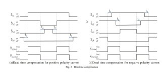
The delay need te be different as for half bridge, I need delay for up and down flank of signal.
When I use a normal deadtime circuit I get delay on up flank also a delay on down flank,
I mean total signal is delayed. So I get a shoot through when drive signal get low. I need a
separate dealy for this low signal, I think I need a clocked design of so? with diodes I can
do some, but not as it has to be.
see the pics for clearance. The pic with the errors are the wrong one, need a double delaying
on both up and down signal to keep capacitor balance oke.
thanks in advance.
I need a different deadtime arrangement for a 3 level converter.
The delay need te be different as for half bridge, I need delay for up and down flank of signal.
When I use a normal deadtime circuit I get delay on up flank also a delay on down flank,
I mean total signal is delayed. So I get a shoot through when drive signal get low. I need a
separate dealy for this low signal, I think I need a clocked design of so? with diodes I can
do some, but not as it has to be.
see the pics for clearance. The pic with the errors are the wrong one, need a double delaying
on both up and down signal to keep capacitor balance oke.
thanks in advance.
Attachments
Why don't you use the classic method with delay on switch on and fast switch off?
Something similar with this:
The image is from this: https://electronics.stackexchange.com/questions/74465/how-to-reduce-mosfet-turn-off-delay
Something similar with this:
The image is from this: https://electronics.stackexchange.com/questions/74465/how-to-reduce-mosfet-turn-off-delay

You mean a resistor and a diode?
I did try just now, it do work but make not signal of Gan mosfet better, I use the classic delay circuit
before the mosfet driver however these just delay the whole signal, so the off signal is also delayed but to the wrong direction
causing unbalance in the capacitors. Maybe I need clocked version for every separate mosfet. Read some about that.
regards
Attachments
I have a flying cap version of class d multilevel, and these have a different deadtime, mean, it need not a delay but a pauze in both
signals, this pauze is deadtime width who means then mosfets are off. this way I get not trouble with voltage error.
It is aso done with current feedback compensate the deadtime, current feedback does much better here.
regards
signals, this pauze is deadtime width who means then mosfets are off. this way I get not trouble with voltage error.
It is aso done with current feedback compensate the deadtime, current feedback does much better here.
regards
For GaN mosfets, it may be better to use separate charging and discharging (below), as opposed to using resistor-diode drive. Irrespective of topology the complementary switches are the ones that experience the dead-time. For the flying capacitor inverter, these are the outer and inner switch pairs.

The LM5113 does work like a resistor and a diode does, the resistor on one side of the driver do turn on mosfet slower and fast turnoff.
Yes, the operation is similar but the diode doesn't equal the internal MOSFET when it comes to discharging.
Proper dead-time insertion introduces volt-seconds loss. This value is Vcc*td / (2*Ts) where td, ts and Vcc are deadtime and PWM period and bus voltage respectively. You may feedforward compensate for this error if you know the direction of the load current.for flying cap i need both ends of signal delayed. otherwise i get a voltage error.
Yes, correct, But I have read here that there are solutions for that.
It is a kind of deadtime correction.
Maybe you can read and then explaine me, much thanks.
https://ynu.repo.nii.ac.jp/record/9838/files/8_AMC_Takahashi-Final2.pdf
I can also use current feedback for this because current is affected, Otherwise I stay with just
the way it is done, using feedback for correction. But learing new things is always fun.
Using gan mosfets is quite effective also.
regards
If I were you, I would use 'regular' dead-time, as already mentioned above and leave the error correction to feedback.
I'm not sure if you're doing this, but the flying capacitor voltage needs to be maintained at Vdc/2 using a closed-loop mechanism that chooses the correct redundant switching state of the inverter according to the load current polarity.
Any other 'inherent', automatic, textbook balancing would cause the flycap to gradually walk away from Vdc/2, due to non-idealities.
Hi
The inverter does have 90 degree shifted triangles and I use feedback now, I think I go that way as you mentioned.
The 90 degree fase shift take care for the Vdc/2 states. This way is stay automatically balanced.
A way is for dead time to do sense the gate drive voltages and use nor of so, only when one fet gate is zero the other get switched
and vica versa
Some gate drive ic do use this.
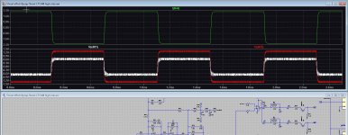
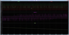
I did see when use a second order integrator the balancing and distortion is low, setting it to amplify 20 times I can insert
a postfeedback. This will be Pi controller of second order.
On second pic you see nice balance. and low distortion with quick feedback setup.
go later, when no succes, I have still fun.
The inverter does have 90 degree shifted triangles and I use feedback now, I think I go that way as you mentioned.
The 90 degree fase shift take care for the Vdc/2 states. This way is stay automatically balanced.
A way is for dead time to do sense the gate drive voltages and use nor of so, only when one fet gate is zero the other get switched
and vica versa
Some gate drive ic do use this.
I did see when use a second order integrator the balancing and distortion is low, setting it to amplify 20 times I can insert
a postfeedback. This will be Pi controller of second order.
On second pic you see nice balance. and low distortion with quick feedback setup.
go later, when no succes, I have still fun.
Attachments
No, that's the simulation only. If you need proof, try disturbing the flying capacitor from its nominal voltage and see if it 'automatically' returns to Vdc/2. I'm sure it wouldn't. This type of balancing is guaranteed to fail. It could also negatively impact the PSRR.The 90 degree fase shift take care for the Vdc/2 states. This way is stay automatically balanced.
I think that's called 'adaptive gate drive', was used by National Semiconductor few years ago.A way is for dead time to do sense the gate drive voltages and use nor of so, only when one fet gate is zero the other get switched and vica versa
Yes, that's probably the wisest way to cut distortion.I use feedback now, I think I go that way as you mentioned.
Hi
For the balancing, I can not give you a truth or lie, I follow the papers and I have to
build the thing also some day.
But loss of some friends did prevent this, I am now that far I can go start again after
let it sink.
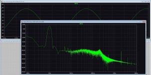
here is a pic who do with feedback from past, do well so on eye. also the square test did.
For the balancing, I can not give you a truth or lie, I follow the papers and I have to
build the thing also some day.
But loss of some friends did prevent this, I am now that far I can go start again after
let it sink.
here is a pic who do with feedback from past, do well so on eye. also the square test did.
Attachments
I did read this in a paper. With PSCPWM (fase shifted triangles) natural balancing occurs. I use this system.
Multilevel converters and flying capacitor multilevel converters in particular were presented. The paper proposed two methods for controlling the clamped capacitor voltages. The first controls the capacitor voltages by measuring them en choosing an appropriate switch state. The second makes use of the natural balancing characteristic of the converter, so the capacitor voltages are balanced without measuring the clamped capacitor voltages. This inherent self-balancing mechanism would ensure safe operation under most operating conditions. A harmonic analysis of the flying capacitor multilevel converter was developed and it was concluded that a clamped capacitor voltage unbalance is possible when the switching frequency is not much higher than the highest frequency of the reference voltage. The load impedance is of high importance and can be manipulated to enhance the effect of the natural balancing mechanism.
There are flying cap class d out there, even 5 level getting easy 2 Mhz switching. I have 1 Mhz from 500 Khz.
Last edited:
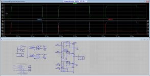
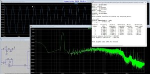
I have done some sims, one thing do I do see is strange, I get more shoot through when I set deadtime higher in
such a flying cap circuit.
Maybe this is because of the delaytimes in the mosfet driver ic?
I get with the used feedback circuit (two Pi opamps and forward feedback) nice low distortion.
And yes it is sim, trouble expected in real live, make it excited work.
such a flying cap circuit.
Maybe this is because of the delaytimes in the mosfet driver ic?
I get with the used feedback circuit (two Pi opamps and forward feedback) nice low distortion.
And yes it is sim, trouble expected in real live, make it excited work.
Attachments
I'd suggest doing three things:
1) Understand the 3-level flycap circuit and its operation completely in theory and on the simulator.
2) Get off the computer.
3) Do the test I mentioned in post #14, in case you plan to use it as a Class-D amplifier.
Note that this circuit is not just four transistors and a flying capacitor but also a lot of auxiliary circuitry that's not often shown in papers.
I do now that.
Here is also such a system who do use this. Like Merus amp where all is in the chip. Hee I am 67
so learn the stuff completely is a uge task, I do not the begin stuff and I do now the auxilary
circuits around the amp is important, like protections, but that I do now all and is of later concern
only shoot trough I do include when testing. so current can never get to high.
Do know it is hobby not professional design, I like simple, but also try to do open loop,
a multilevel is less in distortion, but have done a open loop Gan who do very good
in open loop because of the mosfet has much cleaner switching, no body diode stuff.
There are needed things for the capacitor when startup and stop, these can destroy speakers for example
so yes need to implement that for shure. Monitoring the capacitor balance is that not a feedback task?
Like we do with servo systems in current feedback analog amps? (only needed because of the temperature
sensitivity of these amps running away offset voltage.
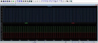
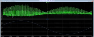
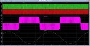
What concern capacitor voltages I do use IC=volt/2 in multisim, when I do not things are bad, that is what
you did warn about. See pics, left is unbalanced and left balanced. Did balance in ltspice with IC=80 on flying
capacitor so sim start balanced.
Here is also such a system who do use this. Like Merus amp where all is in the chip. Hee I am 67
so learn the stuff completely is a uge task, I do not the begin stuff and I do now the auxilary
circuits around the amp is important, like protections, but that I do now all and is of later concern
only shoot trough I do include when testing. so current can never get to high.
Do know it is hobby not professional design, I like simple, but also try to do open loop,
a multilevel is less in distortion, but have done a open loop Gan who do very good
in open loop because of the mosfet has much cleaner switching, no body diode stuff.
There are needed things for the capacitor when startup and stop, these can destroy speakers for example
so yes need to implement that for shure. Monitoring the capacitor balance is that not a feedback task?
Like we do with servo systems in current feedback analog amps? (only needed because of the temperature
sensitivity of these amps running away offset voltage.
What concern capacitor voltages I do use IC=volt/2 in multisim, when I do not things are bad, that is what
you did warn about. See pics, left is unbalanced and left balanced. Did balance in ltspice with IC=80 on flying
capacitor so sim start balanced.
Attachments
Last edited:
Well I'm glad you understand the auxiliary requirements. Yes, a wrong initial voltage of the capacitor would correctly demonstrate what I meant above.
Monitoring capacitor is feedback but this is independent of the audio output feedback of the amplifier. The capacitor voltage is picked up by a sensor to obtain the charge /discharge status that in turn applies the correct Vdc/2 state according to the load current polarity (also picked up using a sensor). All this happens once every switching cycle.
Further, you'd also need a slow turn-on of Vdc to ensure that the capacitor gets sufficient time to track the half of the supply voltage.
To get multilevel PWM benefits without breaking your head, please read Karsten Neilsen's paper on Parallel PSCPWM (attached). The circuits are much simpler than what you're currently attempting.
Attachments
- Home
- Amplifiers
- Power Supplies
- dead time question