I've never read anything precise about how to calculate a safe screen grid voltage for pentodes/tetrodes in triode. Can anyone help here?
Presumably it's a question of what value screen grid resistor you use, but is it more than that?
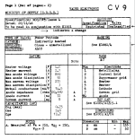
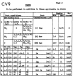
As an example I want to know what to do with the screen grid of CV9/AL60 when triode connected. Data says max Vp = 800V, G2 = 275V.
How high a voltage could be used for this in triode and what value G2 resistor?
Presumably it's a question of what value screen grid resistor you use, but is it more than that?
As an example I want to know what to do with the screen grid of CV9/AL60 when triode connected. Data says max Vp = 800V, G2 = 275V.
How high a voltage could be used for this in triode and what value G2 resistor?
Attachments
How much the g2 current at -for example- 275V?
If it's xmA, then the resistor value is
R= (Ua-Ug2)/x
-considering the max power of g2-.
BTW in case of old tubes the exact g2 current never as much as in datasheet, so the practice decides the correct resistor value.
p.s. if the Ua below the Ug2 limit, I would use -for example- 100...470R resistor for g2 to anode.
Last edited:
In a triode connected pentode g2 swings together with the anode. I think this is the reason of lower voltage spec, because the peak might go to double of the idle voltage on both electrodes. It is not about dissipation, rather internal electrode spacing. For comparison, here is the data sheet of the 807, where the max. Vp is 400 Vdc.
https://frank.pocnet.net/sheets/084/8/807.pdf
https://frank.pocnet.net/sheets/084/8/807.pdf
Hello Bela - thanks for replying. I would want to run the CV9s at between 50mA and 60mA. Say 55mA as a ballpark. The valve is rated at 18W dissipation so to reach that you would need....
360V a-k at 50mA
328V a-k at 55mA
300V a-k at 60mA
So wondering how high I can go here, since some of my SE OPTs are rated at 50mA nominal.
R= (Ua-Ug2)/x
So for example if Ua-Ug2 is 50V and x is 0.05A, you would use a 1K resistor?
360V a-k at 50mA
328V a-k at 55mA
300V a-k at 60mA
So wondering how high I can go here, since some of my SE OPTs are rated at 50mA nominal.
R= (Ua-Ug2)/x
So for example if Ua-Ug2 is 50V and x is 0.05A, you would use a 1K resistor?
Last edited:
If the Ig2 max -for example- is 8mA (practically always lower), and total allowed current of OPT is 50mA, the approximate anode current is 42mA.
So if you biasing tube to 360V (if it good for OPT loadline), 42mA operating point, the tube within the dissipation limit.
If the overall (Ia+Ig2) current is lower than OPT max. current, can be increasing Ia (Ig2 also increasing) -with bias changing-, till the limit.
BTW AL60 isn't similar (other socket), than EL12 or EL36?
The g2 follows the plate, although often with a screen-stopper. This is how triode connected tetrode/pentodes work.I've never read anything precise about how to calculate a safe screen grid voltage for pentodes/tetrodes in triode. Can anyone help here?
Presumably it's a question of what value screen grid resistor you use, but is it more than that?
As an example I want to know what to do with the screen grid of CV9/AL60 when triode connected. Data says max Vp = 800V, G2 = 275V.
How high a voltage could be used for this in triode and what value G2 resistor?
Any limitations on the screen voltage will push the tube closer to pentode mode ( which by itself is not a bad thing)
If this is not acceptable you should use another tube ( KT88 is one suggestion, EL34 another). Forcing a tube way outside it's
limits is often bad.
This article is a very good place to startI've never read anything precise about how to calculate a safe screen grid voltage for pentodes/tetrodes in triode. Can anyone help here?
http://www.audiodesignguide.com/New2A3/ETF06TS.pdf
Edit: wanting precise and safe is asking the impossible when charting unknown terriorty, but careful experimentation with the help of a variac taking care to stay within the specified G2 limits in the datasheet and using a valve which others have successfully tried is about as close as your going to get to a low risk venture. As I recall George (Tubelab) has reported in the past about testing tubes in such a way to destruction which came soon or after a somewhat limited life. The internal construction will make a difference and that's rather hard to measure without smashing the tube and doing far to much maths.
Last edited:
Yes, it's an old B7 socket. A very rare valve, I just happen to have some. Not worth bothering about in general. I don't use EL36, but I used to use EL38.BTW AL60 isn't similar (other socket), than EL12 or EL36?
EL12n isn't a problem at higher g2 voltages and neither is EL12Spez both of which I use. Some EL12 like TFK are OK, but others like Valvo seem to have a 250V g2 max. EL12n is available new and cheap from BTB and others. Not interested in EL34 types, not enough gain. EL12n is mu of 18 so can be used in a 2-stage SE amp with lower mu drivers which I prefer.
So still trying to get my head around the calculations - keep the posts coming! Very helpful.
You simply obey the screen voltage and following the current rating of your output transformer and the rest will fall into place, even at the expense of lower plate dissipation than desired. High screen voltage is often the cause of shortened tube life, especially in UL designs pushing for high power. Go conservative here.

- Home
- Amplifiers
- Tubes / Valves
- How to calculate safe screen grid voltage when in triode mode?