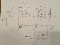
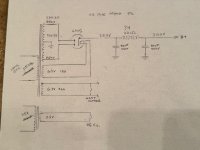
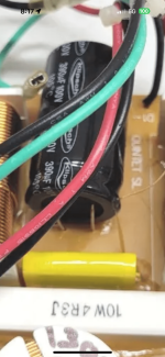
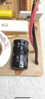
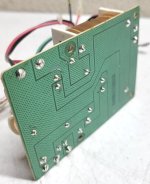
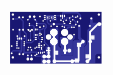
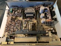
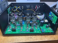
NAD 1600 Re-Cap

Hi All,

1st time poster!

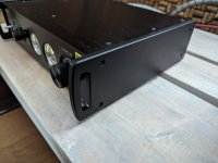
I'm running an old NAD 1600 and 2 NAD 2600's...sometimes bridged sometimes not.
I replaced the speaker relays in both 2600's a few months ago and now they work great!
The 1600 has now started to have the left channel louder than the right. I have confirmed this buy running each 2600 separately with a different pre-amp.

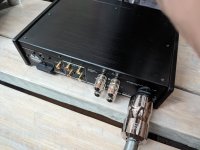
I haven't opened it up yet to take a look but am wondering, could it be something as simple as bad solder joints on the pre-in rca connectors?
or is it just time for a re-cap?

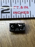
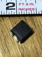
Any suggestions of caps if thats the case? I did find this kit from the UK
https://www.audio-high-store.com/product/nad-1600-upgrade-kit-audio-capacitors/

Any suggestions are greatly appreciated!
Foo

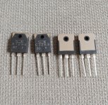
For Sale Sanken 2SA1294 & 2SC3263

I have 100+ pairs of these (NOS).

20240812_111523~2.jpg

SOLD!!

I guarantee that these are genuine Sanken. Feel free to test them any way you like (or even crack them open to check the insides). If they turn out not to be genuine or if you have any doubts about their authenticity, you can send them back to me (I’ll cover all the return costs), and you’ll get a full refund.
You can mention this in PayPal when making the purchase.

PM me if interested.

Thanks for looking!

Nakamichi BX300E has a squealing sound?

I have a Nakamichi BX300E on the workshop table, and after completing the service I discovered a faint howling/squealing sound from the drive. The frequency of the sound changes up and down when the pitch knob is turned. The sound seems to be produced by something mechanical - perhaps the flywheel? Has anyone observed a similar phenomenon? And what was the reason?

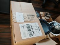
For Sale Troels Gravesen Faital 3WC-10 all drivers

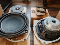
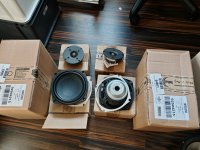
I have for sale a full set of drivers to build the famous Troels Gravesen Faital 3WC-10 3-way speaker pair.
I bought 2 sets and have another for sale because I only finished one set and don't need the other one. I planned to make a WMTMW version of this but the Gravesen original version is already good enough. I'm very happy with the sound of this speaker.

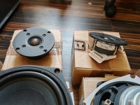
The following drivers are included:
-2x Scan-Speak D2608/913000 = Peerless HDS DT26/08 https://www.lautsprecherkauf.com/SCANSPEAK-D2608-913000.html
-> These are used, barely broken in. Terminals are soldered.
-2x Faital Pro 6RS140-8 http://www.troelsgravesen.dk/Faital-3WC-10/6RS140-8.pdf
-> These are used in test cabinets but not even broken in
-2x Faital Pro 10RS350 http://www.troelsgravesen.dk/Faital-3WC-10/10RS350.pdf
-> These are new in box, never used, in an unopened sealed box.

Jantzen Audio sells this set of drivers for 600 EUR without taxes, means around 750€ with local taxes + shipping.

I'm asking 500 EUR for the set.
Shipping cost will be added. I have the original boxes and can ship to almost anywhere. Ask for shipping quote to your location.

More info here: http://www.troelsgravesen.dk/Faital-3WC-10.htm Here is a summary of that page:
"Dynamic and with a degree of 3-dimensionality rivaling whatever speaker I have ever made, regardless of brand and costs. I know this is big words, but I'll stick my neck out for any comparison on transparency and 3-dimensionality"
"Of any mid-sized 3-way classic, this is the best I've made."

Attached are the photos of the actual drivers.

If you wish, I can measure the drivers using DATS v3 as a proof that they are working as they should.

Attachments

  • IMG_20240901_175052.jpg
    IMG_20240901_175052.jpg
    529 KB · Views: 142
  • IMG_20240901_175103.jpg
    IMG_20240901_175103.jpg
    307.3 KB · Views: 121
  • IMG_20240901_175109.jpg
    IMG_20240901_175109.jpg
    458.1 KB · Views: 122
  • IMG_20240901_175114.jpg
    IMG_20240901_175114.jpg
    414.8 KB · Views: 113
  • IMG_20240901_175123.jpg
    IMG_20240901_175123.jpg
    323.2 KB · Views: 120

FreeDSP AURORA, Jab5, ADAU1452, ADAU1701 - Mess

Hello guys,

I have recently been playing around with a Wondom JAB5 (adau1701 based dsp with 4x"100W" amplifier). This jurney have made me fall deeply in love with sigma studio. It makes working with my fusion amps feel like a joke.. really wished hypex would let us talk to and program the Adau1450 directly.. maan that would be awesome...

However, the Jab5 board and as far as the WWW tells me all other Wondom products have a rediciulesly high noise floor. I have used it to build a pair of pc speakers, and even at moderate listening levels the noise is still audible.
I really really wished there was a decent quality product for maybe double the price that just had the DSP and 8 outputs ready to be connected to amps, but i cant seem to find any.
The best i could find was the Ali/ebay baords discussed in this thread:
https://www.diyaudio.com/community/threads/low-cost-adau1452-china-board.309680/page-24#post-7781475
But having read that thread from start to end, i dont feel thats worth the hassel, simply to bad quality products...
Im leaning more and more towards the official AD eval board:
https://www.digikey.dk/da/products/detail/analog-devices-inc/EVAL-ADAU1452REVBZ/9809249
But the price of that board is almost the same as a full Fusion amp...

Is there really nothing in between china trash and top of the line AD board?

FreeDSP Aurora cauhgt my eye. However, i have no experience in pcb manufacturing via PCB-way and so on so it seems like a daunting process, and i have no clue what the final cost would be...

Has anyone here built the Aurora DSP within the last couple of years?
Is it still worth the effort?
Is it cheaper or more expensive than the AD eval board?
Can it be partially build to only have the DSP functionality without the usb stuff to save cost?

Really hoping for some feedback from someon with FreeDSP experience... Thanks in advance!!

TDA1541A test board issue - DEM oscillator not working

So I built a test board to try and measure some ideas. I added the components for the famous Grundig DEM clocking and it was working fine. Then I though I check it against the data sheet single capacitor solution, I connected a 680 pF foil capacitor between pin 16 and 17. It does not work. There is some low level, high frequency oscillation, but definitely not the well known waveform that should be there. I checked the capacitor, potential solder bridges, continuity, everything looks in order. What did I miss? The chip is in a socket.

GerardV?

Maybe I'm just stupid, but I can't figure out how to "contact GerardV", as directed in the Member Blog area. There's no "start a discussion" option below his information box to contact him by. ??

I'm thinking about starting a blog, about a DIY project that others might be interested in, but if I can't do a blog then it might just have to be a forum thread.

Thanks
Bill

Audiosource Amp 310

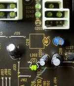
I've had an audiosource amp 310 faithfully serving me for over 9 years. It recently started behaving erratically, and now takes 20 or 30 minutes to eventually come on after being powered up. When but when it does come on, the amp functions just fine. The behavior is consistent regardless of the auto-on settings on the amp. There is no evidence of burnt components or leaking capacitors, so I am guessing there is a bad relay somewhere inside.

I have reached out to audiosource and googled high and low to find any information on this amplifier. There are several posts in this forum related to the amp 200/300 but from looking at the drawings, they are very different from the 210/310.

If anyone has any documentation on the 210/310 or advice generally, I would appreciate you sharing it.

Many thanks!
Brandon

B2 AUDIO M15R the raven! Output Mosfets

Hi guys, a B2 AUDIO M15R amplifier with a burned audio section is about to arrive at my lab.

Looking at the board online, it seems to be a classic Korean one with 1 X IR2184 + 2 X TC4452 buffer and if memory serves, it should use FDA20N50 as output mosfet.

If so, I saw that the output mosfet is not very easy to find at the moment.

Has anyone tried any reliable substitutes?
Did you have to make any changes?
thank you all

Dead KEF X300A - what to do with them?

Hey there,

Kind of off-topic, but I need your opinion. I've got a pair of KEF X300A that aren't working any more. Apparently there is an issue with the power board. According to some comments on the internet, it's an expensive replacement that's probably not worth it.

I'm now wondering what I could do with them, I'm neither an audio nor electronics nerd (besides basic stuff). Does it make sense/is it possible to use them as passive speakers somehow?

I'm thinking about replacing them and wonder with what. I've used them as Desktop speakers, the sound is excellent. But I'm not sure if I want to use active speakers any more, don't want to throw them away again if they break.

Anyone got an idea?
Thanks a lot!

Installing the new 2023 version of LTspice

********** Installing the new 2023 version of LTspice **********
This is a companion thread to:

Installing and using LTspice IV (now including LTXVII). From beginner to advanced.

********************************************************************************************************************

LTspice 17.1 is a significant upgrade to LTspice XVII, including new features and numerous performance and stability enhancements:
  • Transient Frequency Domain Analysis. LTspice 17.1 includes a new frequency response analyzer component and associate .fra spice directive.
  • Frequency domain analysis has been reduced to a single component and directive, greatly simplifying the generation of Bode plots for non-linear circuits, including switched mode power supplies
  • Both loop gain and output impedance are supported by this feature
  • Improved Installation. LTspice library files are stored in users’ %LOCALAPPDATA% directories, instead of My Documents
  • Waveform Viewer. Faster plotting speed for large datasets
  • Keyboard Shortcuts. Keyboard shortcuts can be saved to and loaded from text files
  • Schematic Capture. Numerous schematic editor bugs have been eradicated
  • Simulator Operation
  • Fixed a number of convergence problems
  • Updated initial conditions behavior and documentation to match behavior
  • Reduced multi-threaded CPU loading

We, the LTspice development team we are very interested over your feedback.


***********************************************************************************************************************

This thread is very much a work in progress and is not intended to be a definitive tutorial.

Take away points at a glance:

The locations and file paths of the directories used by LT are as follows:

%userprofile%\AppData\Local\LTspice
(this is user profile location of the 'examples' and 'lib' folders that in LTXVII were located in 'Documents')

%userprofile%\AppData\Local\Programs\ADI\LTspice
(this is the location of the program files that in LTXVII were located in C:\ program files)

%userprofile%\AppData\Local\Temp
(this is a temp folder. Running a .asc from a file located in the above link (program files) will create a zipped temp folder for that particular sim )

The latest incarnation of LTspice brings some fundamental changes to the way LT is installed and used. The big difference is in the locations used to store the program files and in its handling of temporary files.

If you are installing alongside an existing installation then only certain sections of what follows will be applicable.

Also note that Analog Devices have said that the new version coexists happily with the older version. I made the personal decision to move exclusively to the latest version because I felt that two systems that are fundamentally different in their operation and in their handling of files was going to be problematic although YMMV on that viewpoint.

Having decided to make the switch now to exclusively use the latest version I devised this procedure. What follows relates to Windows and was devised to give a clean install of the latest version.

Warning... make sure to back up ALL of your personal LT files and models wherever they may be located. If you have any residing in the protected program files area then back these up BEFORE uninstalling LTXVII

1/ Download the new version of LT direct from the analog.com site. Do not install at this point.

https://www.analog.com/en/design-center/design-tools-and-calculators/ltspice-simulator.html

2/ Uninstall the existing installation of LTXVII via Windows 'Control Panel' by going to 'Programs and Features' and clicking on LTXVII. Follow the on screen instructions. Also
delete or unpin any shortcuts you may have on the taskbar, start menu and desktop. The program deletion will not affect any of the existing LT files in your user Documents Folder. This includes the 'Example' and Lib' folders.

01_Uninstall.jpg


3/ Manually delete the 'Examples' folder from the Documents location of LTXVII

4/ Manually delete the 'Lib' folder from the Documents location of LTXVII but first check you have copies of all your own models you may have created.

5/ Copy the LTXVII folder in Documents to a secure location if needed for future reference. In my case this contains all my own LT files of information, sims etc.

6/ Delete the LTXVII folder in Documents and restart the PC. Remember to make sure you have backups of personal files located here.

7/ Warning. Do this next procedure at your own risk. Modifying the registry can cause system instability if done incorrectly. What I am doing here is deleting all references of LTXVII that have been left behind following the uninstall.

Open 'Regedit' and click 'Edit' and 'Find'. Delete all entries relating to 'LTspice'. Use 'Find Next' to work through the registry. When completed restart the PC. A further check should now reveal no instances of LT remaining.

02_RegEdit1.jpg


03_RegEdit3.jpg


03_RegEdit2.jpg


8/ You can now run the installer for the new version in the normal way. Accept the license agreement and follow the wizard. Installation is very rapid compared to the older version and took under 10 seconds.

9/ You will now have a new desktop icon for LTspice. Hover over the icon and note the file path. I would recommend you create a text file and paste all these file paths to
that as a means of keeping a record of what is where. This is very important because the installation is now in a non indexed location which is a major plus point for
anyone who uses disk imaging. This is because the Windows index file is not normally included in a disk image and it can take a long long time to rebuild following a
restore. Before I started this I had around 38k indexed items. This figure is now around 25k with most of those 'missing' entries being the tiny model files included with LT.

04_Filepath1.jpg


10/ The first thing I noticed opening the new version is that the new version doesn't scale correctly and the text on the top toolbars is not as sharp as it should be.
That may be because of custom setting I use within Windows. To correct this close LTspice and then right click the desktop icon and click 'Show More Options' and
select 'Properties'. Copy the file target file path which for me is:

C:\Users\karls\AppData\Local\Programs\ADI\LTspice\LTspice.exe

and enter that file path in Windows search box to open the location.

Right click the search result and select 'open file location'.

Alter the High DPI setting as shown.

05_DPI.jpg


11/ Reopen LTspice and the text should now be pin sharp. If Windows opens a box asking Did this program work correctly' answer as appropriate. Hopefully a yes.
I would suggest you now familiarise yourself with the main differences in how LT operates and works with files and folders. Remember that target file path from
earlier. If you look at that but this time delete the end part of LTspice.exe you will open the location of the files if you paste it into the Windows search box.

You should see the familiar 'Example' and 'Lib' folders are now located here (see above image). Notice they are now zipped (compressed) folders by default.

13/ At this point I think it useful to create a shortcut to open the location where LT now resides. I placed two Icon Files (.ico) that I created earlier in the new location that LT resides in and
created a shortcut using these icons. One is for the Program Files and one for Temp Files which we will cover later (Step 13 below).

To add the .ico image. Right click the shortcut and select 'Properties' and the 'Change Icon' tab. You need the file path of the icon to paste into the location box.
If the icon symbol does not display when applied to the shortcut then just 'refresh' the desktop.

06_Icons.jpg


The program file shortcut should open to this.

07_Program Files.jpg


12/ I recommend you now run an example such as the 'Audio Amp' found in the new Examples folder. If you are running alongside an existing installation be sure to use the
new folder.

Run the simulation in the normal way and then close LT.

13/ We will now look at a major difference in the new version. Open LT again and click 'Control Panel' (the hammer symbol on the toolbar). Click the 'Operation' tab and
note the filepath for temp files. This is my file path.

C:\Users\karls\AppData\Local\Temp

I would recommend you copy and paste that file path into a new shortcut which will give you easy access to this location.

Close LT again.

14/ Navigate to this new Temp File location and you should see a Zipped folder that was created when you ran the example above. It remains there until you delete it. Each temp
folder contains the three temporary files we are familiar with in the old version.

Run another simulation and another zipped folder is created. So by leaving LT at its default settings we find we have a new zipped folder that is created for each occasion that a simulation is run.
This is something to be aware of this as the space these take up will increase over time.

Keeping tabs on all these is why I recommend creating those two shortcuts to give you easy and instant access to the file locations.
08_Temp Files.jpg

AK4499 DAC Design

Hello,
I wanted to design an open source and open hardware DAC around the AK4499 DAC Chip that other members are free to copy, reuse, share, and remix. I previously started a thread for doing this around the ES9038, which piqued my interest at first, but have found that the restrictions that ESS places on their documents go against the values of this project. I am moving forward with the AK4499 As the DAC chip, either using another AK chip or the WM8805. Planning on using either an Op-amp or JFET based I-V stage, and separate LDO's for each of the power supplies on the chip. Unfortunately haven't seen the Eval Board schematics, would appreciate if somebody could post them.

Elektor-Giant 1000W

Hello!

I hope someone of you can help me with the following problem:

Does anyone rember to the giant 1000 from elektor?

I have biult this amp but it makes some trouble.
First of all i had to replace the original 2SK135/2SJ50 to the 2SK1058/2SJ162. Then i had to biult up a new PCB to fit the schematic on a 100x300mm card. The new layout is very similar to the original from elektor except that i mounted all MOSFETS and the voltage regulators on the same heatsink. Next i built the security schematic from the giant 2000 also from elektor, because its better then that one for the giant 1000. After that i tested the amp. Everthing works fine till the relay in the outputline conected the speaker to the amp. I hear a little hum and when i switch the amp off the relay falls after 5ms. In this time period, a very nasty and loud noise comes from the speaker.
Does anyoune built up this amp and made the same experience with it in the power-off sequence?

thx

PS: if you need more information, please ask.

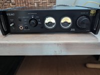
For Sale Teac AI-503

Selling my Teac AI-503. This was used in my second set for a couple of years without any issues.
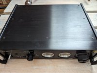
There are few minor scratches on the top lid, can be seen in the photos. Also, one meter backlight lamp has been replaced, so the backlight color is slightly different on the other side, also can be seen on the photos.
Price 300€ 230€, can be shipped almost anywhere. I do have the original package.

Attachments

  • PXL_20240616_070634547.jpg
    PXL_20240616_070634547.jpg
    350.2 KB · Views: 129
  • PXL_20240616_070639951.jpg
    PXL_20240616_070639951.jpg
    375.1 KB · Views: 148
  • PXL_20240616_070610834.jpg
    PXL_20240616_070610834.jpg
    306 KB · Views: 150
  • PXL_20240616_070701906.jpg
    PXL_20240616_070701906.jpg
    345.2 KB · Views: 137
  • PXL_20240616_070620565.jpg
    PXL_20240616_070620565.jpg
    368.9 KB · Views: 112
  • PXL_20240616_070628141.jpg
    PXL_20240616_070628141.jpg
    303.8 KB · Views: 106
  • Like
Reactions: Gaspar74

CLD based segmented turntable platform

Let me share an idea I had some days ago that's spinning round my head.
As I was experimenting with a few material combinations in order to build a CLD based platform for my DIY TT I came up with the following: Why not have a segmented design?

It may look like this:
1725282763017.png

My idea behind that was, that the feet of the TT as well as the motor unit will stand on separate segments. So for example the vibration propagation from one foot to the other would be less than with a standard platform where all feet and the motor unit would stand on the same plate.

Let me hear your thoughts on this.

Cheers
Stephan
  • Like
Reactions: tmuikku

Pros & Cons of different stacking of Subwoofers

I will give specific details on the project I am working on but this should apply to most others too if one adjusts accordingly.

In the example project, we will utilize B&C S218BP subwoofer enclosures with 18DS115 drivers. In the end we aim to have 12 of these enclosures. They will be crossed around 60-80hz to our midbass enclosures (they can play down to 60hz in stacks and each contain 2x15" B&C drivers). On top of the midbass we have tops.

I will calculate the mutual coupling distance from 80hz as they will still be making a lot of spl around there even when crossed at 60hz. 80hz has a wavelength of about 4.29 meters. 1/4 of it is about 1.07 meters. So, theoretically mutual coupling within working passband is possible within 1m distance.
Adhering to that, there would still be many ways to stack these. What would be the pros and cons for these different scenarios?

*Please, let's assume open-air, so no room gain etc. to effect our preference.

Here are the three different scenarios.
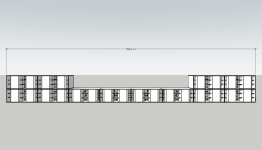
Scenario 1
bassarray1.jpg

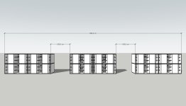
Scenario 2
bassarray2.jpg

Scenario 3
bassarray3.jpg

Breaking more than I fix

Hi. I've just arrived here trying to find some info on a stereo I'm trying to "fix". I need some info on the Creative SoundWorks 740. I am trying to modify it so that I can retain the clock and throw away most of the rest of it. Bit of a silly idea, but that is where I have got up to!

If anyone has any info on the LCD circiut board on this, I'd appreciate it.

Regards

Lawrence

Creative SoundWorks 740 Information

Hi

I have a Creative SoundWorks 740 that I am trying to modify rather than throwing away, and I could do with some guidance!

I want to keep the front panel (because I like the clock) a throw away the rest. I need to power the front panel independantly. Does anyone have any idea of the voltage required and where to apply it? It looks like there are some 74 series chips on the board which (I think) implies a 5v circuit but wondered if anyone had any ideas

Taking it a step further, getting the radio working again would be a bonus - though I would need to add an amp of course.

Thanks

Lawrence

Hello all!

Hey all, just introducing myself here. I'm a product designer living in San Francisco. I began tinkering with electronics a couple of years ago. My experience so far has been centered on vintage gear. I have restored three Sansui Au-717's, Marantz Sixteen, Marantz 2020 and a Yamaha 1020. I have also built an Elekit Pre amp. I'm interested in learning more and taking on a new challenge, my next project will be an amplifier build of the Honeybadger. Thank you for sharing all of your knowledge and supporting us newb's!
I'm looking forward to attending Burning Amp this year and maybe meeting some of you in person!

Hi there from Finland

Hi from a Kiwi based here in Southern Finland, getting back into electronics as I get closer to retirement. Was once a Radio Tech with a keen interest in all things audio. Things have changed a lot since I was on the bench but picking up new skills, equipment and techniques. If only my eyes were as good as they once were! Microscope is on the shopping list for sure! Here's the messy workshop in its current state of disrepair, Disembowelled Anthem on the bench as I trace an Amp protection fault without a schematic, Anthem just wont give 'em out, So need to do it the hard way!

Have found some valuable hints in this forum so thought it was about time I joined up. Who knew that the Pioneer A-400X DC protection cct could be found lurking in this Anthem!

IMG_0363.jpg

Akabak Impedance Graph

Hello 🙂

I simulated a closed Box design in Akabak and i also built it. My Impedance Graph in Akabak looks odd to me. Here yo u can see the LEM Page, with all the Parameters for the Driver.

1716534867118.png


The Values are all correct. Driver is B&C8BG51.

Here is the Impedance Graph, calculated by Akabak.

1716535034733.png


The Resonance frequenzy around 90Hz is fine but towards the higher Frequencies id expect a rise in Impedance. And that is what i measured in REW aswell.

mDS6W7AwM9n4lXn7EhM8XlzvR3C16cqPs6zvFgTVpP86ikngtU7OivWMIiH7WXiwNvid5_c4LpwQyO3miVa6QjRQfItSKtnLB7D82b78C1GjRH3muc0OAyUKD_TTo3zDLFSEQ2lxUTG82hGt9RjoCoc


I should add, since this could be the Problem. The only Impedance i can measure in Akabak is the Source Impedance. I assume it is the Impedance "seen" by the source but i may be wrong.

kind regards and a nice weekend

Elias

Using a notch filter to assess soundcard ADC and DAC side harmonic distortions

My situation is that I have a venerable EMU-0404 USB soundcard which appears to offer quite low levels of harmonic distortion for loopback tests, but I could not confirm whether the DAC/headphone output signal was the primary contributor to HD levels, or whether the ADC/input was a substantial contributor. So far it has not been a concern to how I use the soundcard for bench-top measurements, as the inherent soundcard HD levels are well below any DUT scenario I have had. However, interest to assess this topic has increased over the last year or two as my go-to software REW now has enhanced features to assess low HD levels due to coherent averaging, and the ability to add in trace levels of harmonic distortion in its tone generator. The selective addition of harmonics can effectively null HD levels down in to the noise floor for a specific sinewave frequency and hence provide a high performance poor-man's oscillator that seemingly approaches the likes of what some have built on this forum.

I don't have an AP style system to investigate this topic, so am running the gauntlet by using just the DUT soundcard itself and a diy passive resistor-divider attenuator, and a passive twin-T notch filter.

With a plain loopback setup, a 1kHz tone with headphone level pot at max can generate a low distortion signal of up to 2.46Vrms (using a software setting up to 943mVrms of a 1V FS level). That 2.46Vrms level does not overload the ADC/input when the input pot is at min, and adjustment of added harmonic levels can suppress loopback harmonic levels to <-130dBr for H2 and <-140dBr for H3.

With a passive -20dB resistor divider attenuator included in the loopback, and with no added harmonics to the 1kHz sinewave, the default 2H level of -115dBr is reduced to -122dBr, and the default 3H level of -103dBr is about the same at -102dBr. It is impractical to attenuate by more than about 20dB as the 2H is starting to approach the noise floor. This result seems to indicate the ADC/input circuitry does contribute some of its own 2H (as 2H dropped by about 7dB) for an input level of 2.46Vrms, however the 3H level had no significant change.

When a notch filter is included in the loopback, the ADC/input is exposed to a much lower fundamental (about 65dB lower than 2.46Vrms) and so loopback measured HD levels likely include a much lower ADC/input contribution. When the nulled harmonic signal was applied to the notch filter, the measured HD levels increased by about 20-30dB to about -110dBr. Readjustment of the added harmonic levels was then needed to supress 2H and 3H levels down to <-140dBr again.

What I see from these tests is that this soundcard is likely to achieve sinewave harmonic distortion levels down at the <-140dBr (<0.00001%) level as a nominal 2.5Vrms test oscillator. Achieving such a low HD level would require a notch filter as a way to suppress ADC/input related distortion from a loopback measurement used to set up the low distortion waveform.

One advantage of this type of poor-man's oscillator is that test frequencies are not limited to a particular instrument (such as the 1kHz models that are typically being used), although the choice of a particular test frequency does imply that a notch filter is available at that frequency. As such, I am about to pull out a circa 1970's boat anchor AWA F240 Distortion and Noise meter, as it includes a very nice twin-T notch filter tuneable from 10Hz to 30kHz.

Newbie Qxx and passive radiators

Hi,

I'm a long time lurker.

I'm going to use two Wavcor WF168WA02 (+ Vifa NE25VTS-04 tweeter) with a DS270-PR (to keep the enclosure as small as possible) to build an active 2.5-way for fun, so I read Qts should be below 0.5, in "Explain it like I'm 5" terms, why and what happens if I break the 0.5 rule?

Wavcor Q:
7.10 - Mechanical Q (Qms)
0.56 - Electrical Q (Qes)
0.52 - Total Q (Qts)

I'm a hobbyist wanting to build a few speakers mainly to tinker with CamillaDSP and using a different amp channel for every driver. I'm not wanting to delve much into math, making perfect enclosures or passive crossovers. It's definitely not about perfection for me.

In the future I'll probably cannibalise old speakers and buy new drivers to experiment. I went with cheapish drivers because I figured I might mess things up.

I have a workshop, can work with wood and metal, know how to solder and have quite a few bits of electrical test equipment.

Cheers
Richard

Current main Roon system:
MiniDSP CH1 > Valvet A1r > Salk Songtower RT
MiniDSP CH2 > Valvet A1r > Salk Songtower RT
MiniDSP CH3 > SVS 3000 micro
MiniDSP CH4 > SVS 3000 micro

TEAC VRDS-9 upgrade

Has anyone had any experiences with VRDS-9?Dac is on 4xpcm1702. On the screen You can see analog for one chanel, starting from output 2xpcm1702.

So far I have changed SM5840AP to SM5842AP (pin-pin, of course the fader and other functions from the processor do not work because they are not connected). I installed an external clock. I changed the capacitors in the power supply, recap - I think it makes no sense. They were good but when I bought them I put them in. Changed chemicon ASF to panasonic FR and FC. I also changed the capacitors in the DAC, (a lot of them around the PCM1702) 4.7uf electrolytes with red WIM MKS2.

It plays better than before, but I can probably still do a lot with an analogue. I would like to change capacitors in signal path 100pf and 1nf on mica and styroflex and resistors for coposite allen bradley or dale.

I have dip8 adapters to get rid of the opamps, which are probably average. They use U/I m5238l and later 2114, probably a filter.

There's a servo board on the bottom of the drive - lots of surface-mount polymer electrolytes. I wonder if they need to be recapped after some time. Polymers from 20 years ago are often average. I have poor experience, their lifespan was different in the past.

I also have a strange problem with the laser. I replaced the original KSS213C from Rotel, where it played without any problems, but in Teac it sometimes skips, freezes and overheats the CD discs. Additionally, sometimes there is a problem with pulling out the drawer. The drive sprocket has been checked and is perfect.

Can anyone help?

Attachments

  • 1000018760.jpg
    1000018760.jpg
    120.5 KB · Views: 100

Is this amp THD good enough?

I have revisited my ELD amp designed about 20 years ago that was inspired by a previous thread in the last week or so. Its distortion I cannot measure on anything available to me, only by simulation.
According to MicroCAP-12 simulator there is an improvement from the original that uses no boutique components and are run-of-the-mill semi-conductors. However, all transistors, resistors and caps were closely now matched on the equipment I have available.

Now the distortion profile is not monotonic as Hugh would prefer and I cannot hear any difference in the un-modified channel compared to the modified channel.

Since I have gone through the trouble doing one channel, I may as well do the other and be done with it. I am not publishing it here to receive any praise of any kind, I would just like to share it with anyone that may be interested to build it. All Gerber files are available should you want it.

I cannot really tell what it sounds like, probably nothing, it reproduces music, that is about all. What I have done was to connect the input to one channel of a scope and the output to the other channel and played both music, sine and square wave through the amp. I performed an A-B comparison on the scope and I see nothing but a straight line. I tried running a square wave through MicroCAP-12 but it just hangs on step size too small. All I could do was run a battery switching on then reverse voltage and saw only a slight delay in the transient response and guess that is probably the best answer I will get.

I don't even know whether I am satisfied with these small mods, mainly resistor changes, I am now swapping components to the remaining channel and be done with it until I itch again.

I would be keen to have some comments for improvements because it is not only distortion that is of significance, but hey everyone are hooked on THD. The THD was simulated at full 100 watt, below the onset of clipping.

1724598959142.png


1724599041261.png


1724599121134.png

45 type SET build need assist

Hi all. working up to a 45 type build and hoping for some assistance.

Some background. I have built Elekit 8900 and 8600 kits. I have been wanting to build my own amplifier from scratch for sometime now. I’ve been watching online videos and read several books on tube amps. To be honest, having no electronics background, my head starts to nod when reading the books—much of it remains over my head. I have a long way to go but I’m slowly getting there.

Time to get my hands dirty and do some building. I learn more by doing than reading. Hoping the book info will make more sense as I go.

To ease into this project, I bought set of 45 mono blocks locally from craigslist with hopes of some simple upgrades and modifications. After this, I will embark on a new build from scratch.
Again, my knowledge is extremely limited, but I’m working on it. Please be patient.

I have poked through the amplifier and drawn up a schematic and measured the voltages. This looks like a possible 45 variant of the JC Morrison 300B design. Even with my limited knowledge, a few issues have already jumped out at me. The first cap in the power supply concerns me and the voltages on the 6SN7 seem low. I would like more voltage across the 45. Also the way the 6SN7 heater voltage has been raised seems unusual.

The knowledge in these forums blows my mind! Hoping to pick up just a little bit of it and enjoy this hobby. Looking for some specific recommendations on voltages and required resistor values to achieve.

Thanks!

EDIT: I am on step one of a two-step process. Step one being modifying the monoblocks on hand has a learning experience. The second step will be building a 45 from scratch based on what I learn in step one.

As stated above, I already own an Elekit 2A3 and 300B amplifiers and will be staying with a 45 build and modifying these monoblocks first.

These mono blocks are a pretty cool junk box type build with some cool vintage bits, but I suspect the builder used what was on hand for resistors and caps and there may be room for improvement. I am not going to do a complete redesign of these amps. I want to stick with the original design and drivers.

In a nutshell, I am looking for:

1. any obvious or dangerous design flaws (bleeder resistors, and such… I got a nasty shock 10 minutes after unplugging… No tubes installed. My bad. Fortunate I didn't kill myself...hope others can learn from my mistake. This **** is real.

2. more voltage across the 45.

3. increase voltage to the 6SN7 to get closer to a linear operating point.

All within the constraints of the current power transformer...ie. resistor and capacitor tweaks. Looking for improvement, not perfection at this point.

Attachments

  • IMG_1280.jpeg
    IMG_1280.jpeg
    62.6 KB · Views: 813
  • IMG_1279.jpeg
    IMG_1279.jpeg
    60.9 KB · Views: 791

Phono selector

Hello. I have a adcom preamp with only a single phono input. I have tube amps and decent speakers. I got an Alexandra 2 and also a homebuilt DIY table. I’d love to have a phono source selector to switch between the two but hear about noise introduced by sloppy switches. Any suggestions for an input or should I get a tube phono preamp? Recommendations.
Thanks.

Newbie safety 101

Hi,

So I've ordered a few bits to start tinkering with DIY speakers and CamillaDSP (RPi5 & HiFiBerry DAC8x):

4 x Wavcor WF168WA02
2 x Vifa NE25VTS-04 tweeter)
3 x TPA3255 boards -- (https://www.aliexpress.com/item/1005006640455408.html)

I'm pretty unsure about proper tinkering "safety", basically how to avoid destroying things.

I'm not planning passive crossovers. I'm going to use an amp channel for every driver.

I gather I should use a 'protection cap' on the tweeters.

I'm going to run the TPA3255 boards from a 24v SMPS dialed back a few volts that should severely limit the watts going to the drivers. I was thinking one TPA3255 board for one L & R driver so one TPA3255 board to run the tweeters. I want each woofer to have it's own amp channel so that I can try a 2.5-way crossover.

So the question is what additional precautions should I use while testing?

Thanks
Richard

voltage differences

Hi, I have a technical question, hopefully someone can enlighten me.... I am from USA, which uses 120V 60Hz power sources. If I buy an AV or an amplifier from Japan, which uses 100V 50Hz, and import to the US:
1. WITHOUT THE POWER CONVERTER (Step up/down..etc..), will the Japanese's unit (which uses 100V-50Hz) be working properly?
2. Assumed it works, will the differences in the electrical current affect/change the sound quality, performance of the receiver/amp?
3. Will the different in electrical current affect the longevity of the unit?

4. Can I buy the power supply from the US version unit, and replace the japanse's power supply.... will that fix all the issues? or will there be more to it (tuning inside the circuitry...etc). I am aware the radio frequencies will be different, but I am not using the radio. Thanks

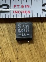
Need source for AVR’s memory capacitor

Harman Kardon AVR 110. Picked up for $10. Has common issue of memory capacitor failure. I’d like to spend as little as possible, shipped to Georgia, USA. Any recommendations? I’m not in a rush so slow shipping is fine. Do I need an “exact” replacement? I wish I could put any old cap in there. Thanks!

PS- leads look short because they broke off as I bent it vertical. They broke off in the middle of the leads, not at the board.

Attachments

  • IMG_3401.jpeg
    IMG_3401.jpeg
    411.8 KB · Views: 90
  • IMG_3398.jpeg
    IMG_3398.jpeg
    306.5 KB · Views: 106
  • IMG_3399.jpeg
    IMG_3399.jpeg
    325.7 KB · Views: 86
  • IMG_3400.jpeg
    IMG_3400.jpeg
    327.5 KB · Views: 81

WTB complete solid state stereo amp or SS / tube preamp you've built

I'd like to buy someone's solid state amplifier, CONUS, preferably class AB, or a SS or tube preamp. I'm redoing my system and no time / energy to build something myself. And, frankly, commercial stuff just doesn't impress me much anymore on performance relative to cost

Let me know what you have with $ and pictures, again CONUS only

Newbie

Greetings from the far reaches of Rhode Island. No, it's not even an island!

I first fell in love with soldering in the late 1960s building a Heathkit stereo receiver. That was followed by several other Heathkit projects. I have done several re-caps of old music equipment, and am currently rejuvenating a McIntosh C22 (very first model). I recently build a Moog Model D clone (with SMDs, no less!) and am about to start its final testing and calibration. I got 2/3 the way through building a 176 compressor from Drip Electronics, but that is paused indefinitely until the designer/owner of Drip follows through with answering questions -- a topic for another day :-(

I just successfully upgraded the power supply on my trusty Linn LP12 and I am about to re-cap and calibrate two Hickok 752A tube testers. A complete overhaul of a Phase Linear 400 (a very early model) is next up on the docket. Now that I am retired, every day is Saturday and I have more time for all these projects!

-Jon

Troubleshooting speaker showing mega-ohms of resistance?

Prologue:
I realize, for example, a passive “8 ohm nominal” rated home speaker’s impedance/resistance will vary greatly when being used, but will “generally” (in my experience) measure somewhere roughly between 4 and 10 ohms when at rest.

So, when I pick up used speakers, I’ll measure their resting impedance before hooking them up to my amp for no other reason than to make sure there isn’t something wacky going on that might trigger my amp’s protection circuitry or otherwise harm it.

I picked up some used klipsch speakers (2 way, 2 woofers + 1 tweeter, nominal 8 ohm). One measures 15 megaohms and the other measures 21 megaohms.

That seems way out of the ordinary so I opened them up. I disconnected the tweeters and woofers and they all measure what you’d expect on their own (something like 5-ish ohms). Not shorted and not “open”.
So now I’m looking at this crossover and trying to figure out where to start looking for problems. Nothing appears “wrong” based on appearances. No bulging caps, or burn marks, etc. My first thought was that thermistor, but (in circuit) it measures 0.4 ohms, which seems reasonable. Am I wasting time measuring any of the components “in circuit” or must they be removed, the caps are glued to the board and will have to be pryed off.

Attachments

  • IMG_3752.jpeg
    IMG_3752.jpeg
    193 KB · Views: 105
  • IMG_3754.png
    IMG_3754.png
    647.3 KB · Views: 91
  • IMG_3755.png
    IMG_3755.png
    622.3 KB · Views: 90
  • IMG_3753.png
    IMG_3753.png
    612.1 KB · Views: 84
  • IMG_3756.jpeg
    IMG_3756.jpeg
    236.8 KB · Views: 83

For Sale Audio garage sale - 18'' H-frame open baffle subwoofer

Moving away. Need to clean spaces.
The frame measurement is made based on Martin King's measurement/simulation.
http://www.quarter-wave.com/OBs/U_and_H_Frames.pdf

The H-frame sub has great deep bass up to 250 hz or 400 hz depends on how you adjust your cutoff frequency with your crossover. I found the ideal XOVER point is 160 hz, 180hz, 200hz, 250 hz. Depending how you want to blend it with your Fullrange drivers

Drivers are Goldwood Sound GW-1858. I chose the driver based on Martin's recommedation for 18'' open baffle driver based on his measurement. I tested out and it sounds amazing with my open baffle speaker system.
Size : 23'' x 23'' x 16''

Asking price 100 usd for the pair frames + drivers.

Thick wood slap panel i'm using to build this project is more than my asking price.

Located in San Diego, CA. Local pickup is encouraged due to size and weight of the driver and material.

3177e0d5-6b34-4ce8-b7de-7bb11e34c9ca

a66e5f2d-6c41-47fb-9b36-789fbf7fba4e

3486bff8-293e-4296-be30-a7ab312880b3

746c891b-6e9f-4f09-bfe9-69ab6b6c86bb

Cambridge CXA60 vs Simaudio Moon I.5 (220i)

Hello guys,

I currently have a Kenwood C1 and M1, or a Cambridge Audio Topaz SR10. The differences between the two are pretty minor from what I am hearing coming out of my speakers so I currently use the Topaz as it has a remote. My DAC is a SMSL C200, my Phono stage is a Clearaudio nano v2 and I use a Technics 1210 MK5.

I loved the Kenwood stack and it was a noticeable upgrade from my previous NAD 3155.

The speakers I use are Audio Physics Yara 2 compacts, they are not optimally placed at all, they sit above a wall to wall desk on fairly cheap wall mounts, and one speaker is basically in a corner. I can do up to 4 or 5 inches away from the back wall and the corner speaker is about 6 inches away from the side wall.

The reason I want to upgrade is because I am having some issues with the Kenwood, it recently blew the tweeters on my B&W CDM1 SE's, and I also find all my speakers fatiguing. People advised me that if I find the B&W's and the Audio Physics fatiguing, its probably the amp that needs a change. I personally think it is also due to placement of the speakers. They are about 4.5' apart and angled in a bit as I listen from the back of my room but also from the desk when I am at my computer. They are most fatiguing when I am sitting at the desk. The only speakers I do not find fatiguing at all are Totem Mites, and I had these powered by the Kenwood stack. The only problem is that they lack bass, and I can't always have the subwoofer on as it is somehow louder in the rest of my house than in my room at listening levels.

I found a Cambridge CXA60 and a Simaudio Moon i.5 (not i-5) (its apparently the same as the 220i, I do not know why it has two names).

The Simaudio moon will cost me 100 CAD more plus shipping, the CXA60 would not require shipping.

I bought the Audio Physics Yara 2 speakers because I found the B&W's too fatiguing in my small room, and I did not get a good soundstage illusion from them with the very improper positioning I have to use. The Yara 2 do much better with soundstage in my setup but are still somehow fatiguing.

What kind of upgrades could i expect from the two integrated amps I can purchase and which one would you guys reccomend? Would buying something cheaper also be an option? I would be spending 100 to 200 CAD more on the amplifier then on the speakers themselves so I do not know if that is money well spent or not.

Some people also recommended tube pre amps to lessen the listening fatigue, but I do not have room for a tube preamp as my amps are hanging from the underside of my desk, and the desk space is taken up by the Turntable and computer system.

Thanks a lot!

Transformer help for 6V6 - RCA SP10

I'm DIY building the RCA SP10 push pull 6V6 10 watt amp and I have a question about what output transformer to use for best sound.
Wondering if some of you will more experience can help out here. I understand some of the design rules - but then there seems to be a lot of "bending" of said rules.

The RCA Tube Manual RC19 has the schematic in the "circuits" section - calls out 9k-10k output transformer impedance.
https://mysite.du.edu/~etuttle/electron/circ287.gif

I have a hard copy of the the 1954(?) SAMS photofacts for the RCA SP10 and the transformer is listed at 8.7K - close to the 9k.
I've seen other DIY schematics using the 8k on the internet.

My selection I have for transformers are from EDCORUSA and are 8K or 10k (10 watt) version
CXPP10-10k (10K) EDCOR - CXPP10-10K
CXPP10-8k (8K) EDCOR - CXPP10-8K

So which one? Or does it really matter? Three IS a 20watt EDCOR that's 8.6k but it's more $$ and larger and seems way overkill.

If it matters - while both EDCOR transformers have 4 ohm and 8 ohm taps - I'll be using (mainly) the 4 ohm taps for my speakers.

Speakers

Hey everyone,

Exciting news! I managed to get my hands on 2 Low Rider 18" Peavey speakers in 8.5 cubic foot enclosures tuned to 30 Hz. The enclosures are built with 3/4 birch ply, doubled in the front and rear, and have two six-inch ports, each twelve inches in length. Tomorrow, I'll be powering them with an EP2500 and using the built-in high pass filter at 30Hz (although I'm considering 25Hz). I'm also curious about speaker break-in. Should I go easy at first, or can I let them rip right out of the box and break in over time?

Would love to hear your advice!

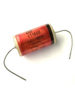
Ero KT1800 capacitor

I have some Ero MKT 1800 capacitors, 0,1uF, that I want to use in my DIY 6v6 pp amp. There are a black"ring" on one side of the capacitor. How to connect the capacitors in the curcuit, between the stages? The black ring to the input or output stage? The black ring against the 100k resistance or against the 270k resistance?

https://diyaudioprojects.com/Schematics/DIY-Push-Pull-PP-6V6-Tube-Amplifier/

Attachments

  • ero-kt1800-capacitor-022uf-1000vdc.jpg
    ero-kt1800-capacitor-022uf-1000vdc.jpg
    99.7 KB · Views: 83

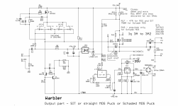
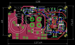
Warbler; Mos/Schade MOS/SIT choke loaded follower power amp

These are not really my Cup of Tea, but there are few Greedy Boyz gnawing me about this...... so finally

as usual - basic pics in this post

I did forgot any pics taking apparatus today, going to my Workshop, so didn't took in vivo pics of T -Bed; will do that tomorrow when doing SIT ( two iterations of it) arrangement and tests

with this one - name of the game is to get trouble free and steady Iq setting, while having all variations named in title, by wish

EDIT on 16.07.2022. - Revised schematic and measurements, starting from post #30

Attachments

  • Warbler Eagle sshot.png
    Warbler Eagle sshot.png
    45.2 KB · Views: 1,145
  • Warbler top render.png
    Warbler top render.png
    493.1 KB · Views: 549
  • Warbler bottom render.png
    Warbler bottom render.png
    399.4 KB · Views: 1,124
  • Warbler schm.png
    Warbler schm.png
    180.7 KB · Views: 2,032

New Member problem with JL Audio JX500/1

Hi diyAudio Team members, my name is Alfonso, Im from Mexico, Im Electronic Engineer and I love the car audio, as a hobby, Im starting to repair subwoofers and power amplifiers.

at this moment, I have a JL Audio JX500/1 that had the power supply mosfets and a couple of BJT transistors damaged, I replaced all of the for brand new components, same batch, the transistors replaced were:

8 RFP70N06 (not sure if those are the original ones, it looks like those were replaced at least once before)
4 TTC5200, original ones were from toshiba, but I bought brand EVVO, I got them from digikey
4 TTA1943, original ones were from toshiba, but I bought brand EVVO, I got them from digikey

I checked the fets driver TL494CN with a scope, it is wirking fine, after that, I turn the amp on and it changed from protect to power mode, I connected a subwoofer and it looks like it is working fine, but after around 10-15 mins working, the output stage section is It's heating up very fast, power supply stage is very stable and is not hot, I decided to turn the amp off before it get damaged again.

The output driver transistors used in this amp are the TP41 and TP42, I dont know if those are the originals or were replaced before, in some threads I read that these transistors are not good as drivers, d you know if these transistors are the original ones used by this amp?

what can be causing that the amp is heating up very fast only in the output power transisitos (C5200 & A1943)? something else that I can check?

I really appreciate your help.

Thank you

Vincent SP-T800 Power Amplifier DC Volts on Speaker Output Terminals

UPDATE: Problem Solved
Swapped V101 12AU7 Tube from the other identical Amplifier and behavior normalized.

Culprit was the The 12AU7 Tube.
Swapped the tube to the other amplifier to cross check other parts.
The behavior shifted.

Case Closed!


Hi Everyone!

It all Started when i noticed my Left Speaker Woofer drivers moving in & out Slowly, flexing too much,even when there was no input signal from my pre-amplifier.

After some troubleshooting & exploring internet and measured dc voltage on output terminals of my speakers and measured abnormal readings from one of my amplifier.

Amplifier in question is Vincent SP-T800 Power Amplifier Monoblocks with Tube Input Stage.

Cross checked with the other amplifier and noticed my left monoblock is measuring dc volts from 2.0mv to 1.0v and fluctuating back and forth on both speaker A & Speaker B.

I am sharing some videos for reference.

Unfortunately there is no service from Vincent in my country and also these amplifiers are over the warranty period anyway.

I can import small replaceable parts like Resistors or Capacitors or Tubes if Required.

Login to view embedded media

https://www.connect.de/testbericht/endverstaerker-vincent-sp-t-800-329060.html

https://www.hifi-regler.de/p/vincent-sp-t800.html

ADCOM GFP-750 Upgrade

Our audio shop has closed due to retirement and I would like to share our mod for the GFP-750. I hope that this will help some of you who would like a little better sound quality but the mod will improve clarity first and foremost. It is already a terrific performer designed by Nelson Pass and is similar to the Pass Aleph P.

Attachments

  • Like
Reactions: Frabor and NormB

Attempting an open baffle build - some newbie questions

I recently posted a thread inquiring about building the Linkwitz LX521 baffle part and filling in the low end with a conventional subwoofer. Lots of helpful comments, but mixed predictions for success. Links supplied in that thread got me started reading about building open baffle speakers (not ALL of the 224 pages in the open baffle speaker thread, though), and while I have never build a speaker before, this encouraged me to build something from scratch.
I was pondering a Caladan or Pure Audio clone using the Beyma woofers from the Caladan and a GRS PT6825-8 mid/tweeter that many people seem to recommend, and then using a multichannel amp and a miniDSP for cross-over and EQ. Being a newbie, this lead to some initial questions (there probably will be more down the line):

1. The GRS PT6825-8 often seems to be combined with an additional tweeter, since there's a bit of fall-off after 10 kHz. Given that I don't hear much beyond 11 kHz (yes, I'm getting old) and the potential for EQ, can I safely omit the additional tweeter?

2. The Pure Audio speakers use modular panels for each driver, which I find very appealing, as the smaller panels will be easier to handle and allow to be individually angled. Putting the panels at an angle probably addresses some timing/phase alignment issues, but that can probably also be done with the DSP. Are there any other accoustic advantages/disadvantages? Is the small gap between the panels of any concern? The Trio10 has the two woofers on the bottom and the tweeter on top, the Trio15 has a woofer-tweeter-woofer arrangement. Is one arrangement superior to the other (when using 12" drivers, there are 10" in the Trio10, I believe)?

3. Where can I find those feet/stands that are shown on page 2 of this thread?

4. I plan to get an 8-channel amp (more flexibility for future changes). I could get a model with the cheaper 125W/c NC122MP Hypex modules and drive each woofer from a different channel. Would there be any benefit for eq'ing each woofer separately? I read a comment somewhere that the lower woofer might benefit from a 200 Hz cutoff, but no explanation or reason was given (due to being lower to the floor?).

Mounting the choke directly beneath the PT?

I have a Hammond 374BX power transformer and a Triad C-14X choke, and was wondering it there are any issues mounting the choke directly below the PT inside the chassis (for the Simple SE)? From what I can tell, the axis of the choke winding is vertical, whereas the Hammond winding axis is horizontal (I think), so my understanding is that they shouldn't have massive coupling. But is this a bad idea in general? Has anyone else tried this?

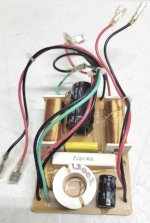
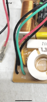
which parts should I replace in this crossover? (schematic inside)

so I need to repair a crossover and thought it would be an "improvement" if replace some other parts.

  • 15 + 22 + 100uF are all bipolar 100V caps. I'm thinking of replacing those polypros (assuming the equivalent ones will fit)
  • replacing the 3.3 + 6.8uF 250V with something with "better" quality ones like maybe solen or wima. The ones currently used seems to be the cheapest you can find at aliexpress.
thoughts? perhaps you have other suggestions? Thank you!

PS: Please assume the schematic is correct. It was derived from the PCB by tracing the connections between components using a multimeter.

Screenshot from 2024-09-04 20-40-52-edited.jpg

Frequency doubler for arbitrary input

Hello,

I want to implement a simple circuit, to double the frequency of a digital input signal. However, the design goals are somewhat odd.

Input signal is: a pulse train of 2-4 pulses, frequency ranges from 0.5Hz to 10.67Hz, and duty cycle is around 15-16%.
So, I would like to double this input's frequency, while roughly retaining the duty cycle.

Is this possible for example using flip flops only, or is a small microcontroller the smallest solution? I have seen designs that utilize a delay line and an XOR gate, but I figure that since my frequency varies so much, I will not be able to set an acceptable delay line for all input frequencies.

Suggested capacity box BMS 18N862

Hello everyone. I am new to this forum. I have just started working on a final project for a subwoofer. I am trying to use dedicated software, but they are all too professional for my skills.
I have read everything I could about the BMS 18N 862. And it seems like the perfect candidate. I will have to make a pneumatic suspension (closed cabinet) with not very high SPL. Let's say 100/103 MAX, in 90% of the use they will be at 78/90DB. I will use only 1 driver.
However, I would like it to reproduce linearly from 20 Hz to 100/300 (depends if the bms sounds better than my pl200 audio monitors) from 100 Hz up. I have two powersoft litemod modules as final amplifiers. One in bridge mode allowing a rms power of 1200 W and the other 600 W per channel for 2. Both connected to its Loto DSP.
The idea is to drive the subwoofer with the bridge module, and the woofers of my pl200 from the 2-channel module. So as to have 3 total channels.
While for the high channels I will have a Purifi ET400A (eval 1) without dsp.
The question is: I have read a lot about this subwoofer and I have doubts about the usability. I would lean towards a capacity of 125 liters. The parent company suggests 100. But do you mean 100 liters net or gross? Because from the software simulation it changes a lot. 100 liters net will be about 130 gross.
The room is 5x5 meters. Height 3MT

Attachments

  • sub buona top.png
    sub buona top.png
    250.8 KB · Views: 105

Trying to understand the source of intermittent 60Hz Hum

I have a fix for this, but I'm trying to understand exactly what is causing it.

The amp is a Headphone amp (though it would certainly drive speakers), Hybrid, a Triode strapped C3M Tube stage feeding into a Mosfet source follower, the tubes are mounted to the top of the case, with shielded cable running to the Anode Grid and Cathode.

I'm posting here since the noise is something todo with the tube stage

Basically when I power the amp on sometimes I get a 100+mV 60Hz hum out of one or both channels, If I lift the top of the amp (where the tubes are attached), it modulates the hum, completely eliminating it in some positions, and I can always bring it back by picking particular angles for the top of the case. If I take a lead connected to my ground point and ground the shield of the cable running to the tube at the end nearest the tube, the noise instantly vanishes.

I don't believe it's a bad connection, or anything to do with moving the connections. The tube Heater is DC with < 1mV of ripple, There is no AC anywhere near the right hand side of the case where the right channel is.

I haven't had a chance to run a permanent wire to ground from the shield to verify that fixes it.
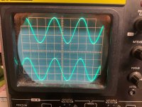
My best guess at this point is, that the aluminum case top is not grounded because of it's coating, and acting as as antenna, but the size of the noise has me skeptical of that explanation, so I'm just wondering if anyone else has experienced something similar, and has a better explanation.

B+ is 150V, the Anode current is ~10mA, there is a 2K2 grid stopper not depicted in the diagram because it's mounted on the incorrectly labelled tube socket.
On the C3M connection 1 is Anode, 2 is Grid, 3 is Cathode

1725384697875.png


And the Case for illustration purposes

1725384933629.png


And the internal layout, Pre boards are at the top on the outsides, Disconnected orange wires are for the tube heaters.

1725385128599.png

Citation 2024

Have completed my Citation II upgrade to a pcb base unit. My post last December 2023 had start hum and buzz problems.
After 8 months have all the problems solved. The new unit I call Citation 2024.
The corrections were the following:

1. New main pcb, left & right channels totally isolated except for power and ground.
2. Added two 50 ohm resistors to ground on each of the 6.3 VAC heater lines.
3. Added .1uF 630Vdc caps on -69VDC and +460 VDC outputs.
4. Added a 10k 1/2w resistor across the 1 M input resistors.
5. Added a Speaker Dethumper relay on speaker outputs. Delay time 45 seconds.

Been running for a week, sounds great .

Attachments

  • Gerber_files.zip
    Gerber_files.zip
    1.9 MB · Views: 57
  • Schematics.zip
    Schematics.zip
    883.6 KB · Views: 116
  • PDF.zip
    PDF.zip
    3.5 MB · Views: 85
  • 2k Dual channel.jpeg
    2k Dual channel.jpeg
    549.8 KB · Views: 129
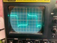
  • 10K square wave.jpeg
    10K square wave.jpeg
    484.4 KB · Views: 113
  • Case_topview.jpeg
    Case_topview.jpeg
    612.3 KB · Views: 115
  • Case frontview w Cover.jpeg
    Case frontview w Cover.jpeg
    442.9 KB · Views: 134
  • Front View.jpeg
    Front View.jpeg
    607.3 KB · Views: 127
Projects by fanatics, for fanatics
Get answers and advice for everyone wanting to learn the art of audio.
Join the Community
507,526
Members
7,875,520
Messages

Filter

Forum Statistics

Threads
405,657
Messages
7,875,520
Members
507,526
Latest member
pqthai