I've had an audiosource amp 310 faithfully serving me for over 9 years. It recently started behaving erratically, and now takes 20 or 30 minutes to eventually come on after being powered up. When but when it does come on, the amp functions just fine. The behavior is consistent regardless of the auto-on settings on the amp. There is no evidence of burnt components or leaking capacitors, so I am guessing there is a bad relay somewhere inside.
I have reached out to audiosource and googled high and low to find any information on this amplifier. There are several posts in this forum related to the amp 200/300 but from looking at the drawings, they are very different from the 210/310.
If anyone has any documentation on the 210/310 or advice generally, I would appreciate you sharing it.
Many thanks!
Brandon
Seems there is a leaky capacitor in the timing circuit for the muting.
Look for a 555 or similar timer (or a discrete muting circuit) and nearby an electrolytic capacitor roughly 100uF or so.
Replace with a low leakage similar value and type, rated at 25V or 35V.
To verify this is the problem, check the output DC offset before the relay. Does it keep less than say 100mV after a short time?
That means the amplifier circuit is ok, and the muting should release (if that works).
I agree with Rayma and knowing what I've repaired on Amp200/300 version in the past - they have a weakness in the low voltage rails. I've seen resistors, rectifiers and caps all cause an issue - but only once have I seen an actual problem with the high-voltage rail and that was the main bridge rectifier.
If yu can post some pictures, close up of the power supply board, and the low-voltage portion that would help us get you back up and running.
If yu can post some pictures, close up of the power supply board, and the low-voltage portion that would help us get you back up and running.
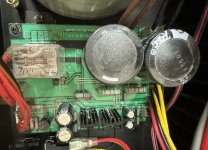
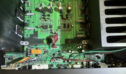
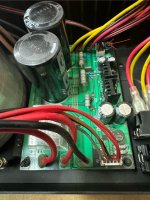
Thanks for the prompt responses. I don't see any 555 ICs, but there are several opamp ICs. I'd need some additional guidance to be able to identify a discrete muting circuit. Attached are photos of the power supply board and the preamp board.
Attachments
Do you have a Digital Multi-meter? Hopefully so - I would start by checking all the voltages, put the black probe to the speaker negative (black) for all these measurements and measure using the red probe with one hand, carefully.
The power supply board in your first picture should have 4-6 wires (Red/Yellow/Black - if it's the same as the AMP200/300) and those got to the amp board and will measure 50-65 Vdc. That's your high -voltage power, you want to confirm it's there as soon as you turn on the amp and stays pretty constant +/- 2-3V.
Next there should be a 5-6 pin connector (much smaller gauge wires) that goes to the amp board and on the AMP200/300 it is actually labelled as 24V, 12V, +/-15V, GND. This is your low voltage wiring. You want to measure each wire at the plug (carefully) and write don the voltages.
This is where you will likely not see the 24V or 12V, until the speaker protection kicks in (as you mention earlier that can take a few minutes) You can try to measure right when you turn it on, and then again 10 mins later and then again 10 mins after that until you gt all the voltages to show on your DMM.
Include a full picture of the amplifier, so we can see the layout of the amp, and can zoom in on the pictures to confirm where else you should measure. My first guess, is you might be missing the +/-15V (likely only one of those voltages, so it won't come out of protection. The voltage rgulators (the small black heatsinks on the power board) die slowly from excessive heat and don't usually die, they just fade and at about 13V, the relay stops kicking in on the speaker protection. A little guess right now, but will now more with your voltage measurements.
You can also measure the resistors around that relay as well - those often go open circuit and don't look burned. I think they are supposd to be 1-ohm.
Here is a picture, might be easier to understand. in the 2nd pic - top left is the high voltage wires, the top middle is the low-voltage wiring, top right is the voltage regulators (+/-15V) and although in a different spot, you can see the resistors I was referring to.
Attachments
Thank you again for your assistance!
Seems as though the high voltage rails function fine. There are two pairs of high voltage wires, red/yellow/black and both pairs measure -65v on yellow, +65v on red and 0v on black.
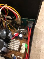
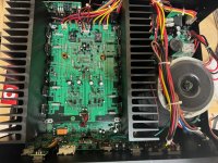
My amp has two connectors each with three low voltage black/red/black wires. See the middle picture, red arrow. One connector goes to the amp board and the other goes to the preamp board. None of them are labeled. After the amp powers on, I measured +15v, 0v and -15v for the preamp connector and +6.5v, 0v, 0v for the amp connector.
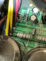
I also measured all the resistors on the power board. Two of the big ones (see middle picture, blue arrows) seem to be open, or at least I couldn't get any reading on them. Is it possible these are burned open as you suggested above? Would the behavior of the low voltage measurements make sense if this was the case?
The other interesting data point -- the amp has been on for an hour now and the speaker protection has not come on. I'm obviously running it without the cover now. There is some heat coming off the unit... is it possible the heat would cause those resistors to close after a while and kick the whole thing on?
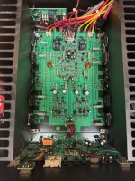
As requested, I included some other pictures of the entire guts of the box. The size on a couple photos was too large to upload, so hopefully these are high enough resolution for what you're looking for.
Thanks again for your help.
Attachments
Last edited:
Those large resistors on the power supply board should be low ohms - likely 10-ohm or something so you need to leave your DMM probes on the legs for a few seconds to get a good reading (EDIT: possibly bleed resistors for those big caps - they could be 1.5k or higher resistance). Unlikely they are open, but they could be high resistance and messing with the function. (EDIT: AMP200/300 uses 6.5k on the high-voltage rails and 1.5k on the low voltage rails.)
Are there diodes between the capacitors and those red/black/red low voltage connections? (Diode is black with silver band on one end) because I'm having trouble understanding why you have +/-15V and only 6.5/0/0 from connections that appear to be coming from the same tracks on the supply board (should have same +/-15V I would think).
when you say heat coming off - is that the large amplifier board heatsinks warming up (how hot - can you put your finger on the top of the fins for at least a few seconds, like 5-10 ) or is the heat coming from the supply board heatsnks? Not sure what you meant by that. As always be careful that you only touch the heatsinks or hover you hand above parts and don't go sticking your finger on a live amplifier part.
with your current symptoms - we are either missing a voltage, have a bad capacitor/resistor (shorting the voltage needed) or worst case a problem with the amp board causing high DC and the protection circuit is stepping in to save your speakers.
Have you measured the voltages at this multi-colored plug? Where does it connect to? Front-panel maybe? Wondering if this might have the power signal (+24V) and possibly the 12V, which I would have expected not the 6.5 you measured to the pre-amp board.
Last edited:
In your photo snippet, the large multicolor connector goes to a daughterboard attached to the front panel. I believe this controls all the LEDs on the front. This model has a ring around the power button, signal indicators (red/amber/green) and a light bar which is selectable via a slider switch on the rear panel. The voltages seem to be +2, +6 or 0.
The connecter behind and left of the large one is connected to the slider on the rear for input trigger. You can choose between trigger, auto-on and normal. When set to trigger both the red and black wires read -7 or -8. When set to auto-on or normal, both wires read +1v. I did take this measurement with a signal actually on the input.
The connector behind and right of the large one is the low voltage connector from the power board. Regardless of what the input trigger slider is set for, the LV amp connector always reads -15/0/+15. The LV connector for the amp, however, changes based on the input trigger. Set to trigger, I get -8/0/0. Set to auto-on I get 12/0/0. Set to normal I get 6/0/0.
There does seem to be a diode just before the LV connectors. See photo. I haven't removed the power board to see the traces on the bottom, but it's right next to it, so I'm assuming it is connected. I also can't really confirm that the two LV connectors are on the same rails, but the voltages seem to move independently from one another given the input trigger setting.
The heat is coming from the big heat sinks on the amp board. Not hot at all... maybe closer to room-temp or lukewarm!
Finally, I tried again to get a reading on those two resistors and can't get it to read. The colors are always hard to tell but it's either 4k or 40k. There are some other (smaller) 2 ohm resistors on the corner of the board which read properly.
Attachments
** caught a typo in my third paragraph above. The LV amp connectors read constant +/-15 volts. It's the preamp LV connectors that seem to change with the input trigger switch.
Thanks again.
Thanks again.
just making sure - but you have your DMM set to Ohms not voltage when you're trying to read the resistor values? DMM usually has a Greek Omega symbol on the dial. Strang you can't get a good reading from them, especially if they are in fact bleeder resistors they should basically have full 65V rail voltage running through them when the amp is on and a diminishing voltage when the amp is turned off.
I guess the best next step would be to capture the low voltages when the amp is working and compare the same voltages when the amp is in protection?
I find it strange, considering the power board is similar to the AMP200/300 that you don't find a 24V and a 12V on these LV plugs. There has to be 24V, likely coming from the amp board and/or front panel board that is switched "on" by a transistor to tell the relay on the power board it's "ok" to switch on.
Might be worthwhile to test the voltage on D38 on both sides (should be close to 24V) and also on both sides of D37, guessing but likely to be close to the 6V on the LV from the preamp board - i.e. controlling the relay if you have the trigger or auto-on feature working. Would measure R204 and R205 to see the resistance, probably ~3-5k if I was guessing.
D38 annode measures 0V. D38 cathode measures 22.3V.
Both sides of D37 measured ~6V
The resistors I was not able to previously read (bleed resistors) have 65V on one side and 0V on the other. I guess they are "bleed resistors" as you describe.
I'm not sure what going on with measuring resistance. I have some measurements but I'm getting wildly different readings when the amp is powered on versus when it is off. Not sure if this is normal... The DMM is set correctly but I'm going to try to find another DMM and try to measure again.
Hi there and sorry for the delay. Audiosource was kind enough to get back to me and sent the schematics for the 110/210/310 amp (attached).
The power board is shown on page 6. My amp is measuring +/- 64v for VCC. The +/- 15v outputs check out. The handful of points marked "AC12V" on the drawing measure 15vac. And the "POWER" indicator (near D37) measures 6vdc. Are those within the margin of error that you would expect?
A new DMM should arrive in the mail tonight.
Attachments
Sounds more and more like you have DC on the outputs and after the amp warms up it is settling down and the relay is clicking in (or coming out of protection)
You can check this by measuring (black probe grounded to the black speaker terminal on the back of the amp) and probing carefully with the red probe, some type of alligator or DMM clips would be even better, so you can clip to the wire with the power off, then switch on and take the measurements
the circled resistors are emitter resistors and will carry audio signal out of the power transistors (AC voltage), basically the amplifier part of the circuit. IF there is DC >1/2Vdc it will trigger the protection circuit and tell the relays not to engage.
measure on each end of the resistor one at a time - if there is DC, you will see it on your meter. Also the amp should be in a protect mode, so no audio playing. Depending on which resistor has DC, will tell you the channel with the problem.
In this picture - Red (P4, P5) is left channel, yellow (P6, P7) is right channel. Hard to tell for sure, so confirm this on the actual board.
Those resistors all measure between 180 and 250mVdc on either side of the resistor.
Confirmed P4, P5, P6 and P7 run through a toggle switch and to the speaker output.
Confirmed P4, P5, P6 and P7 run through a toggle switch and to the speaker output.
Were these measurements when the amp was in protect or working?
Did you tell us which speakers aren’t working or is it both channels that aren’t working when you first turn it on?
Did you tell us which speakers aren’t working or is it both channels that aren’t working when you first turn it on?
All the voltage measurements where while the amp was in protect. None of the channels are working.
I really appreciate your help with this.
I really appreciate your help with this.
Ok that’s good (sorry)… can you take the same measurement on those large resistors when it comes out of protection? 250mV seems low for that amp to protect, but could be.
Wondering if it goes closer to 100mV and then starts working.
Wondering if it goes closer to 100mV and then starts working.
I was finally able to get the amp to come out of protection. It used to come out on its own but now I can only get it to come out by flipping the switches on the back. After trying for about an hour, I can’t replicate a sequence to get it to come on…
The dc on the emitter resistors while the amp was functioning properly was 140 to 160mV.
The dc on the emitter resistors while the amp was functioning properly was 140 to 160mV.
I may be asking a lot - not knowing your comfort of probing the amp when it's live (turned on), but trying to figure out if you have a front-end (DC offset) from the front-end of the amp of possibly a leaking transistor in the back-side (closer to the big output transistors)
I marked a handful of spots to take DC measurements, focus on the Left channel (right side if you are looking from the front of the amp). I tried to mark resistors to take the measurements at, so it's easier and less likely to short out something. That said, it is still live and if you slip the DMM probe you could cause a lot more damage to the amplifier. Not sure if you have one, but this is when a Dim Bulb Tester (incandescent light in series with the power plug) will help limit damage by limiting the current if you do slip with the probes.
You can print out this sheet and write in the DC voltages.
also since it's in protect now - remeasure the low voltage plugs coming off the power supply board (J18 3-pin??)
Up to you - do only what you are comfortable with and feel safe doing.
- Home
- Amplifiers
- Solid State
- Audiosource Amp 310
