Please don’t apologize! You’re the one helping me out and it is really appreciated.
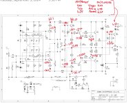
Attached are the various readings, all in VDC.
The power board readings are all the same as they were previously, including 15vac where the schematic indicated it should be 12vac.
Thanks again for your help.
Attached are the various readings, all in VDC.
The power board readings are all the same as they were previously, including 15vac where the schematic indicated it should be 12vac.
Thanks again for your help.
Attachments
Ohh , no current in VAS (Q30-32). R113/115 should have .6 - 1V drop from rails for a 6-10mA VAS.
Input stages and/or current sources are not biasing the VAS to conduct.
OS
Input stages and/or current sources are not biasing the VAS to conduct.
OS
This has slightly more precise measurements around r113 and r115. Also includes a measurement that I missed the first time near q38.
I understand VAS in the context of loudspeaker design, but what does it mean in the amplifier context? It is probably obvious, but I would note that all these readings are taken when the amp is working properly.
I understand VAS in the context of loudspeaker design, but what does it mean in the amplifier context? It is probably obvious, but I would note that all these readings are taken when the amp is working properly.
Attachments
Can you tell me if the "Yellow" 6.8V is with the amp working or in protection? I think you said working, so can you try and get that measurement when it's in protection? I can only assume it grounds out and the voltage goes low, but not 100% sure.
Additionally, thatnks for the measurements above, clears up the VAS question.
Can you remeasure the "blue" points again (going out to at least 1or 2 decimals) - seems like the culprit (if the measurements are correct) is on the positive voltage rail side, and that 0.73V coming off the outputs seems excessive and could be enough to trigger protection (over current??)
The Blue Arrow shows the 149mV on the outputs (DC), so that other 730mV has to go somehwere or there is an open emitter resistor or something.
Most of this circuit should have >1V variance from the postive rail to the negative rail, and transistors shows 0.5-0.7 voltage drop (or forward voltage) - so without 1-2 decimals it's hard to know if the transistor is working, or if the voltage present is correct.
Here are all the measurements to the maximum precision of my dmm. These were all taken with the amp on/playing. There were two of these values that changed materially from my last set of measurements. I tried to double check that I had the right position on the board but I guess it’s possible I measured or recorded incorrectly the last time.
I cycled the power a few times and was watching the voltage on D12 as I powered on and off. It takes about 20 seconds for the voltage to fully drain after turning the amp off. When powering back up, I have been toggling the input select switch to get the amp to come out of protection rather than waiting a long period of time as I had previously. I cannot seem to determine a sequence of how the switches have to be toggled to get it to come out of protection. Sometimes it’s a couple of movements, other times it’s 15 or 20. On the picture, I recorded the voltages at D12 which are different given the different input selection and whether the amp is in or out of protection. I can’t seem to figure out where the “PRT” label on the amp page of the schematic is connected elsewhere…
I cycled the power a few times and was watching the voltage on D12 as I powered on and off. It takes about 20 seconds for the voltage to fully drain after turning the amp off. When powering back up, I have been toggling the input select switch to get the amp to come out of protection rather than waiting a long period of time as I had previously. I cannot seem to determine a sequence of how the switches have to be toggled to get it to come out of protection. Sometimes it’s a couple of movements, other times it’s 15 or 20. On the picture, I recorded the voltages at D12 which are different given the different input selection and whether the amp is in or out of protection. I can’t seem to figure out where the “PRT” label on the amp page of the schematic is connected elsewhere…


