Hi all. working up to a 45 type build and hoping for some assistance.
Some background. I have built Elekit 8900 and 8600 kits. I have been wanting to build my own amplifier from scratch for sometime now. I’ve been watching online videos and read several books on tube amps. To be honest, having no electronics background, my head starts to nod when reading the books—much of it remains over my head. I have a long way to go but I’m slowly getting there.
Time to get my hands dirty and do some building. I learn more by doing than reading. Hoping the book info will make more sense as I go.
To ease into this project, I bought set of 45 mono blocks locally from craigslist with hopes of some simple upgrades and modifications. After this, I will embark on a new build from scratch.
Again, my knowledge is extremely limited, but I’m working on it. Please be patient.
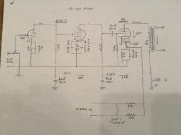
I have poked through the amplifier and drawn up a schematic and measured the voltages. This looks like a possible 45 variant of the JC Morrison 300B design. Even with my limited knowledge, a few issues have already jumped out at me. The first cap in the power supply concerns me and the voltages on the 6SN7 seem low. I would like more voltage across the 45. Also the way the 6SN7 heater voltage has been raised seems unusual.
The knowledge in these forums blows my mind! Hoping to pick up just a little bit of it and enjoy this hobby. Looking for some specific recommendations on voltages and required resistor values to achieve.
Thanks!
EDIT: I am on step one of a two-step process. Step one being modifying the monoblocks on hand has a learning experience. The second step will be building a 45 from scratch based on what I learn in step one.
As stated above, I already own an Elekit 2A3 and 300B amplifiers and will be staying with a 45 build and modifying these monoblocks first.
These mono blocks are a pretty cool junk box type build with some cool vintage bits, but I suspect the builder used what was on hand for resistors and caps and there may be room for improvement. I am not going to do a complete redesign of these amps. I want to stick with the original design and drivers.
In a nutshell, I am looking for:
1. any obvious or dangerous design flaws (bleeder resistors, and such… I got a nasty shock 10 minutes after unplugging… No tubes installed. My bad. Fortunate I didn't kill myself...hope others can learn from my mistake. This **** is real.
2. more voltage across the 45.
3. increase voltage to the 6SN7 to get closer to a linear operating point.
All within the constraints of the current power transformer...ie. resistor and capacitor tweaks. Looking for improvement, not perfection at this point.
Some background. I have built Elekit 8900 and 8600 kits. I have been wanting to build my own amplifier from scratch for sometime now. I’ve been watching online videos and read several books on tube amps. To be honest, having no electronics background, my head starts to nod when reading the books—much of it remains over my head. I have a long way to go but I’m slowly getting there.
Time to get my hands dirty and do some building. I learn more by doing than reading. Hoping the book info will make more sense as I go.
To ease into this project, I bought set of 45 mono blocks locally from craigslist with hopes of some simple upgrades and modifications. After this, I will embark on a new build from scratch.
Again, my knowledge is extremely limited, but I’m working on it. Please be patient.
I have poked through the amplifier and drawn up a schematic and measured the voltages. This looks like a possible 45 variant of the JC Morrison 300B design. Even with my limited knowledge, a few issues have already jumped out at me. The first cap in the power supply concerns me and the voltages on the 6SN7 seem low. I would like more voltage across the 45. Also the way the 6SN7 heater voltage has been raised seems unusual.
The knowledge in these forums blows my mind! Hoping to pick up just a little bit of it and enjoy this hobby. Looking for some specific recommendations on voltages and required resistor values to achieve.
Thanks!
EDIT: I am on step one of a two-step process. Step one being modifying the monoblocks on hand has a learning experience. The second step will be building a 45 from scratch based on what I learn in step one.
As stated above, I already own an Elekit 2A3 and 300B amplifiers and will be staying with a 45 build and modifying these monoblocks first.
These mono blocks are a pretty cool junk box type build with some cool vintage bits, but I suspect the builder used what was on hand for resistors and caps and there may be room for improvement. I am not going to do a complete redesign of these amps. I want to stick with the original design and drivers.
In a nutshell, I am looking for:
1. any obvious or dangerous design flaws (bleeder resistors, and such… I got a nasty shock 10 minutes after unplugging… No tubes installed. My bad. Fortunate I didn't kill myself...hope others can learn from my mistake. This **** is real.
2. more voltage across the 45.
3. increase voltage to the 6SN7 to get closer to a linear operating point.
All within the constraints of the current power transformer...ie. resistor and capacitor tweaks. Looking for improvement, not perfection at this point.
Attachments
Last edited:
The first cap after the rectifier is rather big. But if the 6AX5 survives startup...again and again. It will probably last forever. No harm reducing that to say 8uF or so to be on the safe side.
I'ver never seen the heater voltage referenced like that. But that doesn't mean it is wrong...since you want to tinker. Do it the "traditional way" and compare.
Have you listened to this amp? Impressions?
I'ver never seen the heater voltage referenced like that. But that doesn't mean it is wrong...since you want to tinker. Do it the "traditional way" and compare.
Sure looks like it.This looks like a possible 45 variant of the JC Morrison 300B
Have you listened to this amp? Impressions?
Hi. Thanks for the response. Yes I have listened to it and it sounds pretty good! but I did buy it to tinker and learn.
I will try a small first cap in PS but my vague understanding is that may reduce the B+? Doesn’t quite make sense to me how that works, but that’s why I’m here—to learn. also, thinking, increase second cap and maybe bypass with film. The choke however, is tiny and of unknown design. Any danger with bigger 2nd cap?
I will try a small first cap in PS but my vague understanding is that may reduce the B+? Doesn’t quite make sense to me how that works, but that’s why I’m here—to learn. also, thinking, increase second cap and maybe bypass with film. The choke however, is tiny and of unknown design. Any danger with bigger 2nd cap?
It does...but only below a certain value. Depending on how much current you are drawing...In this amp probably only below 4uF or so.but my vague understanding is that may reduce the B+
Last edited:
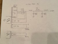
ps. I doubt the secondaries are 250-0-250. Don't see how you can get 300+ from that. Even with 300V secondaries I can't get above 300v b+.

No. Download this ...very handy. https://groups.io/g/duncanampspsud. And you'll get warnings if the rectifiers anything is exceeded.Any danger with bigger 2nd cap?
Here is a guide I translated: https://www.dhtrob.com/overige/pdf/dhtrob_psu.pdf
If fact you will have to increase the 2nd cap to reduce ripple. Reducing the first cap increases the ripple quite a bit as you can see in psud.
Very cool! Exactly the type of information I am looking for. The transformer is marked 250 V per leg, but measures 284V. I’m guessing that is because it is a 117 V transformer running on 125 V mains. Possibly the low load of a 45 mono block contributes to the higher voltage also? Appreciate the input! Have to run. Will be checking back later.
Edit. Looks like you put in a 300 V transformer. It is a 500 V transformer…250v per side. Sorry my schematic drawings aren’t the best. First time I’ve drawn one. Then again you did mention 250-0-250. Not certain I am communicating this properly or understanding the PSUD diagram.
Edit. Looks like you put in a 300 V transformer. It is a 500 V transformer…250v per side. Sorry my schematic drawings aren’t the best. First time I’ve drawn one. Then again you did mention 250-0-250. Not certain I am communicating this properly or understanding the PSUD diagram.
Last edited:
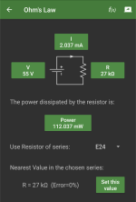
Indeed...though I put in 100mA..in the sim. If you use ohms law: 47V across a 1.5k resistor comes to around 31mA per 45= 62 for both.Possibly the low load of a 45 mono block contributes to the higher voltage also?
55v over 27k resistor = around 2mA. so 4mA...and 1 v over 470R for the first half of the 6sn7 is another 2mA per channel. So 62+4+4=70mA total...ballpark.
PS. I use electrodroid app on my phone...very handy also for calculating how much watt is 'consumed' by the resistor.
Attachments
70mA. But all is good...this is a simulation after all. It's good that you get higher than 300V...in real life.

Only one running one channel…separate ps for each monoblock. . Also, not sure I understand the PSUD diagram, but should that be a 500 V transformer? 250v per side side? very much appreciate your help! Already learning!per channel
edit. You beat me to it! Thank you!

The secondaries of the power transformer are probably higher than 31 Ohms..Anyway...this shows everything is as it should be.
It is per leg in this case. So your power transformer is 250-0-250. And that is what you feed psud. (Obviously I would feed it 284 because 117 transformer on 125V power.
250v per side side?
Will download that program! Awesome! How much B+ would be lost by going to a 22 UF first cap? I have such a solon film cap I might drop in.
Hi all. working up to a 45 type build and hoping for some assistance.
My question may seems strange, but : is the tube RCA 45 reissued today, as the 300B is ?
T
if the 6SN7 anode voltages noted are correct the 6SN7 will not run well as a driver at such low voltages. The current falls so low that linearity is degraded. This design was seen originally for 300Bs (in the 1990s), where it gets higher voltages.
Actually, IMHO it makes a fairly poor driver valve at any voltage.
If you ar feeding the amp with the usual DAC outputs of 2.0V rms, a 45 driver should be possible with only a single triode, and sound much better for it. It's worth searching the forum for 2A3 & 300B driver circuits to see what can be done, and the voltages required.
You can increase it somewhat, but keep in mind that at the power-ON instant, the choke does very little to limit the cap's inrush current, beyond the 220 Ω of ESR. You can monitor the startup-current in PSUD2, and compare it to the data-sheet values. Respsecting the different current limits of valve rectifiers is worth careful study.Any danger with bigger 2nd cap?
No b+ lost.Will download that program! Awesome! How much B+ would be lost by going to a 22 UF first cap? I have such a solon film cap I might drop in.
Emission labs makes one. Expensive though.My question may seems strange, but : is the tube RCA 45 reissued today, as the 300B is
- Home
- Amplifiers
- Tubes / Valves
- 45 type SET build need assist