Balanced Volume Controller / Line Stage
- By alexcp
- Analog Line Level
- 244 Replies
This is a series of high performance balanced active volume controls with differential input, ground-sensing output (goodbye cross-channel ground loops!), and a choice of analog or digital volume controls (sample Arduino sketches for the latter are included):
All versions feature:
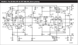
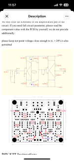
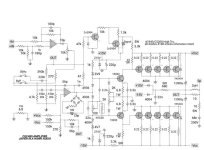
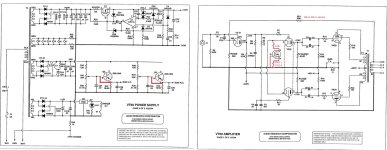
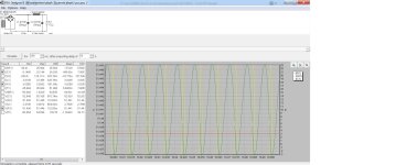
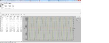
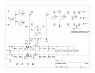
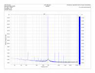
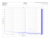
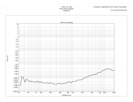
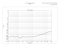
Attached are the schematic and measurements for the analog pot version. My soundcard (E-MU 0204) is not good enough to measure the distortion of this thing at 0.0005% at 1kHz - please look at the baseline plots of the soundcard with its input connect directly to its output. Also, note the difference in PSRR between NE5532 and LM4562.
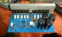
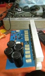
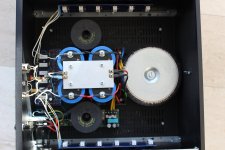
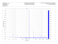
The last plot is one ground referenced channel of a stereo LM3886 amplifier (with one power transformer and one power supply shared by both channels and the line stage) driven by this line stage in its ground sensing configuration. I used my own LM3886 PCBs.
UPDATE: boards are available at HiFiOcean.com.
UPDATE2: a single-ended volume control based on DS1882 is added - it includes a Firstwatt B1-style JFET buffer and a low-noise regulated power supply, all on 1.1x1.1in (28x28mm) board.
UPDATE3: Sample Arduino sketches to control any of the above mentioned digital volume controls are now available on GitHub.
All versions feature:
- Balanced differential input with excellent common mode rejection - works very well with single ended sources, too!
- Output stage that can be configured as balanced (best for downstream stages with differential input) or ground sensing / ground cancelling (best if followed by a single-ended input referenced to its local ground - the vast majority of audio power amps are configured this way).
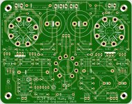
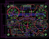
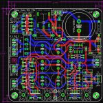
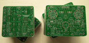
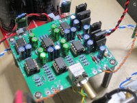
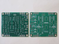
- Compact (2.9x2.6in or 74x66mm) two layer PCB, all though hole parts (except WM8816/MAS6116 and MUSES72320, which only come in surface mount packages)
- Can be part of an integrated amplifier (great with LM3886 or similar chipamp based power stages); an output stage of a DAC to form a "digital preamp"; with an input selector, a high performance balanced line stage / minimalist analog preamp.
Attached are the schematic and measurements for the analog pot version. My soundcard (E-MU 0204) is not good enough to measure the distortion of this thing at 0.0005% at 1kHz - please look at the baseline plots of the soundcard with its input connect directly to its output. Also, note the difference in PSRR between NE5532 and LM4562.
The last plot is one ground referenced channel of a stereo LM3886 amplifier (with one power transformer and one power supply shared by both channels and the line stage) driven by this line stage in its ground sensing configuration. I used my own LM3886 PCBs.
UPDATE: boards are available at HiFiOcean.com.
UPDATE2: a single-ended volume control based on DS1882 is added - it includes a Firstwatt B1-style JFET buffer and a low-noise regulated power supply, all on 1.1x1.1in (28x28mm) board.
UPDATE3: Sample Arduino sketches to control any of the above mentioned digital volume controls are now available on GitHub.
Attachments
-
 avc+s sch left ch.png24 KB · Views: 7,628
 -
 SC loopback.png37.2 KB · Views: 7,221
 -
 AVC balanced.png37.2 KB · Views: 5,997
 -
 thd+n 1kHz avc LM4562.png37.4 KB · Views: 5,864
 -
 thd+n sc only.png23.5 KB · Views: 5,814
 -
 thd+n avc.png22.9 KB · Views: 1,401
 -
 thd+n avc lm4562.png23.1 KB · Views: 1,296
 -
 AVC+LM3886 ground sensing.png39.1 KB · Views: 1,570
 -
 IMG_0732.JPG102.5 KB · Views: 3,939
 -
 IMG_0737.JPG86.9 KB · Views: 3,044