The "Active" Paradigm Export Monitor Upgrade

I've had a pair of Paradigm Export Monitor speakers from 1989 for years, a hand-me-down from my uncle who had them since new. They aren't bad at all, though a little boomy on the low end, and responded well to parametric EQ via miniDSP.

Paradigm | Bookshelf | Monitor | Classic Collection | Export Monitor | Specifications

It's time for their refurbishment and, hopefully, upgrade. I have lots of DIY experience building amps and preamps and all kinds of digital sources, but this is my first loudspeaker project, so I hope to learn a lot along the way.

I intend to make this an active pair, using a miniDSP 2x4HD for crossover, and driving the woofer with my Hypex nCore 400 monoblocks. Tweeter amp is TBD (suggestions welcome), but I'll cable up something for testing purposes when I get to that.

The speaker is of good construction, but no more than that. Bracing is only adequate, and it was stuffed with a tremendous quantity of now-shifting and unglued shredded cotton. The cabinet definitely needed more damping.

Because additional bracing isn't really going to be convenient, I decided to dampen the cabinet walls with Stinger Roadkill, a heavy Dynamat alternative - foil over butyl backing. This was applied everywhere on the interior, resulting in a significant reduction in resonance. The butyl product was also applied to the port exterior, which reduced its tendency to ring.

I took out the crossovers, and will wire the drivers directly to the four binding posts (to be replaced) on the back panel. Tweeter will have a 50uF capacitor in line for protection.

Memory foam will be used on all cabinet walls, and I will experiment with whether to stuff the cabinet in the OEM cotton, or use additional memory foam, depending on measurement results.

I'll be posting pictures and updates as I make progress. Any feedback, tips, or commentary welcome!

Need help with dynaco st70

I have this st70 and need help adjusting the bias... it has 6 pot adjustments, I think the four outer ones are for the output tubes but not sure about the two center ones?
Also I have two sets of output tubes gold lion kt66 and EL34, what do I set the bias voltage to? Is it the same for both sets of tubes? And what are the center pots for? How do you adjust those and to what voltage?
Any help would be appreciated.... I’ll try to post pictures of the amp inside and out so you can see what was done to it...
I’m new to this tube amp stuff.

Attachments

  • 036F8579-DF20-4B50-B647-EF4756461A74.jpg
    036F8579-DF20-4B50-B647-EF4756461A74.jpg
    739.2 KB · Views: 226
  • B2D7D0D1-4AFA-44D3-9BBF-266D69F7C1E4.jpg
    B2D7D0D1-4AFA-44D3-9BBF-266D69F7C1E4.jpg
    1,012.2 KB · Views: 213

SSE blowing fuse - could it be the xformer ??

I've been running my SSE for 4+ years. Always solid. I just moved the rack, powered up and it worked for two days. Then the next time powered on - the fuse blows right away. Strange, replaced it and pop again.

So started trouble shooting, nothing obvious - burnt or smoking. Worked backwards and finally I'm only left with the Hammond 274BX hooked up to the fuse and power switch - all it's secondaries disconnected from the PCB. Flip the switch and the fuse blows. I can't find any shorts other than the primary is reading zero ohm across the 110V in - was expecting at least a few ohms. I've never heard of a transformer going bad over time, but I just don't know what else it could be - very strange.

Anyone seen this before? My next step is to order a replacement as I don't know how else to debug any further. Thanks for any and all feedback.
Michael

Complexmaths

Hi to u all. I am stuck with a problem for which I need your help. I want to solve a complex equation but I do not know how to proceed. The equation is given below.
1=(1+(0.7Mhz/0.7Mhz)2)(1+(0.7Mhz/3Mhz)2)(1+(0.7Mhz/18Mhz)2)
The 0.7Mhz is the first break frequency of an amplier response curve. 3Mhz and 18Mhz are the other break frequencies. I am eager for any sound explanations and thank uin advance

Wanted to Buy Audax MH130Z0 Aerogel or a pair of Scan-speak 18M/4631T00 drivers

I would like to buy a pair of Audax HM130Z0 Aerogel Midrange Scan-speak 18M/4631T00 or Satori MR16P-4 drivers like-new or good condition for a fair price.

I only interested in the mentioned drivers!

The Audax will be matched with a par 5" Gorlich Podzust midrange driver (I have at hand).
The Scan-Speak and Satori 6.5" drivers and both sensitive enough alone.

My first preference would be the Audax but I could use the other two drivers also.
Only the mentioned Audax Aerogel midrange good for me!

If I can't find Audax (first preference) I could use the Scan-Speak midrange drivers or the Satori MR16P-4 the 6.5" drivers alone would provide enough mids for the pair of 10" woofers I will use in my project.

I prefer offers from Canada to avoid the high shipping cost or the import duty.

It is not urgent but at the same time, it would be great to know the size and plan of the enclosures.

Please let me know if you have a pair and you are not planning to use them. 🙂🙂 Thank you!
Payment via Pay Pal unless you live in Toronto near to me, that case can pay cash of course.

Thank you

Attachments

  • HM130Z0_5000x.jpg
    HM130Z0_5000x.jpg
    284.8 KB · Views: 418
  • hm130z0.jpg
    hm130z0.jpg
    162 KB · Views: 359
  • download.jpg
    download.jpg
    5 KB · Views: 340

Mark Levinson No 335 - NO Bias in one channel / NEED HELP

Hi guys,
i am new in this forum, hopefully you can assist me...

I have a Mark Levinson No 335, few weeks ago one channel had distortion and not working correctly.
I decided to inspect it and at the same time to perform the recommended from Mark Levinson upgrades, as well as a re-cap with CDE DCMC caps.

During inspection, i found out that the problematic channel has no bias at the power transistors. And it is not possible to adjust it from the relative potentiometer.

At the same time i found out that the -REG voltage is lower than the +REG (max. 102-103 V DC, instead of 115 V, while the +REG can be adjusted normally at +115 V DC).
The strange thing is that when i try to adjust it, i can not go higher than 102-103 Volts and when i keep turning the potentiometer the voltage drops again. In other words, the max voltage of -102/103 V achieved when the pot is in the middle position, turning it to both ends the voltage is reduced....!

The -PRE_REG voltage can be normally adjusted at 2,1 Volts.

I have performed all recommended from Mark Levinson upgrades, even more than these.
Optically everything looks fine 😕.

Had anyone a similar problem ?
If yes, maybe you can advise what I should check?


Any assistance would be highly appreciated! Thank you in advance.

Theodore

Switching Mode Power Supply For Tube Amplifier

On Sale Now!
RTP-15 SMPS For Tube Amplifier

Description
SMPS has several benefit over iron transformer in tube amplifier. First of all it has very low internal impedance (about 6 Ohm vs more than 50 Ohm of transformer). This feature will improve the dynamic of tube amp significantly. Second, the effeciency is much higher than transformer. Third, SMPS is much lighter than transformer.

Features
RTP-15 is designed for integrated amplifiers has output power of 15Wx2 (PP) or 8Wx2(SE).
- Input voltage: 100V-240V
- Output HV: 280V 300mA
- Output LV: 6.3V*1A, 6.3V*2A, 6.3V*2A, regulated seperately
- Switching frequency: >80KHz
- Dimension: 158mm x 100mm x 38mm
- Weight: 480g

Recommended Applications
6V6 SE, EL34 SE, 6P3P SE, EL84 PP...

Sansui 517 False Protect Trigger

Few notes from my experience with a 517 Protection Trigger Fault - may be of use to someone out there.
Amp was handed to me with a "Fault". So, dummy loads went on first. No problem. 1Khz Sine wave, clipped nicely, warmed up, seemed pretty stable. Opened it up, saw the usual issues with cap leakage and the glue, so replaced as required. Tested again, all good. Connected some speakers, a CD player and...... protection cut in at 40% volume level. So changed all the caps in the PSU and trigger board.
Same fault. The amp is so well built for maintenance, I simply swapped amp modules. The fault moved. So it was the Amp module. Removing wire to the protection circuit from the emitter resistor sense, the protection did not fire. So it had to be the DC across the emitter resistor. Oh how I was SO wrong.
I started to replace parts throughout the amp, assuming that the fault was some complex transient DC shift, triggered by music transients - as don't forget, during all this time the amp worked fine with a sine wave.
Hours and £££ later, having replaced almost everything, I decided to do something I should have done far earlier - listen to the amp when the transient triggered. If there was something untoward I would hear it. I attached a spare 400w 12" (but of course I could have used a small speaker with series resistor across the dummy load ! ). Total silence when the trigger fired (I connected the speaker prior to the relay using clips - so simple on this amp). Clearly no DC. I (yet again ) investigated the sensing circuit, removed parts etc, and it became clear that owing to the high impedance of the sensing trigger circuit (other board), it was actually being triggered by music transients transferred to the trigger wire by cross talk and leakage. I double tracked all the PCB tracks around the sensing circuit and it now all works fine. Clearly the transistor was simply floating and the net average signal from a sine wave not going to drag the 6v trigger down with the cross talk.

So I guess the lesson learned is 1) listen to the amp, 2) look for the simple things first (as they are cheap to fix) 3) remove elements of these "add on circuits" to amps to see what changes (I would have quickly realized that there was no DC across the emitter resistors triggering the circuit).

Hope this helps someone !

Need help trying to understand voltage regulators.

I am looking at building a SET amp with some sort of voltage regulator as the last stage. I have read that a good voltage regulator can provide low impedance over the entire frequency range vs a capacitor.

I have been looking at using a simple shunt regulator with a CCS and a couple VR tubes in series. However I have read that while VR tubes have negative DC resistance, they do tend to have higher dynamic impedance.

Can someone confirm if this is true, and if so, does anyone know exactly how much impedance they might have compared to a ~100uf capacitor?

Ultimately I am trying to find a voltage regulator that has a consistently low impedance that is independent of frequency.

Need Aleph L Schematic

Hi All, I have not been on here in a few years and am in need of the schematic for the Pass L, including the power supply. I built a Pass L in the early 2000's from Nelson's schematic that used to be on line and I used it to drive my Aleph 2's. I gave that line stage to a friend when I moved and forgot that I pulled the transformer out of it to use in my P1.7, same transformer! He'd now like to get it going again, so if anyone has that schematic and power supply I'd greatly appreciate a copy and he can get the transformer ordered. My email is ksa50amp@yahoo.com

Thanks for your help!
Mark A. Gulbrandsen

Belleson Superpower regulator, here's the schematic

I just found it on the website of the United States Patent and Trademark Office , where they call it application number 20100327834 . I was delighted to see that the very first word-page begins with the phrase "FEDERALLY SPONSORED RESEARCH". Gub'munt money put to good use.

The circuit is pretty cute. A conventional series pass element (NPN emitter follower) delivers current to the load. Its base is driven by an Nchannel JFET source follower, and the gate of this JFET is controlled by the error amplifier. The error amplifier and the reference voltage are bootstrapped from the output. Since the output is presumably much less noisy than the input, this creates a virtuous cycle of low noise goodness, similat to the Jung Super regulator and others. Another cuteness is that the error amplifier's supply voltage (VCC - VEE) is less than the output voltage; he "floats" the negative supply to the opamp. This gives the option of using fast, rail-to-rail, CMOS 5 volt opamps while providing a 15 volt (or 24 volt) output. Sweet.

I've attached the circuit schematic (.png file) and the entire patent application (.pdf files). Enjoy!

Grrr, I had to divide the application into 5 pieces to get each file size down below the byte limit for posting. Sorry about that. Just download em and assemble them together using Acrobat on your 'puter.

Attachments

RL12P35 SE Amp

Hello mates,

I have several questions, cause I want to build SE amp with RL12P35 tube.
I have OPTs Ra 4k9/20VA suitable for UL also, output is 4/8R. I think I can use this one for RL.
Big question is driver. I want to use some old school tubes, I have in stock some EF6, EF11, EF14, or also nice looking 6F10 Tesla or 12SJ7 Toshiba. Which of these can be a suitable for this work please?
Recitifier will be probably PV200/600.

My first idea was to use some EL34 SE schematic and replace output tube.... but I cant find anything nice with tubes stated above.

Thank you.

Upgrade over Nac C326BEE

Upgrade over Nad C326BEE -> Class A or D?

Hello. I have a Nad C326BEE, recaped some time ago with Mundorf Caps that helped quite a lot in gaining some bass control, but I can feel class A/B has its limits.

I like the overall tonal balance of the Nad but I'd like to get better soundstage and thinking to drive the speakers using another power section.

I'm thinking about building a power amp either built from Class A boards following JLH / Sugden A21 design, or using a Class D IcePower/nCore module (not to mention Tripath which seem attractive based on reviews but not on their measured specs).
Budget would be around 300€. What would you favor?

Altec 416b MLTL, design by GM

I hope GM is OK with posting this on yet another audio Forum but my intention is to show what a great design this is for those with the Altec 416b and to compliment the designer, again. GM has hit one over the fence with this big MLTL.

Background: I posted on the Altec User's Board about a taller design for Model 19 components a couple of years ago in this thread. At that time, GM worked up an MLTL design that put the woofer at a center height of 44". This was to accomodate my listening space, more than anything. The original width, depth, and port opening of the Altec Model 19 cabinet were used. It took me a couple of years to finally get everything built but the cabinets are now done.

The finished exterior height of the taller cabinet is 54 1/4", interior height dimension is 52 3/4" since I chose to double the top and bottom panels. The interior volume is very close to 16.4^ft.. I have the original 811 horn/802g driver mounted on a sled on top of the cabinet. A Heil AMT-1D tweeter is also on the top of the horn sled, used as a super-tweeter to add some sizzle.

Build threads are also posted here, at Audiokarma and here, on the Altec User's Board.

My thanks, again to GM for his design expertise and the time he took to guide me through the build process. The cabinet is more appreciated every day, the bass presentation is greatly enhanced by the position of the woofer and the TL action. The lower end roll-off is much superior to the original Model 19 cab and the west-coast hump is now gone, replaced by the better TL presentation. This big cabinet allows the 416b to really shine.

IMG_0001-12.jpg


IMG_0002-9.jpg

don't trash your TEAC UD-H01 DAC, pimp it!

This was the first hifi gear I deliberately bought to be modified.

Besides being advertised by lots of sells babble and having award winning specs, it simply sounds awful, especially on the headphone out. Protruding mids, anaemic, clinical and absolutely nothing to fall in love with regarding sound rendering.

But as those can be picked up pretty cheap second hand, which really is no wonder, and as they can almost play each and every digital format and have a nice footprint, I gave it a shot.

TEAC does use crappy Jamicon electrolytics not only as reservoir caps but also for coupling, hence it was a no brainer to replace them. Did use Nichicon FC and Nichicon bipolar ones for coupling. Quite any choice will be better than those Jamicon I guess.

The HP section is built around the NJM 4580. Though not that bad, for cans of lower impedance and at rather elevated levels it runs out of steam. The logical choice for me was to replace it by the OPA1622 which can output roughly 140mA. I also bypassed the relay driven muting circuit as this adds roughly 100 ohm output impedance.

The symmetric line out section is built around the inferior NE5532 which I replaced by OPA2209.


All in all, presentation came greatly to live by above modifications. Love it already.


Things left to be done:
Heat sink for the TENOR chip, as this one runs really hot
Dig up and replace some "hidden" SMD coupling lytics. No schematics available so I have to spend same more time on that.

Attachments

  • almost_stock.JPG
    almost_stock.JPG
    348.1 KB · Views: 1,864
  • Jamicon_reservoir.JPG
    Jamicon_reservoir.JPG
    314.1 KB · Views: 1,557
  • nichicon_FC_mod.JPG
    nichicon_FC_mod.JPG
    258.9 KB · Views: 1,492
  • NE5532_stock.JPG
    NE5532_stock.JPG
    326.8 KB · Views: 1,464
  • OPA2209_mod.JPG
    OPA2209_mod.JPG
    234.7 KB · Views: 1,480
  • HP_mod.JPG
    HP_mod.JPG
    169.2 KB · Views: 988
  • TENOR_chip.JPG
    TENOR_chip.JPG
    368.7 KB · Views: 956
  • Like
Reactions: lalaina

Impulse response help in REW

Hi To All,

I'm trying to understand how to correctly apply delays in taking semi- dual channel measurements. Up to this point, I have only worked with Umik-1 using single channel mode. What I have now is a Dayton EMM-6 mic and Scarlett 2i2 interface using a loopback connection on the reference channel. Everything seems correct connection wise, but my lack of understanding has to do with applying the information presented. So I have captured a delay on reference channel of 2.78 ms for woofer and 2.65 ms for tweeter. My question is how to apply these values to the impulse response to accurately reflect the necessary delays?

Thanks In Advance,
Rich

SLA1500 clone

Hello, could someone help to explain, why capacitors which are after output filter indoctur blows up?
First this amplifier came with output noise - was bad non-polar electrolytic capacitor after output inductor. Replaced with polarized with voltage x2 against rail voltage. After one month it came back with same blown capacitor but polyester cap was blown as well.


C21 and C23 as reference.


w9MvYA6xP3t0gAAAABJRU5ErkJggg==

Philips CDR-760 'audio' CD-R/RW mod

Hi all!

Recently finished a project in which I modified a Philips CDR-760 in order to make it record to regular CD-R/RWs, not just 'audio' ones. There is a modchip available online, however, as I couldn't find anything else online about modding the recorder, I thought it'd be more interesting to figure out how the mod-chip worked and make my own rather than buying one ready made.

I presume most people record straight to their computers these days using a nice ADC, but in case there's anyone else who still uses a standalone CD recorder (specifically a Philips CDR-760 or closely related model), here is a guide into modding your own machine.

In the wiki, I included information about why I did this, how it works, and how you can do it yourself.

I hope this helps someone 🙂

Re-designing Speakers from the 70s (Sansui SP 1700)

Hello everyone!

This is my first post on this forum and my first true DIY audio project (other than soldering and de-soldering stuff). so my expertise may not match my ambitions, please stop me in my tracks when you think what i'm trying to do might be too much.

I'm trying to 're purpose' (or honestly re-design) a pair of speakers from the 70s using the knowledge that we have today to better fit my room. The speakers are Sansui SP1700 (pic below)


attachment.php


I want to keep the enclosure (plus the dust/air filter) because my boyfriend is very much attached to these speakers (i mean they look gorgeous too) because his grandparents gave them to him when the moved to a smaller house. I've tried so much to convince him to no avail so this is what i can work with.


Brochure: https://www.vintageshifi.com/repert...pRLPMzQbXiBv_X3e59IVjJyIoChwq3dIAkf_OKoialOJM

attachment.php


This is the room configuration (non-negotiable too :crackup:)


attachment.php

My goals:

1) Pump my speakers, i want them to look from the outside exactly the same way (oak enclosure, air/dust filter) while from the inside the inner cabinets could be completely rebuilt from scratch.


2) redesign the enclosures in a way that the speaker responds better to placing it a) horizontally b) on the ground.

3) remove one of the tweeters to avoid the comb effect.

Things that i dislike / would rather not do:

1) Active crossover, i don't have a multichannel Amplifier so unless it is absolutely necessary i rather not do that.


2) TOO much EQ, I also use these as speakers for my TV, so i would rather the sound to be 'OKAY' without EQ. but i don't have a problem with the concept itself.

Please direct me to all the resources that can help me in this endavor, I'm super pumped and i really would like to turn these beauties into a complete work of art. Thank you for your help!

Attachments

  • Screenshot_2020-12-09 Photo pleine page - Sansui-SP-1700-Brochure pdf.jpg
    Screenshot_2020-12-09 Photo pleine page - Sansui-SP-1700-Brochure pdf.jpg
    912.4 KB · Views: 3,601
  • Screenshot_2020-12-09 Photo pleine page - Sansui-SP-1700-Brochure pdf(1).jpg
    Screenshot_2020-12-09 Photo pleine page - Sansui-SP-1700-Brochure pdf(1).jpg
    517.1 KB · Views: 2,040
  • Untitled.png
    Untitled.png
    69.3 KB · Views: 1,712

Active Crossover Sample Rate and HiRes DACs/S

Been using a Driverack PA2 in a 3 way (2 way stereo with subs) with some Luxman amps separately driving the horns and woofers and the low outputs driving a Velodyne servo sub. Crossover points are 80hz and 1.5khz for sub/mid-woof/highs using butterworth 12db and low and high ends being 'out'

My questions is with to the bit-rate of the DSP/Crossover. It's listed as 48Khz/24bit for the PA2 and 94K/24 for the Venu360.

What I am wondering is if, for source material, such as 24/192k or DSD 64 or 128 coming out in analog form from the DAC and going into the DSP is losing resolution as it's processed by the PA2 before it's going out to the amps?

Don't know if the ADC/DAC conversion required to split the signal into highs/mids/lows perhaps lowering the resolution and would I benefit from moving up to a 96khz crossover? (such as Venu360)

Also, are there any 24/192khz crossovers?

BTW, I can hear audible differences between 48k/44.1k material vs. DSD or 24/192 PCM audibly through this setup.

Help with identify two vintage EL34 amps

Hi folks!

Recently I was given a old pair of two EL34 amps, where the manufacture and the origin was “unknown”..
So I’ve searched the net for a while and tried with “Image search” to find some info, but without luck.


So now I trying with you guys! And hopefully someone here recognize them:

E679A96B-F5AD-48AA-AF17-8C432317321E.jpeg

9FB24DAF-04E9-4CD0-A987-5ED2D6AC96ED.jpeg

29E27A68-E84E-4EF9-8C06-B5D7D09982E1.jpeg

BC4314B6-785B-4B04-A09A-916C9718BAD7.jpeg

6B86212B-E86D-4FA3-9F06-94C4ADE2018F.jpeg

Each amp has:
x1 GZ34
x2 EL34
x1 ECC83.

Best regards!

Rod Elliott's P3A rev-c on a vero board

Hi everyone !
I have the project of building a hifi amp out of scrap. So I took the famous P3A as a good choice. Unfortunatly I don't have the possibility of making PCBs... and using vero is so much fun and cheaper !
Hence today I present to you the first version of it. Behold !

This is the first time I try to populate a vero board by myself, so many dumb mistakes are to be found - hopefully not too many. The reason I decided to do this myself is simply that I didn't manage to lazily find the plan online... Why ? Is this moronic not to do it on a PCB ? Or maybe I didn't search enough.
So I basically tried to follow Rod's schematic. I noticed on pictures that his own PCB ties Q1 & Q2 together, also Q9 & Q6, which I did too. Rod's the boss, I'm the rookie. VR1 still remains at its symbolic state because I don't have the measurement of the trimpot I would use. Honnestly I don't know how to deal with it. I wish I could put it someway on the "big pieces card" near the fuses.
And that's pretty all I have to say about it for now. So if you think that this project worth the time a bit, I would gladly discuss it with you. Also please consider that I'm not used of posting on forums. I'm more the reader type... so if anything seems wrong in this post, please receive my humble apologies.

Regards,

Attachments

Grounded and ungrounded device in the audio chain

In my setup there is a double insulated device without earth connection (TV, Class II) interconnected to an earthed device (amplifier, Class I). See attached image for description. The shield of the HDMI cable has a measurable potential difference to earth, and through the cables of the chained devices a current flow to earth. This current is passing through the RCA cables to the amplifier and 1)slightly but annoyingly enough to my ears degrades the audible result 2)makes some protective relays in the DAC switching on-off whenever I connect the TV.

attachment.php


I'm looking for a possible solution to this issue. I cannot change to balanced connections and I cannot throw the TV out of the window for the time being. I'm thinking about building a earthed linear power supply for the Raspberry Pi (device between the TV and the amplifier) where most of the leakage current will find its way to the earth before reaching the audio cables. Is it reasonable?

Regards!

Attachments

  • Screenshot_20201206_113612.png
    Screenshot_20201206_113612.png
    25.1 KB · Views: 915

Resistors

Celebrating the resistor!
Parts can be fascinating, even simple passives with their parasitics making even a resistor a complex component.
I have some vintage passives, and some of the production/packaging amazes me, such that some are individually packaged - even with hand written labels in each bag.
Being one that enjoys the uncertainties of a circuit character depending on parts, (mostly for guitar amplifiers), it is nice to see the parasitics and their effects are easily measurable.
Lets just say there is no wonder these vintage resistors give a 'vintage' rounded/warm sound. The larger the resistance value, the more the capacitance effects the resistance, obviously, and the lack of inductance in these parts certainly makes the C very dominant. Modern metal films seem to have more inductance, perhaps intentionally to compensate for the capacitance. ?
The 0.25W CCs are actually pretty good, only 0.1-0.18pF, about as good as modern (boring?) MFs. Values below 1kohm are pretty much flat up above 10MHz. The low values are very good with only the lead inductance, less than a modern MF. Of course, a CC have other issues, but for many uses the small size CC can be very good resistors indeed.
Beyschlag 2W 150kohm and 1800ohm has 0.7 - 0.9pF in parallel.
AB 2W CC have almost 3pF in parallel, rolling off the resistance a little over 10kHz! (Note the grid is 10kohm/div! - yellow trace is resistance)
BTW, the Electrosil 2W tin-oxides look very well made, are non magnetic, and measure well. Any info on those? I try to find some out on the web, not much to be found.

Attachments

  • CC_box.jpg
    CC_box.jpg
    329.9 KB · Views: 215
  • Electrosil_oxfilm.jpg
    Electrosil_oxfilm.jpg
    258.5 KB · Views: 216
  • Beyschlag.jpg
    Beyschlag.jpg
    265.8 KB · Views: 207
  • RAF_CF_individual.jpg
    RAF_CF_individual.jpg
    256.5 KB · Views: 201
  • 025CC.jpg
    025CC.jpg
    243.7 KB · Views: 205
  • AB2WCC_10kHz.jpg
    AB2WCC_10kHz.jpg
    265 KB · Views: 338
  • 05CC_100kHz.jpg
    05CC_100kHz.jpg
    241.2 KB · Views: 124
  • 025CC_100kHz.jpg
    025CC_100kHz.jpg
    257.7 KB · Views: 108
  • Electrosil820_100kHz.jpg
    Electrosil820_100kHz.jpg
    283.7 KB · Views: 105
  • BC150k_10kHz.jpg
    BC150k_10kHz.jpg
    227.8 KB · Views: 99

The ideal preamp tube, 26 vs 27, or others?

I have followed member Andy’s exploration of the “26 preamp” with great interest, with its various iterations. I also remember “a Mike” with an “Andromeda preamp” based on a 27/e83f arrangement.

These days, we need little else from a preamp other than switching and we possibly need little amplification and of course the attenuation.

My question: If you would start your “ideal tube preamp” now, what would you be looking at, starting from a belief that the old low mu, low gain tubes are best.

Recommend DIY speakers maker

Hi, I have been involved for some time in this community, not as an expert but as an amateur (who can as well do some light project 🙂. So far I have been mainly looking at amps/pre amps and DACs. Thanks to this community I was able to add some incredible components to my systems and recently I also started thinking about speakers as i want to buy an extra pair.

I did some searches in the forum and could not find a lot of recent stuff about this item, but recently I have been seeing (especially on ebay) some interesting offers for hand made speakers - especially from Italian sources.

So happy to get some recommendations in this space!

Unknown MOSFET Amp K134 J49

I recently pulled out an heavy amp from our local dumpster and took it home with me. My original intend was to only salvage some parts, since it looked "diy" and felt promisingly heavy.


When I first opened it up, I immediately spotted two pairs of K134/J49s and my interest was sparked right away.


After fixing the PSU I now try to find out as much as possible about this amp, since I got really curios and fascinated.


The enclosure and PSU of this amp were obviously diy-ed. Yet the PCB looks fabricated (properly labeled in German language) and soldered by an hobbyist. I therefore suspect that it was some sort of popular diy-kit back in the days, that someone might recognise.


What I found out so far:
* Input Voltages are -54/0/+54 and 80VAC
* Main transistors K134 and J49
* Further transistors on the PCB: BF469 BF470 BC556B
* Only text label on the PCB back says "mos dsm"


My questions would be
* Does anyone recognize the kit/circuit that could leed me to the schematics?
* There are in total more components on the board than I would have expected. Most interestingly an unknown DIP-8 IC and also a big blue component labeled "Modul 1" (please see attached images) that I cannot explain.
* There is a second trimpot (in addition to the bias trimpot) on the board labeled "power". Next to it are two solid pins labeled "HF" ... not sure what those are for.
* All of the above makes me wonder if the board maybe includes some sort of pre-amp stage .... but if so, why is there no volume or tone control?


Any hints will be highly appreciated.

Attachments

  • Mosfet_Amp1.jpg
    Mosfet_Amp1.jpg
    91.3 KB · Views: 654
  • Mosfet_Amp2.jpg
    Mosfet_Amp2.jpg
    93.1 KB · Views: 748
  • DSC_0012.JPG
    DSC_0012.JPG
    778.8 KB · Views: 626

Help needed! SB Satori MW16P vs Seas H1571 vs Vifa NE180W

Hi there!
After years of playing with cheap drivers, I've finally made up my mind to build a decent, inexpensive DIY 2-way speaker. Since it's the first time buying drivers from legitimate manufactures, I'm kind of a rookie, and I do not know how to judge whether a driver meets my needs by looking at its T/S data. With so many bright minds here, I can really use your help.
I've got my hands on a pair of very decent tweeters, so the only thing left to decide is the mid-bass driver.
I've heard about Satori MW16P's reputation saying that it's very easy to work with, and it has very low distortion and fabulous off-axis response. They used the word "transparent" to describe it. But some say that the Vifa NE180W was virtually on the same level as the Seas Excel series. They say that Vifa designed it to compete with the Seas Excel, so it's more like their flagship. Will it sound better than the Satori? They both use neodymium motor (I would love to have a pair of drivers driven by neodymium motor because they just look nice), they both have paper cones and they can produce smooth frequency responses all the way up to 2.2KHz. As for Seas H1571, it looks quite handsome and appealing with that woven cone and phase plug, and the frequency response is also great.

The live with Burson Audio op amps V6 Classic

I spend some time with the Burson Audio op amps V6 Classic and I confirm that replacing regular op-amps with these discrete devices gives a ´´step´´ up in sound.

The test op amps:
LME 4562NA
LME 49720NA
LME 49720HA
Burson V6 classic dual
LME 49710HA on dual single to dual adapter


Before receiving the Bursons I used most of the time the LME 49720HA and this will be the benchmark on this test.
The op amps will be tested on Active filter 4. (https://www.diyaudio.com/forums/group-buys/74420-active-filter-board-gb.html)

Once I used the Bursons on lower frequencies and LME49720HA on high freqs.
Then I used the LME49720HA on lower frequencies and the Bursons on high freqs.
The bass is more real, it sounds more homogenius, deper with the Bursons. The middle is full of details, but the background has more details with the LME49720HA. On high freqs the Bursons are relatively detailed. I was able to hear some differences between the two opamps, the differences are very small. They are both very nice opamps, the Burson V6 classic is warm, smooth, detailed. I can only recommend it but it comes with the price.

Attachments

  • IMG_20200222_2140561_1.jpg
    IMG_20200222_2140561_1.jpg
    544.5 KB · Views: 304
  • IMG_20200222_2144251_1.jpg
    IMG_20200222_2144251_1.jpg
    641.3 KB · Views: 311
  • IMG_20200223_2251271_1.jpg
    IMG_20200223_2251271_1.jpg
    709.3 KB · Views: 309

Portable Bluetooth Speaker Build With Passive Radiators Build

Hello everyone

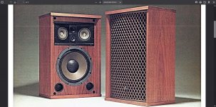
I've been here a long time but more on the reader side, today a decided to share the new portable speaker I've been working.

First, this probably the 5th portable speaker I've built, so its a culmination of everything I've learned on previous build plus a few bookshelf and sub-woofers.

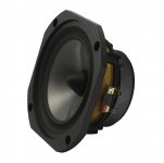
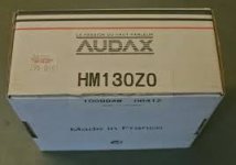
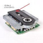
The drivers will be the same as my previous box, two 4,5" Eastech mid bass and two Peerless DQ25SC16. No wait, 4 of each, since I will build two almost identical boxes, one for me and one for my father.

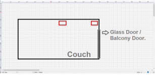
This is what I wanted:
-Smaller than the previous one (10l max vs 21l)
-Play way lower

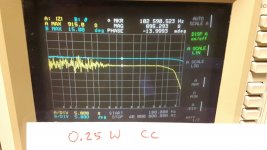
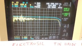
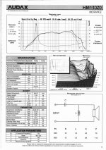
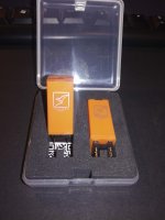
This mid bass was something golden that I found on a electronic stores, bought it what parameters whatsoever. After measuring I knew it would perform well

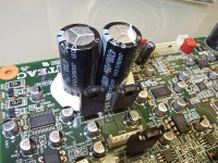
Bellow is an simulation in Hornresp of what I came up. Extension to almost 40 Hz in a 3,5 l enclosure. The way to do that was tunning the passive radiator really low as a mean to keep excursion under control, and them just brute force trough equalization.

Response @ 2pi
An externally hosted image should be here but it was not working when we last tested it.


An externally hosted image should be here but it was not working when we last tested it.


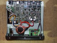
In theory it would work, but I wasn't so sure, so I build a test box to measure and more important, listen. My biggest worry is that the high excursion even at low volumes would distort the rest of the spectrum

An externally hosted image should be here but it was not working when we last tested it.


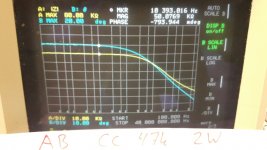
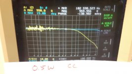
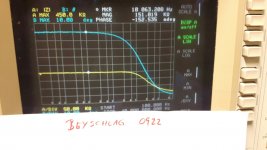
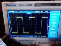
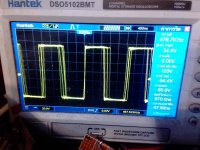
It worked perfectly, I used my Mini DSP to apply the required equalization and took a quick measurement to see what the response looked like, and after that hooked up a tweeter just to listen for a few hours and see if the sound was pleasing.

Near field response of each driver and summed response

An externally hosted image should be here but it was not working when we last tested it.


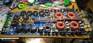
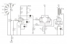
After that what was left to do was finish the box design and design a filter to go with it

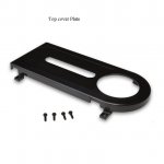
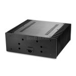
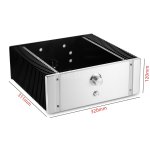
For the box I went with the smallest size that could fit the drivers, the final dimensions is 401x148x183mm, all made to be CNC cut

An externally hosted image should be here but it was not working when we last tested it.


An externally hosted image should be here but it was not working when we last tested it.


An externally hosted image should be here but it was not working when we last tested it.


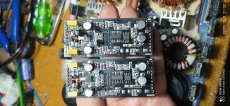
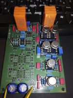
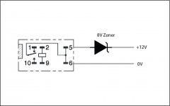
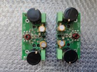
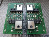
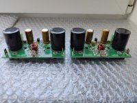
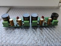
For the filter I have a PEQ, a 4th order butterworth low pass and a BSC, all adjustable from outside the box by just removing the back portion of the cloth. The PCB should arrive soon

An externally hosted image should be here but it was not working when we last tested it.


An externally hosted image should be here but it was not working when we last tested it.


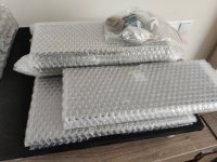
Today I received all CNC cut wood, my plan is to assemble the box this week and take some measurements to start working on the crossover

An externally hosted image should be here but it was not working when we last tested it.

Sony sscs5 or Dayton Audio in India.

If you like hard core tonality but don't care much about bass , it is hard to beat Sony sscs5 in price.

I cannot find any retailer selling it in India.
Few years ago Sony use to sell stuff in India , literally everything in their Hi-Fi range but well it seems over.

Another thing i want to get is Dayton Audio B652 AIR but their again no body selling it in India.

I found a site called Avstore.in selling polk audio , but i am worried if this site is legit.

Donation / contribution methods?

Jason:

I'm a contributing member of diyAudio and am wrapping up a group buy for Mark Johnson's VRDN power supply circuit. I'd like to contribute most of the profit from the group buy to diyAudio, honoring Mark for his contribution to the community and the group buy participants for, you know, participating. I don't want anything for making the donation. Is there a way a non-benefitting donation can be made to diyAudio?

Regards,
Scott

SSE what Cartridge for turntable

Ok I'm still working on my SSE saving money for Trannys, (edcor power, XPWR222, Edcor Opt's, GXSE15-5K), I have Tung Sol reissue EL34B's to start with. Just picked up a Dual 1019 TT, I'm in process of cleaning and lubing, and trying to decide on a Cartridge looking @ Ortofon 2M red, Grado Blue3, or Nagaoka MP-110, I've built a Hagerman Bugle 2 MM. any opinions on Carts?

Bell 2440 stereo and the hard to come by 7189a output tubes. Best way to proceed?

I stumbled upon a bell 2440. No tubes were included and my jaw dropped when I saw the price of those output tubes. I'm curious what some of you think would be the best way to approach this restoration.

There was a great thread here on adding individual bias control but that may be out of my area of expertise. I feel like the easiest method is buying a matched quad of Russian 6p14p-k tubes, which I've heard conflicting reports on whether or not they can handle the 400v.

I would be very interested in trying the bias approach if that meant that I could use any el84 since they are much cheaper, and with individual biasing they wouldn't need to be matched correct?

I feel like this amp is worth the work needed, I just feel a little overwhelmed on how to proceed!

Deliberately misleading specifications.

Not audio.

I sell quite a bit of electronics on ebay and also sell PCBCAD software.

I had trouble competing with other sellers.
So started looking for more unique less easy to make things to sell.

I came across a model railway DCC (digital command control) shuttle controller.
It shuttles a model loco between two points on a track.
To control it you send digital FM signals down a pair of rails.
I managed to get the loco to go back and forth and change speed ok.
Managed to sell a few at a profit (for a change!)

Next project was a DCC encoder controller.
This can not only change speed and direction but also some of the loco configurations like acceleration speed, deceleration speed and loco address.

Most of this was ok except I couldn't change loco address.

So I read up the NMRA (national model railways association) spec for DCC.
As far as I could see I was sending right commands but no joy.

I looked far and wide on the internet for specs and other peoples attempts at it but couldnt get it working.

So in the end joined MERG (model electronic railway group)
After a few threads on there someone eventually pointed me to a pdf file that described how to do it.

It seems you cant just send the change loco address command.
You have to do a a number of resets to the loco to put it in service mode.
You then have to reset two other config variables in the loco.
Only then can you send new loco address command.

I must have messed about for 2 weeks trying to get this working.
The illusive spec was hidden in the vastness of the internet.

Input Module BTM-S

Anybody know what a Peavey Input Module BTM-S is good for?They come in MMA-875t amps , have 3 screws on them 1,2,3, and when I put a FM radio earphone signal on pins 2,3 had hardly any output at all. Pin 1,2 is worse. When I put the signal in the one AUX-IN module with 2 RCA jacks, the amp output was normal volume. That's my FM radio.
I don't have a selection of parts amps & cables anymore, the burglar carried every one off in September in 3 SUV loads. I just received a $30 with freight MMA-800 mixer with 8 AUX-2 modules, and every one is missing the screw adapter that goes over the pins. So I'd like to use the other MMA-875t amp I got for $45 (with freight) with only BTM-s modules to amplify the headphone output of the PC to the $2 speaker I bought at SalvationArmy resale today, but all I have for stereo 1/8" phone plug is wires cut from a dead headphone. No 1/8" to dual RCA plug adapters were at SA. I can buy any cable or adapter I want for $50 minimum from newark or digikey, right after I pay the county tax, state tax, and 2 annual insurance premiums all of which are due between 11/10 and 12/15. So is there any way I can listen to streaming music from WCPE this week that WUOL-FM is talking continuously, without the sound coming at 1/2 watt from a 1.5 cm speaker in the back of the PC? Which is horrid, but not as bad as all that begging on the FM station I already paid my annual subscription to.

cold solder paste to repair panel sl3

good afternoon, does anyone know if cold solder paste can be used to replace graphite tape on martin logan electrostatic panels?
I have one that sounds looser than the other and once cleaned it remains the same, I had thought of highlighting with cold solder paste and incidentally opening a connection line on the other side of the panel to improve conductivity.
Thank you

Help debug 300B amp, thin sound, low volume

Hi all,

Finally finished my long term project, the Glasshouse 300BSE amp.
I fired it up, checked all the voltages and played some music for the first time.
The issue I have is a very thin sound (no mid/low frequencies) at very low volumes. I'm guessing max volume is 60-70dB

I've attached the schematic and all the voltages check out to a few % except on the anode of V1 & V2 (the EF86). That should be 175V and measures 212V.

The original amp uses a 2.5K output transformer, I'm using a 3.3K OPT.

No noise, pops etc. when turning on and playing. Only thing I thought was weird is I measure 0.2 ohms between the OPT common and 4/8 ohm tabs (while turned off). Is that normal?

Any help is appreciated

Cheers

Attachments

  • 300bse-schematic.png
    300bse-schematic.png
    292.3 KB · Views: 435

FS: USB scopes

I have a couple of USB PC oscilloscopes up for grabs.
One is 10 mega samples/second the other is 20 mega samples/second.
These were prototypes so just looking to get back cost of components.
Time base max is 10uS for 20 meg part and 20uS for 10 meg part.
Bandwidth is around 3MHz so good enough for audio work.
Comes with PC software that includes analogue display plus FFT.
Usual +/- 3.3 volts max input but it can be vastly increased with x10 and x100 probes.
10 meg = £20 plus p+p
20 meg = £25 plus p+p
p+p is £4-20 to UK and £14 to rest of world.

KODAK-Digital-Still-Camera.jpg

KODAK-Digital-Still-Camera.jpg

Modern internaled radio for 1956 Porsche

Hi all. I have a client (I do construction) who is looking to rebuild his 1956 Porsche 356. He's wanting to find an original radio, he's doing an original rebuild, but he would like the radio to have modern internals. I could do all of that, but finding the original radio, that's not so easy. I usually deal with vacuum tube audio, and I know how my fellow enthusiasts like to pile parts just like I do. So I thought maybe one of y'all car audio guys would be similar. I'm sure the exact year isn't crucial, any old German radio that would have been near that year. I'm not familiar with mobile audio beyond subs/enclosures/amps so I'm not sure if DIN was even a thing, and if it was, whether it applies to German cars. But I'm sure plenty of you do know that info. I'm hoping someone will know, and someone will have a radio that would fit at least. This would be a really fun project to put up here, rebuilding it.

Thanks much everyone. I'm looking forward to this

Loren

Looks to me like a great deal on RCA plugs if you're building your own interconnects

Hello all,

Just found these online. I have no affiliation with the company in any way. Was just looking for RCA plugs because I want to make some of my own interconnects.

Some of the company's other plugs get 4.5 stars out of 5 on Amazon (and some of the low reviews are ridiculous...like 1 star because the person didn't realize you had to solder the wire to them.)

Anyway, I don't know how long it will last but at around $9 (or less if you buy several) it's the best buy I found on what appear to be fairly high quality RCAs.

At the time of this posting, the price is $9.99 for a 4-pack (2 with red markings and 2 with black markings.) Price drops to $8.49 if you buy 3-5, and drops further if you buy more than that. Shipping is free and there was no tax. So I bought six 4-packs of what seem to be good quality RCAs for just under $48.

GLS Audio 24K Gold Locking RCA Plugs and Connectors - 4 Pack

Pioneer Integrated Amplifier A-757 (A757) and A-757 MK-II - what differences ?

Service Manual of Pioneer's predecessor of A-757 MK-II version is here:
PIONEER A-757 SM Service Manual download, schematics, eeprom, repair info for electronics experts
(Pioneer Class-I, idle current servo "PA0016" in use - go to
https://www.diyaudio.com/forums/solid-state/202684-class-siblings-17.html#post2864279
and from post #2321 under
Bob Cordell's Power amplifier book)

But I don't find the service manual of the MK-I version (model name only "A-757").
Who can upload this ? And where is the main difference in the internal topology ?
Thank you very much for advices.
Now the service manual is here:
Pioneer A-757 Stereo Integrated Amplifier Manual | HiFi Engine

Attachments

  • Pioneer A757-I.jpg
    Pioneer A757-I.jpg
    69.4 KB · Views: 1,316
  • Pioneer A757-II.jpg
    Pioneer A757-II.jpg
    148.8 KB · Views: 1,531
  • Pioneer A757-III.jpg
    Pioneer A757-III.jpg
    41 KB · Views: 1,721
  • Pioneer A757 MK-II-I.jpg
    Pioneer A757 MK-II-I.jpg
    558 KB · Views: 2,825
  • Pioneer_A-757_Mark_II_-3.jpg
    Pioneer_A-757_Mark_II_-3.jpg
    290.9 KB · Views: 1,470
  • Pioneer-A-757-Mark-II-Vollverstarker-Bolide-Schwarz.jpg
    Pioneer-A-757-Mark-II-Vollverstarker-Bolide-Schwarz.jpg
    169.5 KB · Views: 913

Aragon 2005 THX amp bias how to?

So today I learned that amp bias was even a thing. I can see I have pots on my amp, what can be gained by properly tweaking and calibrating the pots, and is this something needed to be checked every few years on an amp that's a few years old? And how exactly would I do this?

Aragon 2005 THX Ultra 2 Class A/B amp specs:

DESIGN 5-ch THX Ultra2 Amplifier

POWER OUPUT 200 watts/ch into 8 ohms at less than 0.03%

THD (20Hz-20kHz - 3 channels driven)

POWER OUTPUT 300 watts/ch into 4 ohms at less than 0.05% THD

FREQUENCY RESPONSE 20Hz-20kHz +0/-0.1dB 10Hz-100kHz +0/-0.5dB

TIM/DIM DISTORTION 0.00%

S/N RATIO 106dB A-weighted

DAMPING FACTOR 500 (8 ohms - 50Hz)

INPUT SENSITIVITY 100mV-1W / 1.42V-200W

INPUT IMPEDANCE 20k ohms

Aragon - 2005 (Klipsch)

All pictures here Aragon 2005 THX 5 channel amp - Album on Imgur

An externally hosted image should be here but it was not working when we last tested it.

An externally hosted image should be here but it was not working when we last tested it.

An externally hosted image should be here but it was not working when we last tested it.

Making a relay de-energize more quickly

I'm adding a shunting relay to mute the output of a tube preamp. The issue is mostly at power down, I get a big bump on the output. I've read all the threads on this, but my question is a little different.

My chassis is already extremely tight, so I have room for a mini relay and maybe a resistor and diode that's it. I don't wish to create any elaborate circuits. I'm choosing only to address the turn-off bump at this time because it's most egregious. My power amp has a delay turn/on function when using a trigger, so any noise coming from the preamp associated with the slow B+ climb are solved enough for now. Turning off the amp via the trigger does not happen fast enough to avoid the turn-off bump from the preamp however.

I have a small 12VDC power supply already in the chassis for a 12V trigger, and LEDs and such, so I can use this to control the relay. Because the power-off bump happens so quickly after I turn off the amp (or physically unplug it), I need the relay to de-energize very quickly, before the B+ collapses, in order to shunt via the NC contact.

I'm thinking to use this relay. Like most relays, it energizes at 80% of rated V, and de-energizes at 10% which is way down at 1.2V.

QUESTION
Can I make the relay de-energize more quickly and at a higher V, like lets say 8V, by using a zener somehow? Will the attached sketch work? I may totally be misunderstanding how zeners actually work, so pardon if this is a silly question. I'm a little unclear if the zener conducts the full voltage from cathode to anode when reverse biased, or if it drops the full voltage equivalent to the breakdown voltage.

Attachments

  • zenerIdea.jpg
    zenerIdea.jpg
    49.5 KB · Views: 385

Sony CFD-ZW755 cd play problem

Hi Forum,

I have a Sony CFD-ZW755 RADIO/CD/TAPE player I have had for 10 plus years and the cd player recently died. From my research it sounds like the optical pick-up on the cd mechanism has failed. I found the service manual and it says the cd mechanism I have is a KSM-213RDM because my serial number is greater than 0560201. Before that point the unit used a KSM-213CDM. My problem is I can't find a KSM-213RDM available but I have found the KSM-213CDM.

Does anyone know if these two cd mechanisms are interchangeable or is there some other cd mechanism that will work for the KSM-213RDM?

The reason I want to try to repair my current machine is because I have not been able to find anything new out there that has the size and power of my current boombox with radio/cd/tape features.

I'm kinda stuck and don't know what else to do so any feedback would be super appreciated.
Thanks all.
Best,
-Tim

FS Like new pair JBL 2453H-SL compression drivers

SOLD SOLD SOLD FS Like new pair JBL 2453H-SL compression drivers

Hello, I'm parting out systems to make room for new projects.

I got these from Speaker Exchange new back in June 2020. Cosmetically and functionally 10/10. $600 shipped in original boxes within CONUS. I'll ship internationally at your cost. Thanks for looking!

I also have a pair of 2384 horns that we can talk about but shipping on those is pretty expensive. PM me to discuss a fair price for the horns.

Pair of First One v1.2 amplifier modules

Selling used FO v1.2 modules. They are set for 45V, so Hypex SMPS1200A180 would be the recommended power supply.

More information in this thread: First One - mosfet amplifier module

Asking price: 130 EUR + shipping from Latvia.

Attachments

  • 1594983367787-sm.jpg
    1594983367787-sm.jpg
    732.1 KB · Views: 234
  • 1594983367851-sm.jpg
    1594983367851-sm.jpg
    565.8 KB · Views: 222
  • 1594983367896-sm.jpg
    1594983367896-sm.jpg
    537 KB · Views: 222
  • 1594983367940-sm.jpg
    1594983367940-sm.jpg
    529.3 KB · Views: 221

New full aluminium amplifier case including heat sinks

Selling here new unpacked amplifier case with heatsinks. I am using another 3 for my active 3-way system with a pair of First One amplifiers and Hypex SMPS in each case (see picture attached). I wanted to make a 4-way system, but decided to stay with a 3-way.
The case is very solid and high quality. Buttons, power cord socket, screws and rubber feet included.

External dimensions: 320x311x120mm
Internal dimensions:300x220x112mm

Bought few months ago here: Leistungsverstarker Gehause Aluminum DIY Metal Case for Power Amplifier Chassis | eBay

My asking price: 145 EUR + shipping from Latvia

Attachments

  • 1602330196182-sm.jpg
    1602330196182-sm.jpg
    588.6 KB · Views: 444
  • s-l1600 (1).jpg
    s-l1600 (1).jpg
    70.5 KB · Views: 438
  • s-l1600.jpg
    s-l1600.jpg
    84.9 KB · Views: 448
  • P1240068 (1).JPG
    P1240068 (1).JPG
    692.5 KB · Views: 446
Projects by fanatics, for fanatics
Get answers and advice for everyone wanting to learn the art of audio.
Join the Community
507,743
Members
7,886,382
Messages

Filter

Forum Statistics

Threads
406,148
Messages
7,886,382
Members
507,743
Latest member
Fitodiod