I am looking at building a SET amp with some sort of voltage regulator as the last stage. I have read that a good voltage regulator can provide low impedance over the entire frequency range vs a capacitor.
I have been looking at using a simple shunt regulator with a CCS and a couple VR tubes in series. However I have read that while VR tubes have negative DC resistance, they do tend to have higher dynamic impedance.
Can someone confirm if this is true, and if so, does anyone know exactly how much impedance they might have compared to a ~100uf capacitor?
Ultimately I am trying to find a voltage regulator that has a consistently low impedance that is independent of frequency.
1. OD3 150V gas regulator: The voltage changes 4V as the current changes from 5 to 40 mA.
4V change / 35mA change = 114.3 Ohms of dynamic resistance (not negative resistance).
The 114.3 Ohms is relatively constant over the complete audio range (DC to > 20kHz).
The only negative resistance of a gas voltage regulator is before it first ignites, ignites, (at a voltage much higher than the regulation voltage, and then it ignites and draws current at the regulated voltage).
High voltage, low current; lower voltage, high current = negative resistance.
That negative resistance that occurs between non ignited and ignited states is why a capacitor connected across the gas regulator tube will oscillate (relaxation oscillator).
2. Capacitive Reactance, Xc = 1/(2 x pi x f x C). For 100uF:
At 20 Hz, Xc = 1/(2 x 3.14 x 20 x 100e-6) = 79.6 Ohms.
At 10 Hz, Xc = 159.2 Ohms.
At 5 Hz, Xc = 318 Ohms.
3. Show us your schematic, please.
A gas voltage regulator is not a capacitor.
Gas voltage regulators regulate voltage.
Capacitors Store Charge (which can supply current to the load).
4. Want to regulate a screen voltage, OK, a gas regulator is fine.
Want to power a triode output tube plate current, a gas regulator is Not OK.
Last edited:
As always thank you for the reply.
Very interesting. I had been reading this whole time that VR tubes have negative resistance and that you need to be careful not to form and oscillator, so I was thinking that it displayed negative resistance during its operation.
As such I thought the VR tubes dynamic impedance was MUCH more complicated. But it makes sense now.
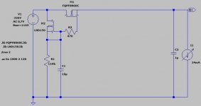
Below is the power section of the schematic. I am out and about, so I scribbled this in the car. I do realize I am missing a capacitor around the voltage regulator tube. That was not intentional.
Let me know what you think. If I am just barking up the wrong tree, let me know if there are any decent alternatives you would recommend.
Very interesting. I had been reading this whole time that VR tubes have negative resistance and that you need to be careful not to form and oscillator, so I was thinking that it displayed negative resistance during its operation.
As such I thought the VR tubes dynamic impedance was MUCH more complicated. But it makes sense now.
Below is the power section of the schematic. I am out and about, so I scribbled this in the car. I do realize I am missing a capacitor around the voltage regulator tube. That was not intentional.
Let me know what you think. If I am just barking up the wrong tree, let me know if there are any decent alternatives you would recommend.
An externally hosted image should be here but it was not working when we last tested it.
Last edited:
I'd recommend reading the datasheets!
Its a complex thing a gas discharge tube, with various modes of operation, some of which are eratic (transitions between glow- and arc-discharge for instance). "Negative resistance" isn't really an adequate description, there is hysteresis in striking, then you want it to stay in a state where the whole electrode is covered by glow discharge (enough current flowing), but never breaking through to arc discharge (too much current). Too little current will cause eratic operation, too much will cause eratic operation and damage, too little series resistance in the supply to the tube will cause problems, too much capacitance in parallel will cause problems. too little capacitance and it will be too noisy.
Basically follow the recommendation of the datasheet for the part in question, it will likely tell you just how to use it without problems.
http://www.junkbox.com/electronics/sheets/GE_Glow_Tubes_ETI-176.pdf
(Basically its just a large neon bulb (sometimes a different gas is used)).
Last edited:
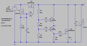
Just got home and it seems like my image nuked itself.
Lets see if this works.
Imgur: The magic of the Internet
Lets see if this works.
Imgur: The magic of the Internet
Consider a VR tube to be like a zener. Good as a reference but not for high power.
You can however pass one with a FET and get a stable reference with more current capability. This becomes a voltage regulator.
You can however pass one with a FET and get a stable reference with more current capability. This becomes a voltage regulator.
...low impedance over the entire frequency range vs a capacitor......
How "high Z" is a modern capacitor?
1,000uFd is not expensive, even at 450V, in SET economics. 1,000uFd is 10 Ohms at the bottom of the audio band. Your amplifier impedances are likely 500 times higher than that. The cap change of Z from 10r to sub-r in treble is really insignificant, swamped by >100r of DCR in everything else.
You are worshiping a principle into a pickle. Slap a fat cap on the end, boom, done.
You are worshiping a principle into a pickle. Slap a fat cap on the end, boom, done.
Damn - I just found me a new hero.
May be true, in some circumstances, but it´s just a generic phrase or idea.I have read that a good voltage regulator can provide low impedance over the entire frequency range vs a capacitor.
Bu then you have to "put some numbers into it" and then it achieves real meaning.
What PRR did ....... and then it does not hold much weight, at least in this particular situation.
How "high Z" is a modern capacitor?
1,000uFd is not expensive, even at 450V, in SET economics. 1,000uFd is 10 Ohms at the bottom of the audio band. Your amplifier impedances are likely 500 times higher than that. The cap change of Z from 10r to sub-r in treble is really insignificant, swamped by >100r of DCR in everything else.
You are worshiping a principle into a pickle. Slap a fat cap on the end, boom, done.
I thought the problem with big caps is that they take a longer time to fill back up after a large transient depletes them. You end up needing impossibly low amounts of DCR in the PSU in order for a capacitor of that size to recover quickly.
I have read quite a few articles preaching to that same pickle. (btw, you gotta put that quote in your signature or something. That is just plain gold right there).
https://www.pearl-hifi.com/06_Lit_A...apers/Loesch_Thorsten/Thorsten_on_SE_Amps.pdf
BTW, I am not dead set on using a regulator. Im just trying to get as close as humanly possible to an ideal power supply. Im building myself a new SET amp, and I would like it to be as perfect as possible so that I can call it done. So many of my other amps get built and then rebuilt and rebuilt and rebuilt as I learn about new topology and design philosophy. I just want 1 amplifier that I can truly call "finished", so I am trying to pull out all the stops.
Last edited:
When you want to go all out, regulation is the way to go. Take in account indirect heated tubes too when your mains is unstable. Be aware of the burdon of dissipation in your build, as all heat sources add up. A perforated deck plate might be a good way to go. I've built some copper chassis in the past and for cooling it's bare to none. There are excellent regulator designs around that come with a clear instruction. Which finals are you planning?
When you want to go all out, regulation is the way to go. Take in account indirect heated tubes too when your mains is unstable. Be aware of the burdon of dissipation in your build, as all heat sources add up. A perforated deck plate might be a good way to go. I've built some copper chassis in the past and for cooling it's bare to none. There are excellent regulator designs around that come with a clear instruction. Which finals are you planning?
This first amp will be a prototype of a circuit I am working on which will use a 3a5 and a 45 and will be a headphone amp.
The final will be a 417a and a 300b.
this would be bad for endstage.Just got home and it seems like my image nuked itself.
Lets see if this works.
Imgur: The magic of the Internet
it represents too high resistance, ideal powersupply is zero ohms.(literally a big capacitor)
but if u put big cap to vr (neon tubes) they start oscillating or self damage.
if a tube needs low voltage; buy correct trafo/supply. when you regulate down so big voltages, any circuit will generate lots of heat/inefficiencies.

I thought the problem with big caps is that they take a longer time to fill back up after a large transient depletes them.....
Sure. But what is a "large transient" in a class A (SE) amp which should work at nearly constant current?
If you pull a big + peak, it is likely followed/preceded by a large - peak, and they tend to cancel. (Yes, turning-off the tube kicks some amount of energy back into the supply cap.)
And how close together do transients happen? Yes, highly compressed brick-wall processed pop/dance music has peaks like a picket fence. Which plays dandy on the transistor amps it was produced for. But that's not why you own a SET amp.
And as said: Put Numbers On It! You can always, if you really need to, re-fill a big bucket fast with a big hose (fat PT).
Or Try It! Put a sensitive volt meter on B+ and play the amp. When I worked class B amps HARD on test-tone load I could droop B+ 15%. When I played them HARD for concerts in the park B+ rarely dripped 5%, and only because the crowd tolerated a little distortion. A fussier crowd, or a less suckage amplifier mode, I would not expect to see any dip.
Currents with SET HT are low (hundred mA range typically). When you observe the heater / filament current, things are a little different on loud passages. It's no luxury to have double the LV output current available. Also keep the internal resistance low and put some fat caps in the heater supply.
A big cap can take longer to recover from a 'transient'.
A big cap is less bothered by a transient, so it has less to recover.
As always in audio, there are two schools of thought:
1. make caps as big as possible, and don't worry about all the narrow spikes you might be injecting into grounds
2. make caps as small as possible, and explain the supply sag causing gain pumping as being extra dynamics
There is also the middle path of good engineering, but that requires use of numbers.
Be sure to make the secondary, rectifier, and first cap have its own local loop.
Do not connect the center tap (or bridge negative out) and first cap negative to your central star ground.
All the transient current needs to be in the local loop. Sometimes even the second cap negative needs to be in this local loop too.
Make sure to position those first parts near each other, so the wires can be short.
Keeping these transient currents out of the star ground does wonders for reducing hum.
After you have created the local loops, Then connect the negative of that cap to the star ground.
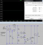
The success with a big cap to stabilize supply output voltage depends on the impedance of the supply. My example here might be extraordinary but I happen to have it hand. The raw supply has no less than 1165 ohm impedance, a huge size cap does close to nothing here. A basic serial regulator puts that back to 76 ohm, where a shunt regulator arrives at 14 ohm. Any size capacitor after the regulator has no bearing on PS output impedance; I varied the load between 30mA and 34mA. Again, it's a situation one has not to deal with often but it shows to a certain extend the possible outcome.Sure. But what is a "large transient" in a class A (SE) amp which should work at nearly constant current?
If you pull a big + peak, it is likely followed/preceded by a large - peak, and they tend to cancel. (Yes, turning-off the tube kicks some amount of energy back into the supply cap.)
And how close together do transients happen? Yes, highly compressed brick-wall processed pop/dance music has peaks like a picket fence. Which plays dandy on the transistor amps it was produced for. But that's not why you own a SET amp.
And as said: Put Numbers On It! You can always, if you really need to, re-fill a big bucket fast with a big hose (fat PT).
Or Try It! Put a sensitive volt meter on B+ and play the amp.
Attachments
a huge size cap does close to nothing here. A
You are analyzing at DC (at 0 Hz) now, but the signal voltage is AC. For example a 100uF capacitor at the output of the regulator create some 16 ohms output impedance at 100 Hz.
- Home
- Amplifiers
- Tubes / Valves
- Need help trying to understand voltage regulators.