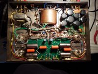
I have this st70 and need help adjusting the bias... it has 6 pot adjustments, I think the four outer ones are for the output tubes but not sure about the two center ones?
Also I have two sets of output tubes gold lion kt66 and EL34, what do I set the bias voltage to? Is it the same for both sets of tubes? And what are the center pots for? How do you adjust those and to what voltage?
Any help would be appreciated.... I’ll try to post pictures of the amp inside and out so you can see what was done to it...
I’m new to this tube amp stuff.
Attachments

Any chance of obtaining info about the modified driver board and the rest of it? A schematic would certainly be helpful.
With tubes, you typically are setting a current and the circuit provides a voltage reading proportional to that current. So the first step is to find that measurement point. You cant just set each tube to "-20V", because the current could be very different at that voltage for each tube - and tube type.
There must be some information available from whoever made the mod, at least where the bias measurement point is and what to set that to. I assume that's lost and that's why you're asking here -
For 6CA7/EL-34 output tubes, adjust each of the four bias pots for 50mA cathode current per tube,
which would be 0.5VDC across each of the 10R resistors. These voltages are wired to the two
octal front panel test sockets (each red wire). Connect the negative voltmeter lead to the chassis.
If the reading goes down when you turn the pot up, you probably are measuring at the wrong
voltage test point of the two wires (the other tube of the pair will tend to go down when turning up).
Repeat the adjustments until all four of the tubes read 0.5VDC after a 30 minute warm up.
It would be ok to use the same bias setting for 6L6 tubes as well.
The other two pots are likely to be for AC balance, so avoid changing those without test equipment.
Last edited:
I bought this amp the way it is, I’m not sure where the driver board is from, I’m hoping someone will recognize it and have some information
For 6CA7/EL-34 output tubes, adjust each of the four bias pots for 50mA cathode current,
which would be 0.5VDC across each of the 10R resistors. The other two pots are likely to be
for AC balance, so avoid changing those without test equipment. It would be ok to use the
same bias setting for 6L6 tubes as well.
Thanks for the info....
For a starter , this no not a dynaco st-70. It might have been one once.I have this st70 and need help adjusting the bias... it has 6 pot adjustments, I think the four outer ones are for the output tubes but not sure about the two center ones?
Also I have two sets of output tubes gold lion kt66 and EL34, what do I set the bias voltage to? Is it the same for both sets of tubes? And what are the center pots for? How do you adjust those and to what voltage?
Any help would be appreciated.... I’ll try to post pictures of the amp inside and out so you can see what was done to it...
I’m new to this tube amp stuff.
It could be an early vta70 board , in that case you could get schematics from
roy mottram.
If not, your best chance is to get the dynaco manual and get the missing parts from dynakitparts.com and rebuild as a dynaco st70
The amp is fine as it is, better than stock for sure. The schematic is not necessary for getting it working,
but probably is floating around. I would resolder all the tube socket pins, (take the tubes out first).
The two switches are likely for triode/pentode operation. NEVER switch them while the amp is powered on.
but probably is floating around. I would resolder all the tube socket pins, (take the tubes out first).
The two switches are likely for triode/pentode operation. NEVER switch them while the amp is powered on.
Last edited:
The amp is fine as it is, better than stock for sure. The schematic is not necessary for getting it working,
but probably is floating around. I would resolder all the tube socket pins, (take the tubes out first).
The two switches are likely for triode/pentode operation. NEVER switch them while the amp is powered on.
Thanks good to know...
Well,
I see that the original 2 bias pots have been removed, and replaced by toggle switches.
I do Not see any bias pots (oh, I see 6 pots on top of the PCB.
Actually, the original Dyna Stereo 70 used only 1 pot per channel (it relied on having a pair of EL34 tubes that were perfectly matched at the exact same plate voltage and screen voltage that the Dyna Stereo applied to those plates and screens. With perfectly matched tubes, the current was adjusted to 100mA, 50mA per tube.
I recommend modifying the amp for just a little less output power, but for a little more finesse.
Use Individual Self Bias RC networks. A resistor and bypass cap for Each tube (4 tubes, 4 resistors, 4 bypass caps).
Most tubes will now match properly, even though they are not Perfect matches.
And, you can easily read the bias voltage, and calculate the currents, and see how well they match, with new tubes, and as the tubes age.
Also, they will match just as well when the Mains Power voltage goes up and down (my mains go from 117V to 123V, and the B+ changes by the line voltage to B+ multiplier factor, so B+ changes a Lot, including voltage on the Screens). The screen voltage change has much more effect on current than the plate voltage change. Self Bias does a pretty good job of evening out the current changes versus power mains voltage changes.
Push Pull output transformers require matched plate currents if you want the best low distortion of low frequencies, as has been repeatedly written on many threads on this forum,
Global negative feedback can not correct for un-matched plate currents, it only makes the saturation distortion of low frequencies Worse!
The above are just my opinion (and just my experience with self bias).
Your Mileage May Vary (try it for yourself and see).
Last edited:
- Home
- Amplifiers
- Tubes / Valves
- Need help with dynaco st70