Cambridge A1 MK1 amplifier - main power fuse blows
- By Crimsontide
- Solid State
- 6 Replies
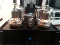
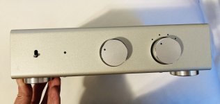
I have a Cambridge A1 Mk 1, the one with the volume control at the far right, and a few days ago the power light went off as it was in use at low volume , and sound stopped completely.
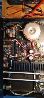
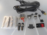
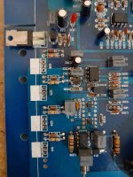
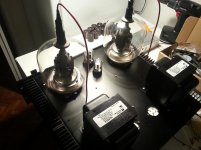
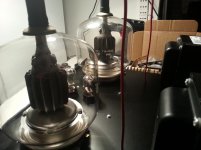
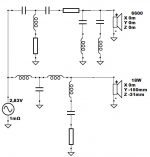
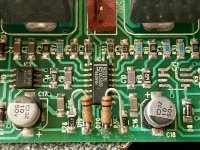
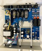
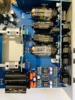
I disconnected the amp from the mains, took the lid off and found that the fuse on the power supply switch board (top left in photo) was blown. A new fuse T2A 250 V blew out immediately the amp was switched on. I then disconnected the amp from the system and carried some continuity/resistance checks. I noted that the rectifier circuit is actually built into the main power amplifier board and I found that the secondary output power leads from the transformer to the rectifier bridge (purple and yellow in the photo) were both zero resistance to earth, even when I disconnected the two fuses. As I read the layout, those wires should not be earthing, as they are feeding power to the rectifier circuit which then feeds the two amplifier circuits.
The red and white wires from the secondary windings are earthed as they are connected to the black earthing wire at the “rail” which is between the two large smoothing capacitors , and the "rail" is achieved by a large trail of solder under the circuit board.
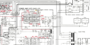
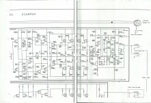
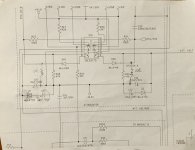
As I don’t have a schematic, I’m basing my knowledge on a circuit diagram of a Crimson Electrik CE170 kit from 1980 (no IC power transistors), and application of the basic arrangement to a few other amps including a NAD3070.
My conclusion is that the secondary windings of the transformer have short-circuited to earth. Can anyone confirm this?
I disconnected the amp from the mains, took the lid off and found that the fuse on the power supply switch board (top left in photo) was blown. A new fuse T2A 250 V blew out immediately the amp was switched on. I then disconnected the amp from the system and carried some continuity/resistance checks. I noted that the rectifier circuit is actually built into the main power amplifier board and I found that the secondary output power leads from the transformer to the rectifier bridge (purple and yellow in the photo) were both zero resistance to earth, even when I disconnected the two fuses. As I read the layout, those wires should not be earthing, as they are feeding power to the rectifier circuit which then feeds the two amplifier circuits.
The red and white wires from the secondary windings are earthed as they are connected to the black earthing wire at the “rail” which is between the two large smoothing capacitors , and the "rail" is achieved by a large trail of solder under the circuit board.
As I don’t have a schematic, I’m basing my knowledge on a circuit diagram of a Crimson Electrik CE170 kit from 1980 (no IC power transistors), and application of the basic arrangement to a few other amps including a NAD3070.
My conclusion is that the secondary windings of the transformer have short-circuited to earth. Can anyone confirm this?


![PXL_20230919_214629906[1].jpg](/community/data/attachments/1122/1122935-f6aefa9d067d139741fde019d11737fe.jpg?hash=9q76nQZ9E5)