Simplest possible 1-transistor power amplifier with THD <1%
The challenge was to build a simplest possible amplifier that would be still usable. With wide frequency range, flat frequency response, reasonably low output impedance and reasonably low, inaudible THD. I am offering the result – the necessary functional circuit part has only 1 transistor, 2 resistors and 2 capacitors. 2 more resistors (discharging of coupling capacitors) and 1 supply bypass capacitor were added to the final circuit. The amplifier was designed for fun, as a circuit challenge, but the necessary condition was it must be workable and repeatable.
The circuit is a class A emitter follower with a BJT power transistor. It has voltage gain close to 1x, so it makes no voltage amplification. But it has current gain, thus also power gain, so it is a power amplifier, though with very low power, if we do not want to build it big with large heatsink. Emitter follower has almost 100% series voltage feedback, so it cannot be called “no-feedback” amplifier. Such qualification would be misleading. Due to this strong negative feedback the emitter follower has quite low output impedance, between 0.1 – 1 ohm, depending on the transistor used and also on signal source output impedance. The drawback of BJT follower is quite low input impedance, for load 4 – 16 ohm and transistor h21E about 100, we can count with input impedance 300 – 600 ohm approx.
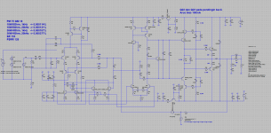
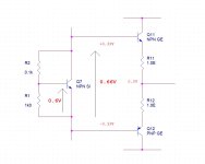
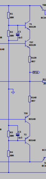
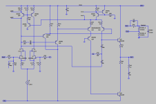
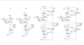
The real circuit
Erratum: C2 = 6800 uF
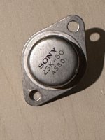
C1 is an input coupling capacitor. R2 is a base bias resistor that sets the idle current of Q1 transistor. Q1 is PNP Sanken 2SA1102 transistor, just for the reason I had them in stock and they fit into my heatsink used for the amplifier. NPN transistor can be used as well in case that all electrolytic capacitors would be reversed in polarity. R4 is an emitter resistor that defines idle current and also limits the maximum current and power into the load. C2 is an output coupling capacitor. R1 and R3 are the discharging resistors to prevent loud clicks when speaker and signal source are connected. C3 is a power supply bypass capacitor. Idle current is set at about 450mA, which makes about 4W idle power loss of Q1 when supplied from 14V. Power supply voltage may be between 12 – 15V. Heatsink used is Fischerelektronik SK409/25, Farnell #4621293.
Edit: C2 = 6800uF
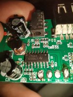
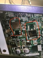
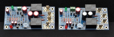
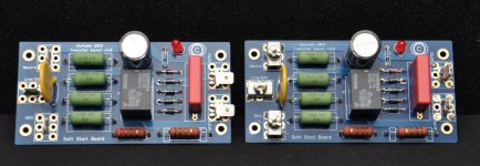
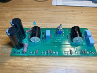
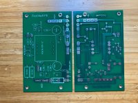
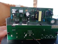
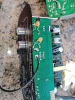
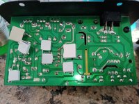
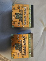
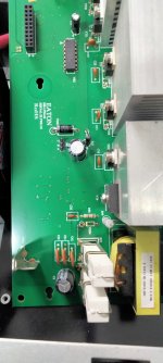
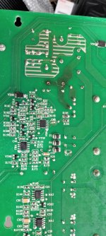
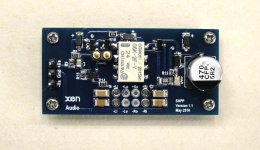
PCB board
The amplifier was built on a 2-layer 87.6 x 60.6 mm FR4 PCB. Produced in China, 5 pcs of PCBs cost 5.00 USD total + shipping cost. Incredible. 2-layer board is only for the reason of reliability, the solder joints would not peel off even if overheated.

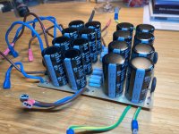
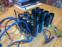
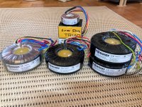
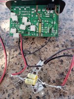
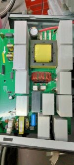
 Power supply
Due to not great power supply ripple rejection of the circuit, a small sealed 12V accumulator is an option. That's how I started to test it. Then I built a traditional bridge rectifier followed by a capacitance multiplier. As the current consumption of the amplifier is almost constant, the capacitance multiplier is a good choice that grossly reduces PSU ripple.
Setting Q1 idle current
Please have a look at schematics above, Fig. 1.
R2*(IE/(Beta + 1)) + VBE + R4*IE = 14V (PSU voltage) (1)
R4 = 10 ohm and we want IE = 0.45A, so R4*IE = 4.5V; VBE = 0.6V; Beta = 50
Calculate R2 from (1) as 1009 ohm, rounded to 1k
So we have R2 = 1k and R4 = 10R.
The capacitors C1 and C2 are chosen not to restrict low frequency response extension.
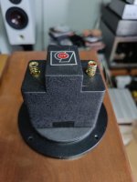
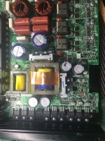
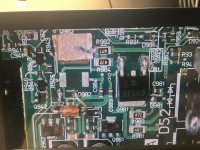
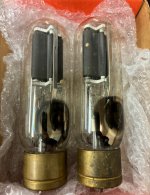
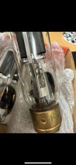
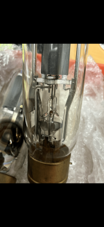
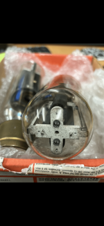
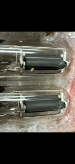
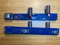
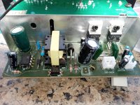
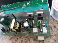
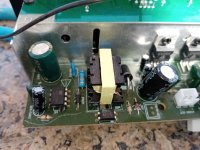
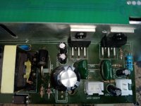
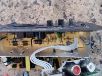
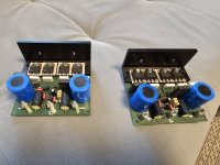
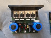
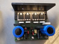
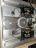
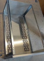
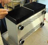
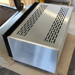
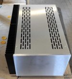
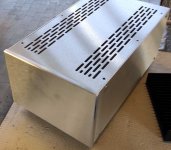
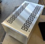
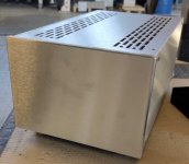
Real amplifier sample
Looks like this:

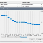
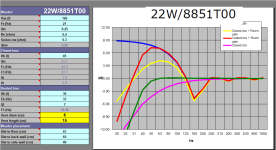
 Parameters and measurements
Input impedance ….. 211 ohm with 10 ohm load
Output impedance ….. 0.32 Ohm with signal source with 50 ohm impedance
Voltage gain ….. 0.976x for 50 ohm source impedance and 10 ohm load (speaker) impedance
Frequency range ….. 20Hz (-0.5dB) – 10MHz, not limited by slew rate
Rise time of step response ….. << 100ns
THD at 1V/10ohm ….. 0.2%
THD vs. level and frequency ….. see plots below
Usable output power for THD < 1% ….. 300mW / 8ohm
Capacitive load ….. up to 2uF
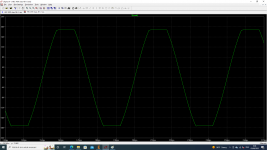
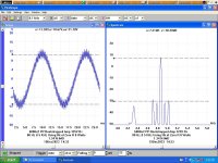
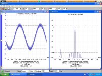
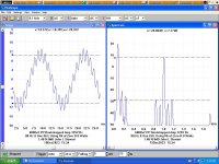
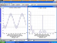
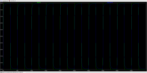
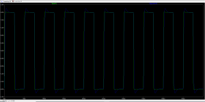
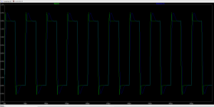
Oscilloscope measurements
10kHz square input and output

Fast rising edge of step response, input and output

1MHz sine, input and output
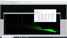
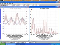
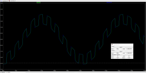
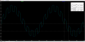
 Distortion measurements
THD vs. frequency

THD vs. level

THD 1kHz

IMD 19+20kHz
 Conclusion
The project was made for fun, to evaluate what is the simplest but still usable 1-transistor amplifier. The circuit has extremely wide bandwidth, very fast transient response, does not care about complex load or shorted output, has still acceptable distortion. But, it has very low power, in case we do not want to build a massive heater, and has low input impedance, that is best to be driven from headphone output of mp3 player, iPad, iPhone etc. Have fun!
_________________________________________________________________
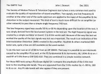
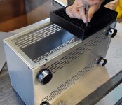
Important - construction notes:
1st sample built has part values according Fig.1., only C2 = 6800 uF. The 2SA1102 used has Beta = 60 and with this transistor idle current is 500 mA.
Today, on Dec 15 I have built a second sample. Interestingly, the 2nd 2SA1102 has Beta = 151 and R2 had to be changed to 1k8, because with 1k the idle current was too high and 10R/5W resistor would be overheated. With R2 = 1k8 and high Beta = 151, the 2nd sample has lower distortion and better measured PSR. It has idle current of 600mA, just at the limit what can be dissipated with the construction shown in the photos above.


![IMG_1628[1].JPG](/community/data/attachments/1159/1159390-76f150a80712e2ee3dde9621f4cbbdfe.jpg?hash=dvFQqAcS4u)
![IMG_1629[1].JPG](/community/data/attachments/1159/1159391-0dbad934dd0466181b270763ef7201a5.jpg?hash=DbrZNN0EZh)
![IMG_1623[1].JPG](/community/data/attachments/1159/1159392-892789788845ed6e898b2eee38368ab5.jpg?hash=iSeJeIhF7W)
![IMG_1631[1].JPG](/community/data/attachments/1159/1159393-ddf90c1ec7e07bebb5b35c908965e26d.jpg?hash=3fkMHsfge-)


