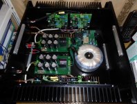
Sinclair (Project 60) Z-30 amplifier and my DIY mods
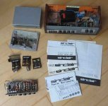
It was in 1969 when Sinclair Project 60 kit appeared on the market in UK and it contained Z-30 amplifier modules, advertised as 25W and 50W peak. It also advertised to be “the world's lowest distortion high fidelity amplifier”
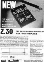
and the news and kit description had soon, only few months later, appeared in our local hi-fi magazine Hudba a Zvuk.
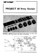
Those days I was building my first amplifiers (with Singleton input stage and awkward circuit topology) and I was excited by Sinclair topology! The differential input stage, CCS VAS load, it was something completely new in the DIY world. However, for us behind the iron curtain, an unobtainium. We had the only chance, to learn and to design and build the thing ourselves.
Several years passed and after I finished my university studies I was still an enthusiastic DIYer and I have returned to the idea to build Z-30. So I took an original schematics
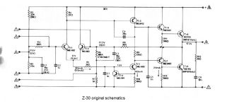
made some small mods like modification to +/- DC power supply (to get rid off the output coupling capacitor) and also changed the transistors, as the originals were not available here. This was probably a good idea, as my power transistors were more robust. And this was the result, in 1980
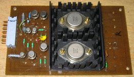
I have chosen a modular concept, with a motherboard and modules that could have been changed to make different amp configurations. There was an RIAA phono module, linear preamp module, bass/treble equalizer module, two modified Z-30 modules and a power supply. All except for Z-30 were my designs. It took years to realize the project and this was the result in 1987
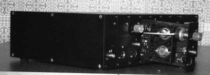
The amplifier was working well and had served me till 2001, the year when I returned to DIY hi-fi and realized to build something more advanced. The amp shown suffered from 2 major issues
the heatsinks were too small and continuous available power was thus reduced (similarly as in nowadays miniature TPA3255 amplifiers)
due to absence of Re resistors and poor idle current stabilization the idle current had to be kept very low, in order to prevent thermal runaway and destruction of power transistors. As a result, there was the crossover distortion. The same issues applied to original Sinclair modules.
Sinclair Z-30 rev2014 – my 45th anniversary project
In 2014, I got an idea to wipe dust from the Z-30 project and to make some modifications and make it a reliable amplifier with continuous maximum power capability, thermal stability and optimal bias of the output stage, to get rid off the crossover distortion.
This was running pretty well, with power specified at 50W/4ohm, thermal stabilization of idle current and appropriate heatsink.
Z-30 2019, last mod 50 years after
And this is my last (as for now 🙂 modification from 2019, 50 years after the original Z-30 was issued.
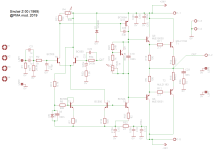
Schematics and PCB - this is the valid project schematics!
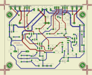
(Gerber files are attached at the bottom of this post in the z30_new.zip file, as well as the parts list in pdf)

Measurements
THD and THD+N vs. power at 1kHz/4ohm
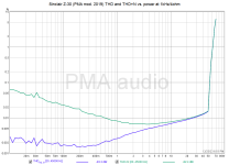
We can see that the amp gives 50W/4ohm
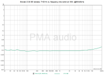
THD+N vs. frequency - pretty flat
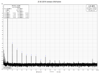
Distortion spectrum
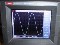
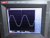
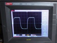
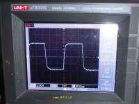
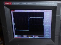
New: 20kHz square response
So this is my story of the Sinclair Z-30 amplifier. Even after 55 years, its basic topology is able to give good results. We have not moved much, since 🙂. Have fun with DIY!
Literature
[1] Project 60 Sinclair, Manual
[2] Dale, R.: The Sinclair Story
[3] Self, D.: Audio Power Amplifier Design Handbook, 4th edition, Newnes 2008
[4] Project 60 firmy Sinclair, Hudba a Zvuk, 7/1971
It was in 1969 when Sinclair Project 60 kit appeared on the market in UK and it contained Z-30 amplifier modules, advertised as 25W and 50W peak. It also advertised to be “the world's lowest distortion high fidelity amplifier”

and the news and kit description had soon, only few months later, appeared in our local hi-fi magazine Hudba a Zvuk.

Those days I was building my first amplifiers (with Singleton input stage and awkward circuit topology) and I was excited by Sinclair topology! The differential input stage, CCS VAS load, it was something completely new in the DIY world. However, for us behind the iron curtain, an unobtainium. We had the only chance, to learn and to design and build the thing ourselves.
Several years passed and after I finished my university studies I was still an enthusiastic DIYer and I have returned to the idea to build Z-30. So I took an original schematics

made some small mods like modification to +/- DC power supply (to get rid off the output coupling capacitor) and also changed the transistors, as the originals were not available here. This was probably a good idea, as my power transistors were more robust. And this was the result, in 1980

I have chosen a modular concept, with a motherboard and modules that could have been changed to make different amp configurations. There was an RIAA phono module, linear preamp module, bass/treble equalizer module, two modified Z-30 modules and a power supply. All except for Z-30 were my designs. It took years to realize the project and this was the result in 1987

The amplifier was working well and had served me till 2001, the year when I returned to DIY hi-fi and realized to build something more advanced. The amp shown suffered from 2 major issues
the heatsinks were too small and continuous available power was thus reduced (similarly as in nowadays miniature TPA3255 amplifiers)
due to absence of Re resistors and poor idle current stabilization the idle current had to be kept very low, in order to prevent thermal runaway and destruction of power transistors. As a result, there was the crossover distortion. The same issues applied to original Sinclair modules.
Sinclair Z-30 rev2014 – my 45th anniversary project
In 2014, I got an idea to wipe dust from the Z-30 project and to make some modifications and make it a reliable amplifier with continuous maximum power capability, thermal stability and optimal bias of the output stage, to get rid off the crossover distortion.
This was running pretty well, with power specified at 50W/4ohm, thermal stabilization of idle current and appropriate heatsink.
Z-30 2019, last mod 50 years after
And this is my last (as for now 🙂 modification from 2019, 50 years after the original Z-30 was issued.
Schematics and PCB - this is the valid project schematics!


(Gerber files are attached at the bottom of this post in the z30_new.zip file, as well as the parts list in pdf)
Measurements
THD and THD+N vs. power at 1kHz/4ohm

We can see that the amp gives 50W/4ohm
THD+N vs. frequency - pretty flat

Distortion spectrum

New: 20kHz square response

So this is my story of the Sinclair Z-30 amplifier. Even after 55 years, its basic topology is able to give good results. We have not moved much, since 🙂. Have fun with DIY!
Literature
[1] Project 60 Sinclair, Manual
[2] Dale, R.: The Sinclair Story
[3] Self, D.: Audio Power Amplifier Design Handbook, 4th edition, Newnes 2008
[4] Project 60 firmy Sinclair, Hudba a Zvuk, 7/1971
Attachments
Last edited:
Could it be the original quasi complementary output stage -without any countervailing measures such as Baxandall diodes or Quad 303 style triples- produced horrendous crossover distortion?
Could it be the original quasi complementary output stage -without any countervailing measures such as Baxandall diodes or Quad 303 style triples- produced horrendous crossover distortion?
Yes it did because due to absence of emitter resistors and due to small heatsinks the idle current had to be very very low, in fact class B, otherwise the amp went to thermal runaway.
---------
I forgot to post amplitude and phase response, so here it goes:
(one can read the gain from the plot as well)
This is measured as 2-channel measurement in STEPS. 2-channel method is a must, otherwise both amplitude and frequency responses are heavily influenced by DAC/ADC filter responses.
Sinclair gear was never cheap. The 1969 advert price for the Z30 corresponds to UKP120 today. And you needed two, plus a power supply, Plus the (three transistor per channel) preamp.
Those Sinclair booklets breathed magic around 1973: for nostalgic reasons I kept those many many years. A guy in my neighbourhood, who owned the Z30, complained about blowing up the output stage more than once. Back in the day Elektor (Elektuur in NL) already paid lots of attention to crossover distortion, so I never trusted the Sinclair power amps output stage.
I did, however, home brew a version of the Sinclair preamp.
I did, however, home brew a version of the Sinclair preamp.
That was basically one of those more or less disastrous designs of the early 70s, there was another one at Elektor IIRC, a 20W amplifier without emitter resistances for the OS, some good ideas like an enhanced VAS and a triple transistor for the negative rail but result was still awfull.
The preamp is nice, though, with a real baxandall, these were inexistant in about all japanese amplifiers even from the late 70s because there was royalties for this patented circuit.
The preamp is nice, though, with a real baxandall, these were inexistant in about all japanese amplifiers even from the late 70s because there was royalties for this patented circuit.
More precise measurement of step response rise time. Tr < 5us, F(-3dB) > 70kHz. Conservative, however prevents the amp from slewing. It can be adjusted by R2, C2 (post #1). I forgot to mention the idle current. I set 20mV across R14 (R15), so output stage idle current is <=100mA. The Vbe multiplier around Q9 keeps the idle current very well. C22 = 10pF.
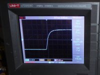
Finally, the measured sample. I have had 4 modules that have been operated since 2019 without any failure.


Finally, the measured sample. I have had 4 modules that have been operated since 2019 without any failure.
Last edited:
More precise measurement of step response rise time. Tr < 5us, F(-3dB) > 70kHz. Conservative, however prevents the amp from slewing.
I had to repeat the time domain measurements and re-measure with a fast function generator with rising edges of 10ns. The previous measurements that I made with an audio generator turned out to be unreliable, with badly defined square wave edges. I apologize for that.
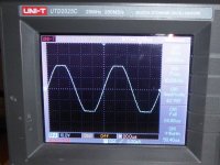
So, finally the correct results - rise time, 20kHz square response and 10kHz triangle response:
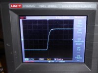
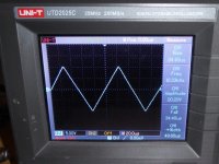
20kHz square
2-channel I/O measurements of rise time and fall time made with PicoScope USB oscilloscope


To me, clean, aperiodic time domain responses are as important or maybe more important than frequency domain spectrum measurements.
To me, clean, aperiodic time domain responses are as important or maybe more important than frequency domain spectrum measurements.
I rebuilt my Sinclair a few times. I added an EF buffer between the tone controls and a tape monitor switch after the phono preamp. You could run the phono preamp without RIAA but it was better to switch it out. Ironically, both vinyl and magnetic tape are now obsolete.
Eventually, I scrapped the Sinclair power amp for a hand made on vero board. Not sure anymore but I think it featured basically a "Blameless" topology with 3EF quasi outputs, ie the "protection" was a set of surplus 2n3772's that could drive a short.
Someday I will dig it out and see if it still works. I have a couple other old receivers because people gave me dead receivers for free. One that actually gets used is a Sansui G-4700 that I also "boosted" with a set of 2N3773's and more heat sink. It has nasty tone controls in the power amp feedback circuit, but I didn't bother changing that.
The Sinclair power amp actually worked fairly well and sounded great. I built a 2N3055 version once and used it at work. My biggest complaint is that he LTP bias is supply voltage sensitive. I built a little guitar amp for a friend using the Sinclair power amp design and he loved it.
- Home
- Amplifiers
- Solid State
- Sinclair (Project 60) 1969 Z-30 amplifier and my DIY mods, schematics + Gerbers
