Reference to this IMD scheme appeared recently in a thread posted by Never Get Old (NGO).
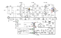
The amp I used for the test is the John L Stewart Bootstrapped Driver Scheme for driving Low Mu PP Triode amplifiers,
some work I did & published about 25 years ago.
The project at that time was strictly a 'Proof of Concept', something that could have easily done by others but was not.
People continued to build brute force drivers for their low mu triodes, even now.
The amp is a pair of 6080s in PP, all four of the triodes have their own 1.25K cathode resister. The bypass caps are each 100 microF.
The front end is a two stage Diff Amp of 6SL7 & 6SN7, simple resister tails to -150V. The amp has no balance controls & not epitomized at all.
After setting up the amplifier a 177R resister was used (1.25K*0,14) as Allen Wright had indicated.
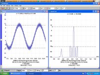
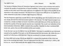
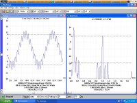
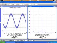
Tests were run in the SMPTE (Society of Motion Picture & Television Engineers) mode, a page outlining this is attached.
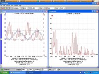
Other tests were run at One KHz mixed with 80 Hz. In each case it looks like there is something like a 10 db reduction in the IMD sidebands.
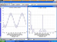
The last test shows both time & frequency domain images of the potential across the 177R resister.
Those with ears that respond to everything from DC to Green Light will probably hear a difference.
Some may not like the result, part of the IMD is gone!😀
Attachments
Its not really something new or different. All he did is change the cathode resistor size and the relative insertion loss is less in the cathode circuit. That is why you see no cathode resistor or 200 ohms or less on most push pull amps. So its not that out of the ordinary.After setting up the amplifier a 177R resister was used (1.25K*0,14) as Allen Wright had indicated.
Now compare construction type between your sundry 1.25K and a Anton-perry wirewound at 1.25K, that is designed specifically for low to no insertion loss, (Mills MRA5) you will see and hear a performance difference.
There is a well known historical paper by Kiebert published on the effect. (at least for 3rd harmonic)
http://www.clarisonus.com/Archives/...System Design Factors for Audio Ampifiers.pdf
If you look at the Philips datasheet for E55L, pg 9, for gm (S) versus current, you can see that two, back to back, in differential mode over a CCS will have a gm hump in the middle at balance. So total gm drops off as the pair become unbalanced. By adding a resistor in the tail (roughly 1/gm) the current can be increased toward the edges so as to keep gm more constant. Constant gm leads to less 3H distortion/ less IM. Different results for triodes versus pentodes however due to local N Fdbk.
https://www.diyaudio.com/community/threads/ltp-and-h3-distortion.283787/#post-4546788
--------------
We spent $10,000,000,000 on the new Webb telescope to confirm the Big Bang Theory. Instead, it instantly demolished it!!
Last edited:
I did a search of your activity on DIY, looks like just another Troll with time on his hands.Its not really something new or different. All he did is change the cathode resistor size and the relative insertion loss is less in the cathode circuit. That is why you see no cathode resistor or 200 ohms or less on most push pull amps. So its not that out of the ordinary.
Now compare construction type between your sundry 1.25K and a Anton-perry wirewound at 1.25K, that is designed specifically for low to no insertion loss, (Mills MRA5) you will see and hear a performance difference.
Not worth a proper response, so I will pass on this one.
If you're going to talk the talk, better be ready to walk the walk.
In case the Clarisonus archive doesn't load, John Attwood has the Keibert article here: https://www.one-electron.com/Archiv...System Design Factors for Audio Ampifiers.pdf
Was that what he was talking about? because he didn't provide a circuit example, nor said anything about a ccs because the OP was vague and most likely on purpose.If you look at the Philips datasheet for E55L, pg 9, for gm (S) versus current, you can see that two, back to back, in differential mode over a CCS will have a gm hump in the middle at balance. So total gm drops off as the pair become unbalanced. By adding a resistor in the tail (roughly 1/gm) the current can be increased toward the edges so as to keep gm more constant. Constant gm leads to less 3H distortion/ less IM. Different results for triodes versus pentodes however due to local N Fdbk.
This is what he wrote in case he decides to play a game with old and the wise:
The amp I used for the test is the John L Stewart Bootstrapped Driver Scheme for driving Low Mu PP Triode amplifiers,
some work I did & published about 25 years ago.
The project at that time was strictly a 'Proof of Concept', something that could have easily done by others but was not.
People continued to build brute force drivers for their low mu triodes, even now.
The amp is a pair of 6080s in PP, all four of the triodes have their own 1.25K cathode resister. The bypass caps are each 100 microF.
The front end is a two stage Diff Amp of 6SL7 & 6SN7, simple resister tails to -150V. The amp has no balance controls & not epitomized at all.
Oddly the E55L is very similar to the 7788/E810F except for heater current, both by Philips. Two of these are used in theIf you look at the Philips datasheet for E55L
output section of the HP 20 MHz plug in for the HP 140 Scope Series. We sold many of those circa 1960, a very popular scope.👍
Attachments
There is a well known historical paper by Kiebert published on the effect. (at least for 3rd harmonic)
http://www.clarisonus.com/Archives/...System Design Factors for Audio Ampifiers.pdf
If you look at the Philips datasheet for E55L, pg 9, for gm (S) versus current, you can see that two, back to back, in differential mode over a CCS will have a gm hump in the middle at balance. So total gm drops off as the pair become unbalanced. By adding a resistor in the tail (roughly 1/gm) the current can be increased toward the edges so as to keep gm more constant. Constant gm leads to less 3H distortion/ less IM. Different results for triodes versus pentodes however due to local N Fdbk.
https://www.diyaudio.com/community/threads/ltp-and-h3-distortion.283787/#post-4546788
--------------
We spent $10,000,000,000 on the new Webb telescope to confirm the Big Bang Theory. Instead, it instantly demolished it!!
Fascinating! I actually reinvented that in the 1990's, a weak inversion MOS version for use in pacemakers, https://repository.tudelft.nl/islandora/object/uuid:59af4dad-c9ea-4030-8596-73c0d5614968 I never knew it was a well-known technique in 1954...
Does anybody either than me see the irony of just how a few years ago jhstewart9 joined the forum with a big splash ready to wow the forum with how much he knew? You can't write irony this good! 😀
Talk is cheap. Show us some of your work so that we may marvel at it!😀So negatively opinionated. Either driven by a psychological disorder, jealousy, or intimidation. Regardless of the case, you earned the ignore button now.
Since you are in Calgary did you ever visit Bill Perkins of PEARL?Does anybody either than me see the irony of just how a few years ago jhstewart9 joined the forum with a big splash ready to wow the forum with how much he knew? You can't write irony this good! 😀
I hooked up with him about 40 yrs ago. Very busy guy with several projects in the system.
I don't recall much of a splash when I joined DIY but rather being challenged on a couple of points.
One had to do with the way I measured G2 resistance of voltage amplifier pentodes.
Don't recall who objected but that all went away pretty quick.
The other was by DY96?? a retired physics teacher on skin effect & proximity effect in transformers.
I got the sense that no one had ever heard of proximity effect. But its in there.
The transformers I worked on were mostly 3-phase, the kind that leave the building on a railway flat car.
At least I post the measurement results of all the tests I do. Few others on DIY do that. Mostly its just 'it sounds OK'.
For those not interested in my work PLS ignore my posts. THX
I did meet Bill Perkins once, Planet10 introduced me to him when the latter was visiting Calgary many years ago.
Actually, I was not trying to discount you in any way. Just trying to say, it's not wise to join this forum believing you already know everything and are just here to teach. IMHO, there's typically 2 kinds of successful members here, those with lots to learn, and those with less to learn.
Actually, I was not trying to discount you in any way. Just trying to say, it's not wise to join this forum believing you already know everything and are just here to teach. IMHO, there's typically 2 kinds of successful members here, those with lots to learn, and those with less to learn.
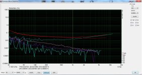
A case study on Keibert's paper. I used this in a KT88 PP classA amp. I had to go through a trial and error procedure since the amp runs with fixed bias and when I inserted a resistor at the cathodes it had to be readjusted and then the resistor had to be increased. Eventually, equilibrium was set at 82 ohm which for KT88 is indeed 1/gm. Attached measurement at 1W. I haven't kept a "before" measurement but H3 reduction was about 10dB. There was also a small reduction of H2. Note that the amp has zero GNFB.
Attachments
Nice lead, thanks - perhaps yet another case of taking an empirical approach by adding a roughly 1/gm resistor in the tail, then adjusting on test/to taste. 🙂By adding a resistor in the tail (roughly 1/gm) the current can be increased toward the edges so as to keep gm more constant. Constant gm leads to less 3H distortion/ less IM.
Probably beats the analytic approach of determining the first three polynomial coefficients a,b,c for i = ae + be2 + ce3 … that characterise your triode at your chosen operating point and then solving for the resistor value "k" ( to use Keibert's nomenclature).
Still leaves me wondering if the relationship Rk x 0.14 ≈ 1/gm at the chosen operating point has any analytic basis in triode operation?
Somewhere I recall mention that the optimum tail resistor value changes some with output power level. Of course the tube(s) gm would be changing with current too. so not too surprising. A thermionic diode or triode rp with the right rp value might track the optimum tail R there. But what a pain to find the right device to use. And more heat and cost too.
I don't think these research reports got implemented into commercial audio designs too often, unless there was some -Significant- cost saving potential. Could just crank up the tube gain for more N Fdbk instead.
But, now a-days we DO have DIY audio enthusiasts who want to try No-Fdbk or other exotic schemes, so these research tricks can be important.
For example, one -could- use a differential stage to control the output tube screen grid voltages, giving "ACTIVE ultra-linear", to get an "ultra-linear" design that is -ACTUALLY- linear and low Zout, but that never happened. All we got was mis-leading advertising and no screen supply. $$$
The "Active" differential stage would monitor attenuated plate output V's versus input signal to dynamically adjust the screen voltages for constant gain. It would be an interesting experiment to see what the screen grids -actually want- to get REAL "ultra-linear" results.
Last edited:
That sounds familiar. At least the MOS version I came up with without ever having heard of Kiebert (it's Kiebert and not Keibert according to the paper) could be designed for an optimally flat input-to-output relation, which would work best at low signal levels, or for an equiripple relation, which would improve signal handling at the expense of more distortion at low levels.
I can confirm that, and it is one of the reasons I do not use it.Somewhere I recall mention that the optimum tail resistor value changes some with output power level.
Nobody "knows everything" and everybody can still learn something, though some are not too willing to learn.I did meet Bill Perkins once, Planet10 introduced me to him when the latter was visiting Calgary many years ago.
Actually, I was not trying to discount you in any way. Just trying to say, it's not wise to join this forum believing you already know everything and are just here to teach. IMHO, there's typically 2 kinds of successful members here, those with lots to learn, and those with less to learn.
There are two kinds of members here, those who are afraid to blow stuff in the quest of knowledge, and those of us who think it's fun.
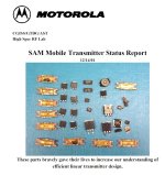
Motorola paid me well to blow stuff up. Here is the front page of a report from 2001 that I wrote detailing some new transmitter technology. I cut the bottom half off since it displayed the names of a dozen people who contributed to the project. Many of those parts that I blew up were one (or few) of a kind prototypes. Most of the RF transistors were housed in custom packages that myself and others had patented (the brass flanged parts). The silicon and SiC die came from Ultra RF, which was eaten by Cree, which became Wolfspeed, which..???...who appears to still make those high powered LDMOS parts.
As with any large group in a larger corporation, we had weekly meetings, monthly meetings, and quarterly meetings attended by the big bosses from Schaumburg. One of those quarterly meetings occurred on April 1, so I decided to drop a joke slide into the presentation. Unfortunately, I can't find it now over 20 years later, but it was discussing the management of some high slew rate power supply signals, that might require some unusual technology to manage. The picture showed a medium sized vacuum tube (a 6LU8 I think) stuck in the middle of my breadboard which itself was a 7 inch by 12 inch PC board with several different test circuits on it connected in a furball of wires and semi-rigid coaxial cables. It went over far better than my anonymous slide from a previous meeting that had an Excel graph of the department productivity as an inverse relationship to the time wasted making slides for meetings. fortunately, that one was not traceable back to me. The tube was, since it had been sitting on my desk for a couple years.
I applied the technology learned on the high efficiency linear transmitter project to......you guessed it, a high efficiency vacuum tube amplifier. It was submitted to a Microchip / Circuit Cellar magazine design contest where it won a prize and resulted in a published article.
Make learning fun, and keep at it, because when you stop learning you start growing old, and when you start growing old you begin to die.
Attachments
- Home
- Amplifiers
- Tubes / Valves
- Does Allen Wright's Cathode Bias Resister Scheme for IMD Reduction Work? Yes? No? Maybe!!
