darTZeel NHB-108/NHB-468: Curiously resp. strange Distortion Waveform in the Diagrams from Stereophile
- Solid State
- 8 Replies
Under
https://www.diyaudio.com/community/threads/dartzeel-amp-schematic-build-this.134362/
are describe various darTZeel clone versions but the diagram of the original models NHB-108 in fig 7 for distortion and noise waveform with fundamental notched out in the review under
https://www.stereophile.com/content/dartzeel-nhb-108-model-two-power-amplifier-measurements
so as the model NHB-468 in Fig. 9 under
https://www.stereophile.com/content/dartzeel-nhb-468-monoblock-power-amplifier-measurements
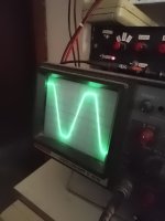
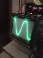
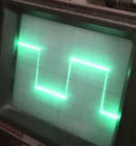
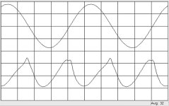
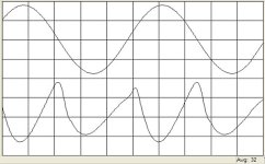
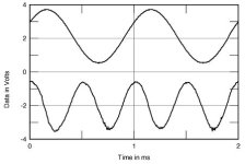
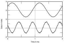
show an odd character of the distortion wave form;
only the lower half-wave has a sinusoidal character, while the upper half-wave is more like a triangular character (both mentioned diagrams also to see in the attached files No 1+2).
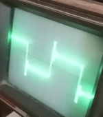
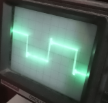
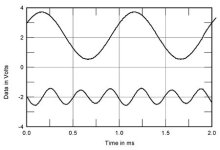
Every second half wave has the tip flattened (NHB-108) or rounded (NHB-468) in the upper area. Same diagram of attachment No 3-5 for the power amps Halcro DM38, Graaf GM200 and Pass Labs Aleph 4 don't show such an effect - lower and upper half-wave show identical character (clean H2 resp. H3 on Halcro's DM38).
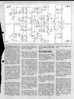
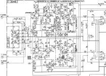
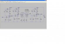
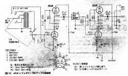
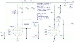
I haven't heard the models NHB-108 and NHB-468 from darTZeel, but - as long as it is not a measurement error on the equipment from Stereophile - there is anywhere a deficiency in the circuit design which is also audible - so I think (go to the simplified schematic from attached file No 6 resp. to https://6moons.com/audioreviews/dartzeel/108.html) so as to to the various other schematics from attachment, which have a certain similarity in terms of the input stages and due the fact, that only local (serial) feedback (and no global NFB) exists regarded the "End Millenium" from LC-Audio (go for the circuit description to
https://www.octave-electronics.com/lcaudio/temil.shtml)
Where is to find a circuit description in detail for this topology from darTZeel ?
Thank you very much for an information.
https://www.diyaudio.com/community/threads/dartzeel-amp-schematic-build-this.134362/
are describe various darTZeel clone versions but the diagram of the original models NHB-108 in fig 7 for distortion and noise waveform with fundamental notched out in the review under
https://www.stereophile.com/content/dartzeel-nhb-108-model-two-power-amplifier-measurements
so as the model NHB-468 in Fig. 9 under
https://www.stereophile.com/content/dartzeel-nhb-468-monoblock-power-amplifier-measurements
show an odd character of the distortion wave form;
only the lower half-wave has a sinusoidal character, while the upper half-wave is more like a triangular character (both mentioned diagrams also to see in the attached files No 1+2).
Every second half wave has the tip flattened (NHB-108) or rounded (NHB-468) in the upper area. Same diagram of attachment No 3-5 for the power amps Halcro DM38, Graaf GM200 and Pass Labs Aleph 4 don't show such an effect - lower and upper half-wave show identical character (clean H2 resp. H3 on Halcro's DM38).
I haven't heard the models NHB-108 and NHB-468 from darTZeel, but - as long as it is not a measurement error on the equipment from Stereophile - there is anywhere a deficiency in the circuit design which is also audible - so I think (go to the simplified schematic from attached file No 6 resp. to https://6moons.com/audioreviews/dartzeel/108.html) so as to to the various other schematics from attachment, which have a certain similarity in terms of the input stages and due the fact, that only local (serial) feedback (and no global NFB) exists regarded the "End Millenium" from LC-Audio (go for the circuit description to
https://www.octave-electronics.com/lcaudio/temil.shtml)
Where is to find a circuit description in detail for this topology from darTZeel ?
Thank you very much for an information.
Attachments
-
 darTZeel NHB-108 THD waveform.jpg32.7 KB · Views: 255
 -
 darTZeel NHB-468 THD waveform.jpg33.7 KB · Views: 191
 -
 Halcro DM38 THD waveform.jpg16.4 KB · Views: 171
 -
 Graaf GM 200 THD waveform.jpg16.2 KB · Views: 176
 -
 Pass Aleph 4 THD waveform .jpg13.8 KB · Views: 282
 -
 dartzeel NHB-108 simplified schematic.gif32.8 KB · Views: 423
 -
 AVM Stereoplay diy-amp.jpg225.9 KB · Views: 430
 -
C_...A-AVM-Stereoplay.ckt.pdf12.1 KB · Views: 92
-
 OMTEC CA25.jpg401.8 KB · Views: 505
 -
 End Millenium (LC-Audio) simplified schem.gif11.9 KB · Views: 367
 -
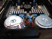
 dartzeel_nhb468_002-scaled.jpg187.8 KB · Views: 265
 -
 dartzeel_nhb468_001.jpg85.3 KB · Views: 215
 -
 NHB-108-front.jpg201.2 KB · Views: 207
 -
 NHB-108 rear.jpg299.9 KB · Views: 216
 -
 NHB-108-I.jpg870.4 KB · Views: 233
 -
 NHB-108-II.jpg570.8 KB · Views: 275


![DSCN0123[1].JPG](/community/data/attachments/1227/1227740-44059cbf8dd2e8db032004bbb9606adc.jpg?hash=RAWcv43S6N)