I've been investigating different ways of building a better turntable plinth. There appears to be a lot of myth and misconception surrounding the techniques used in proper plinth design, and not just from the DIY crowd. I did a lot of on-line research, but the best resource I found was this site:
http://qualia.webs.com/plinthbuilding.htm
He also posts at these sites as well as others:
plinth building - audio qualia
Lenco Reference :: Damping factors
audio qualia - Information
The author does a great job of explaining the physics behind a seemingly simple concept of building a supporting structure for your turntable's components and applies the necessary amount of scientific rigor to the problem, rather than guessing at the results or just hap-hazzardly combining materials that may look good, but produce specious results. I highly recommend anyone interested in the subject to read through his website, but the short version of it (if I may paraphrase and with apologies to Bryan) goes something like this:
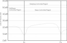
There are 3 areas of acoustic interest regarding the plinth, divided by 2 boundaries: One measured (resonant frequency) and one computed (critical frequency). All solid objects will have a resonant frequency (or multiple Fr) at which they will vibrate when excited properly. The critical frequency is computed and is affected by the density (P), thickness(h), Young's modulus (E) and Poisson's ratio (v) of the material: fc=[c^2*sqrt(12*P*(1-v^2)/E)]/(2*PI*h) (where c=speed of sound in air). The critical frequency is the frequency where the material becomes acoustically transparent. Vibrations that originate in the plinth (or a component such as a motor attached to the plinth) will propagate freely into other components and radiate sound into the air. Airborne vibrations at Fc or above, will freely enter the plinth and propagate into other components attached to the plinth.
Below the resonant frequency, vibrations are mainly controlled by the bending stiffness of the material. Between the Fr and Fc, mass loading mainly controls the vibrations and above Fc, only damping controls the vibrations, although damping has an effect across all 3 areas. Ideally, you want some spacing between Fr and Fc for mass loading to be effective; if Fc is at or below Fr, increasing mass will have no effect on vibration control. Increasing thickness lowers Fc and raises Fr, which are both undesirable, so you want a material which is thick enough to provide good stiffness, but not to thick that causes Fr and Fc to converge or cross. The ideal single material would be very dense, stiff (but not too stiff), thin and have good natural damping characteristics. Unfortunately, there doesn't seem to be a single material that hits every check box, so the next best thing is to combine materials into a layered construction.
The situation described above is valid for a plinth made of a single layer of homogenous material. It gets a little more complicated when you start to layer different materials. Finite Element Analysis may be the proper tool to analyze layered approaches, but simulators are only as good as the models you feed them and so far, I haven't found an adequate model for multilayer panels. I took a more empirical approach and measured/computed individual materials that seemed like good candidates, combined them in a number of ways and measured the composite results.
One of the most common approaches is to use a technique called Constrained Layer Damping or CLD. A number of mfrs claim to use CLD plinths, but technically, they aren't CLD. CLD uses two stiff outer layers that are attached to an inner damping layer via a visco-elastic layer between each section that dissipates the vibrations as heat when the layers flex. The VE layer needs to be elastic, but have high sheer strength and be thin enough not to create a "sprung" design. The author of the reference website explained it this way: If you hold a piece of glass between your fingers and strike it, it will ring. If you loosely place another piece of glass on top of it, the first layer will be damped and ring for a much shorter time. If you tightly bond both pieces of glass together, they act as a single layer of glass and will ring when struck again. I'm confused by some of the commercial designs that seem to ignore the basic premise of CLD design. Instead of a damping layer sandwiched between 2 stiff layers, with visco-elastic material between them, they have a stiff layer (aluminum) sandwiched between 2 damping layers (MDF or acrylic) with rigid glue holding them together, and fairly substantial hardware bolted through all three layers (feet, platter bearing, tone arm mount) that will reduce the isolation created by separate layers. ClearAudio does a good job of this using thin aluminum outer layers, with a thick layer of Panzerholz between them, which has excellent damping characteristics. VPI uses MDF-Aluminum-MDF which does not provide the optimum characteristics, and bolts the layers together as well as gluing them. When I eventually settled on the materials and construction that I wanted to use, I mounted the platter bearing and tone arm to the top stiff layer only, they are isolated from the damping layer and the bottom stiff layer. Likewise, the feet are attached to the bottom stiff layer only and isolated from the damping layer and top stiff layer. This provides maximum coupling between the platter and tonearm, but minimum coupling between the platter/tonearm and the outside world.
http://qualia.webs.com/plinthbuilding.htm
He also posts at these sites as well as others:
plinth building - audio qualia
Lenco Reference :: Damping factors
audio qualia - Information
The author does a great job of explaining the physics behind a seemingly simple concept of building a supporting structure for your turntable's components and applies the necessary amount of scientific rigor to the problem, rather than guessing at the results or just hap-hazzardly combining materials that may look good, but produce specious results. I highly recommend anyone interested in the subject to read through his website, but the short version of it (if I may paraphrase and with apologies to Bryan) goes something like this:
There are 3 areas of acoustic interest regarding the plinth, divided by 2 boundaries: One measured (resonant frequency) and one computed (critical frequency). All solid objects will have a resonant frequency (or multiple Fr) at which they will vibrate when excited properly. The critical frequency is computed and is affected by the density (P), thickness(h), Young's modulus (E) and Poisson's ratio (v) of the material: fc=[c^2*sqrt(12*P*(1-v^2)/E)]/(2*PI*h) (where c=speed of sound in air). The critical frequency is the frequency where the material becomes acoustically transparent. Vibrations that originate in the plinth (or a component such as a motor attached to the plinth) will propagate freely into other components and radiate sound into the air. Airborne vibrations at Fc or above, will freely enter the plinth and propagate into other components attached to the plinth.
Below the resonant frequency, vibrations are mainly controlled by the bending stiffness of the material. Between the Fr and Fc, mass loading mainly controls the vibrations and above Fc, only damping controls the vibrations, although damping has an effect across all 3 areas. Ideally, you want some spacing between Fr and Fc for mass loading to be effective; if Fc is at or below Fr, increasing mass will have no effect on vibration control. Increasing thickness lowers Fc and raises Fr, which are both undesirable, so you want a material which is thick enough to provide good stiffness, but not to thick that causes Fr and Fc to converge or cross. The ideal single material would be very dense, stiff (but not too stiff), thin and have good natural damping characteristics. Unfortunately, there doesn't seem to be a single material that hits every check box, so the next best thing is to combine materials into a layered construction.
The situation described above is valid for a plinth made of a single layer of homogenous material. It gets a little more complicated when you start to layer different materials. Finite Element Analysis may be the proper tool to analyze layered approaches, but simulators are only as good as the models you feed them and so far, I haven't found an adequate model for multilayer panels. I took a more empirical approach and measured/computed individual materials that seemed like good candidates, combined them in a number of ways and measured the composite results.
One of the most common approaches is to use a technique called Constrained Layer Damping or CLD. A number of mfrs claim to use CLD plinths, but technically, they aren't CLD. CLD uses two stiff outer layers that are attached to an inner damping layer via a visco-elastic layer between each section that dissipates the vibrations as heat when the layers flex. The VE layer needs to be elastic, but have high sheer strength and be thin enough not to create a "sprung" design. The author of the reference website explained it this way: If you hold a piece of glass between your fingers and strike it, it will ring. If you loosely place another piece of glass on top of it, the first layer will be damped and ring for a much shorter time. If you tightly bond both pieces of glass together, they act as a single layer of glass and will ring when struck again. I'm confused by some of the commercial designs that seem to ignore the basic premise of CLD design. Instead of a damping layer sandwiched between 2 stiff layers, with visco-elastic material between them, they have a stiff layer (aluminum) sandwiched between 2 damping layers (MDF or acrylic) with rigid glue holding them together, and fairly substantial hardware bolted through all three layers (feet, platter bearing, tone arm mount) that will reduce the isolation created by separate layers. ClearAudio does a good job of this using thin aluminum outer layers, with a thick layer of Panzerholz between them, which has excellent damping characteristics. VPI uses MDF-Aluminum-MDF which does not provide the optimum characteristics, and bolts the layers together as well as gluing them. When I eventually settled on the materials and construction that I wanted to use, I mounted the platter bearing and tone arm to the top stiff layer only, they are isolated from the damping layer and the bottom stiff layer. Likewise, the feet are attached to the bottom stiff layer only and isolated from the damping layer and top stiff layer. This provides maximum coupling between the platter and tonearm, but minimum coupling between the platter/tonearm and the outside world.
Attachments
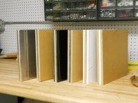
Materials
The materials I investigated were MDF, aluminum, granite and Corian. Aluminum and granite are approximately the same density, but granite has higher bending stiffness. MDF is neither dense nor stiff, but is said to have good damping characteristics. Corian is less dense than aluminum or granite, has a lower Young's modulus than the two, but is still quite stiff (but not too stiff) and measured nearly the same as MDF for natural damping.
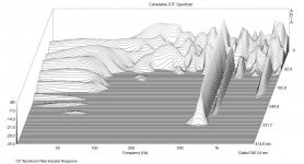
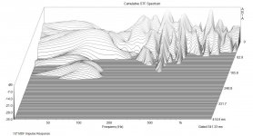
I created a jig to measure the resonant frequency (Fr) of the materials. All of the materials were approximately 1/2" thick and cut into 1 foot square panels. If the material is held tightly or coupled to another object (platform, vise etc.), the natural Fr of the material will be damped, so the jig has 2 points below the panel for support and one adjustable point (to keep the panel level) above the panel. A 3 axis accelerometer is firmly attached to the edge of the panel, the panel is placed in the jig and excited into resonance by dropping a golf ball onto the center of the panel from a height of 30 inches. The output of the accelerometer is connected to my laptop running Arta software which can record and graph the time domain, frequency spectrum and cumulative decay response of each material.
As expected, the aluminum and granite showed the lowest deflection at low frequencies due to their inherent stiffness. They also rang like a bell at the resonant frequency (621 Hz for aluminum, 708Hz for granite) and for sustained periods. The aluminum plate also produced an audible ring at high frequency (I'm guessing higher than 5kHz which is outside the range of the accelerometer) for almost 4-5 seconds after impact. Both 1/2" aluminum and granite panels have similar computed critical frequencies of ~1kHz, so not a lot of separation between Fr and Fc, where mass will have a positive affect.
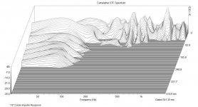
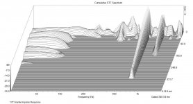
The MDF and Corian had similar Fr which were much lower than the other two materials. MDF Fr was 398 Hz and Corian was 416Hz. Both resonances produced lower amplitude responses and were much shorter lived than aluminum or granite. Corian has a computed Fc of 2150Hz. I didn't compute the Fc for MDF, as I couldn't find all of the parameters needed for the material and it will be used as a damping layer rather than the stiff outer layer.
The materials I investigated were MDF, aluminum, granite and Corian. Aluminum and granite are approximately the same density, but granite has higher bending stiffness. MDF is neither dense nor stiff, but is said to have good damping characteristics. Corian is less dense than aluminum or granite, has a lower Young's modulus than the two, but is still quite stiff (but not too stiff) and measured nearly the same as MDF for natural damping.
I created a jig to measure the resonant frequency (Fr) of the materials. All of the materials were approximately 1/2" thick and cut into 1 foot square panels. If the material is held tightly or coupled to another object (platform, vise etc.), the natural Fr of the material will be damped, so the jig has 2 points below the panel for support and one adjustable point (to keep the panel level) above the panel. A 3 axis accelerometer is firmly attached to the edge of the panel, the panel is placed in the jig and excited into resonance by dropping a golf ball onto the center of the panel from a height of 30 inches. The output of the accelerometer is connected to my laptop running Arta software which can record and graph the time domain, frequency spectrum and cumulative decay response of each material.
As expected, the aluminum and granite showed the lowest deflection at low frequencies due to their inherent stiffness. They also rang like a bell at the resonant frequency (621 Hz for aluminum, 708Hz for granite) and for sustained periods. The aluminum plate also produced an audible ring at high frequency (I'm guessing higher than 5kHz which is outside the range of the accelerometer) for almost 4-5 seconds after impact. Both 1/2" aluminum and granite panels have similar computed critical frequencies of ~1kHz, so not a lot of separation between Fr and Fc, where mass will have a positive affect.
The MDF and Corian had similar Fr which were much lower than the other two materials. MDF Fr was 398 Hz and Corian was 416Hz. Both resonances produced lower amplitude responses and were much shorter lived than aluminum or granite. Corian has a computed Fc of 2150Hz. I didn't compute the Fc for MDF, as I couldn't find all of the parameters needed for the material and it will be used as a damping layer rather than the stiff outer layer.
Attachments
Last edited:
Layers
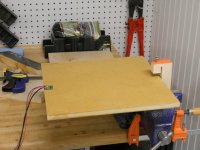
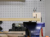
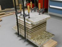
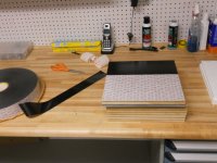
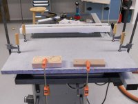
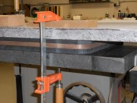
I cut three 1 foot squares from each material and created two constructed layers for each of the stiff materials (aluminum, granite and Corian), layered Stiff-MDF-Stiff and MDF-Stiff-MDF. The visco-elastic layer between the panels is 3M VHB double sided tape. The tape is thin (40 mils), very elastic, high sheer strength and very high bond (VHB) strength (they use these tapes to replace screws on trucks and boats), so it meets all of the requirements for the connecting layer. The tape bonds well to smooth hard surfaces like aluminum, granite and Corian, but not so well to MDF. I sealed the outer skin of the MDF with a 2 part epoxy sealer from Smith Systems (CPES), which bonds extremely well to wood and provides an epoxy like surface for the VHB tape to bond to. The VHB tape achieves better than 90% bonding strength after 24 hours, so I tightly clamped all of the composite layers together between 2 slabs of granite using multiple wood clamps for a day.
I measured the impulse response of the composite layers by supporting them on 4 posts, similar to how they would be used as a plinth. All 6 composite layups measured markedly better than any of the single materials, but the clear winner was Corian-MDF-Corian. The vibrations were lower in amplitude and much better damped than any of the other combinations. Not surprisingly, the aluminum and granite composites were the worse, with the granite-MDF-granite showing some surprising oscillations (low amplitude but poorly damped and with a wider bandwidth than any other combination). Also telling was that MDF-aluminum-MDF was worse than aluminum-MDF-aluminum, although this was predictable as MDF-aluminum-MDF is not a true CLD construction.
Attachments
-
 DSCN1424.JPG284.7 KB · Views: 912
 -
 DSCN1423.JPG286.3 KB · Views: 807
 -
 DSCN1419.JPG289.5 KB · Views: 901
 -
 DSCN1425.JPG250.8 KB · Views: 804
 -
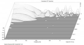 Table Top Impulse MDF-Granite-MDF CLD.jpg145.3 KB · Views: 615
 -
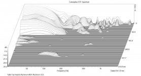 Table Top Impulse Aluminum-MDF-Aluminum CLD.jpg148.4 KB · Views: 859
 -
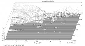 Table Top Impulse MDF-Aluminum-MDF CLD.jpg156.7 KB · Views: 617
 -
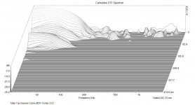 Table Top Impulse Corian-MDF-Corian CLD.jpg136.3 KB · Views: 611
 -
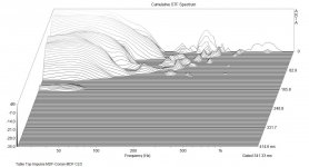 Table Top Impulse MDF-Corian-MDF CLD.jpg140.2 KB · Views: 600
 -
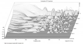 Table Top Impulse Granite-MDF-Granite CLD.jpg204.2 KB · Views: 598
Last edited:
The plinth
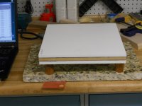
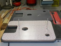
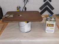
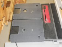
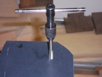
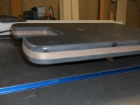
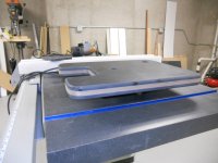
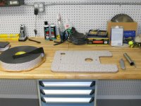
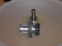
I cut the center MDF panel to size first as it is the easiest material to work with. I cut the Corian panels slightly oversized and will trim them flush with the MDF layer using a flush trim router bit after they are bonded to the MDF. All of the holes are cut in the panels and threads tapped for the tonearm mounting screws (Corian machines very well with standard woodworking tools). The platter bearing and tonearm holes in the top layer are properly sized for mounting each, and the holes in the other two layers are oversized to isolate the platter and tone arm hardware from the damping layer and the bottom stiff layer. The threads for the feet are in the bottom layer only and are isolated from the damping layer and top stiff layer. I drilled 2 alignment holes through the bottom and damping layer and only part way into the bottom of the top layer. I will use two 1/4" aluminum rods to align the layers as they are put together with the VHB tape.
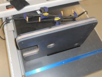
The MDF is sealed on all sides using Smith Systems CPES. It take several days for all the VOCs to outgas and for the epoxy to cure properly. I attached a thin walnut veneer to the outside edge of the MDF; the veneer has a hot glue layer attached and is melted in place using a clothes iron. The VHB is attached to both sides of the MDF layer, then the protective layer of the VHB tape is removed from the top side and mated to the top layer of Corian using the alignment rods. The bottom protective layer is removed from the VHB tape and the mating bottom layer of Corian is put into place. With the alignment rods removed, I clamped the composite structure between two layers of granite for 24 hours until the VHB tape achieves maximum bonding strength.
Next, the excess Corian is removed with a flush cut trim bit in a router so the edge of the Corian is flush with the walnut veneer layer of the MDF. The edges of the Corian are eased with an 1/8" round over bit in the router, both top and bottom layers. All of the routed edges are smoothed with 220 grit sandpaper and the plinth is ready for the final polishing. I opted to send the plinth to my local counter top fabricators for polishing and they did an excellent job of it.
I cut the center MDF panel to size first as it is the easiest material to work with. I cut the Corian panels slightly oversized and will trim them flush with the MDF layer using a flush trim router bit after they are bonded to the MDF. All of the holes are cut in the panels and threads tapped for the tonearm mounting screws (Corian machines very well with standard woodworking tools). The platter bearing and tonearm holes in the top layer are properly sized for mounting each, and the holes in the other two layers are oversized to isolate the platter and tone arm hardware from the damping layer and the bottom stiff layer. The threads for the feet are in the bottom layer only and are isolated from the damping layer and top stiff layer. I drilled 2 alignment holes through the bottom and damping layer and only part way into the bottom of the top layer. I will use two 1/4" aluminum rods to align the layers as they are put together with the VHB tape.
The MDF is sealed on all sides using Smith Systems CPES. It take several days for all the VOCs to outgas and for the epoxy to cure properly. I attached a thin walnut veneer to the outside edge of the MDF; the veneer has a hot glue layer attached and is melted in place using a clothes iron. The VHB is attached to both sides of the MDF layer, then the protective layer of the VHB tape is removed from the top side and mated to the top layer of Corian using the alignment rods. The bottom protective layer is removed from the VHB tape and the mating bottom layer of Corian is put into place. With the alignment rods removed, I clamped the composite structure between two layers of granite for 24 hours until the VHB tape achieves maximum bonding strength.
Next, the excess Corian is removed with a flush cut trim bit in a router so the edge of the Corian is flush with the walnut veneer layer of the MDF. The edges of the Corian are eased with an 1/8" round over bit in the router, both top and bottom layers. All of the routed edges are smoothed with 220 grit sandpaper and the plinth is ready for the final polishing. I opted to send the plinth to my local counter top fabricators for polishing and they did an excellent job of it.
Attachments
-
 DSCN1443.JPG276.7 KB · Views: 802
 -
 DSCN1442.JPG251.8 KB · Views: 979
 -
 DSCN1441.JPG299 KB · Views: 1,021
 -
 DSCN1430.JPG284.1 KB · Views: 1,001
 -
 DSCN1431.JPG278.6 KB · Views: 923
 -
 DSCN1439.JPG248 KB · Views: 884
 -
 DSCN1446.JPG286.4 KB · Views: 875
 -
 DSCN1447.JPG265.9 KB · Views: 1,072
 -
 DSCN1448.JPG268.6 KB · Views: 1,070
 -
 DSCN1440.JPG305.5 KB · Views: 896


Pyramid Rules!
Great post Bill.
As an idea how about building the plinth the size just to accommodate the platter and tonearm and leave out the pieces that encircle the motor. Would that not improve the plinths resonant character?
Jam
On a lighter note................
Great post Bill.
As an idea how about building the plinth the size just to accommodate the platter and tonearm and leave out the pieces that encircle the motor. Would that not improve the plinths resonant character?
Jam
On a lighter note................
Attachments

I notice that none of the materials tested could be labelled inherently well damped by the Audio Qualia data.
damping factor values - audio qualia
In fact some of them measure very poorly indeed. I acknowledge that in layers they may well perform markedly differently as the OP has observed. However it seems illogical to start with poorly damped materials and combine them in layers to seek a superior composite. Neither do any of the sandwich composites conform to what I understand to be CLD where a thin visco-elastic layer separates identical layers. If the objective is a plinth material exhibiting superior damping, then neither the materials or the construction seem to be optimal. On the Audio Qualia damping factor measurements, the standout materials are Panzerholz/Permali (very expensive, hard to source, difficult to work with) and polyester resin/bentonite composite (relatively cheap materials but requires mold). I look forward to the subjective testing of the corian/mdf/corian sandwich.
Well first off I must say that it looks wonderful, but as Bon said, not convinced its CLD in the academic sense. Having looked at the audio qualia site it does appear that they missed the question that needs answering, which is what needs damping in the first place. Damping is not isolation and I think a lot of the confusion out there is that people are not sure when you are damping and when you are isolating.
Doesn't stop it looking great though which will do more for SQ than anything else")
Doesn't stop it looking great though which will do more for SQ than anything else
I was getting ready to assemble a my VPI clone, Acrylic, Alum, Acrylic and saw this...just in time? Out goes the Alum and in goes the MFD. Question, I have the VPI large 4" puck/donut that attaches to the bearing body with a cap screw through the center. Are you using that or some kind of sleeve, due to the length of the bearing body?
I did intend on EAR IsoDamp between layers, not through bolted in any way and "donut" attached to the bearing body and top layer only. Maybe I'll try the 3M foam tape instead. It's got to be cheaper than the EAR material.
I did intend on EAR IsoDamp between layers, not through bolted in any way and "donut" attached to the bearing body and top layer only. Maybe I'll try the 3M foam tape instead. It's got to be cheaper than the EAR material.
This is excellent work and a marvelous finished result. Congratulations!
Couple questions:
After the walnut veneer was affixed, how was it sealed (oil, polyurethane, etc)?
How was the veneer protected during the corian polishing procedure?
I sealed the veneer with Tung Oil after it came back from the finishers. The veneer is 40mils thick and any additional sanding was very light. I believe they protected the veneer with tape for the final polish which is done with a liquid compound.
I was getting ready to assemble a my VPI clone, Acrylic, Alum, Acrylic and saw this...just in time? Out goes the Alum and in goes the MFD. Question, I have the VPI large 4" puck/donut that attaches to the bearing body with a cap screw through the center. Are you using that or some kind of sleeve, due to the length of the bearing body?
I did intend on EAR IsoDamp between layers, not through bolted in any way and "donut" attached to the bearing body and top layer only. Maybe I'll try the 3M foam tape instead. It's got to be cheaper than the EAR material.
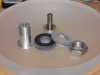
I made a 1/2" thick doughnut out of Corian for a spacer on the bearing mount. It is the same diameter as the washer.
The 3M tape was ~$110 for the roll (72 yds x 2.5").
If you have a way to test the results of you panel(s), I would do that before throwing away any attempts.
Attachments
Last edited:
@Bon- Panzerholz is very expensive and difficult to source (especially in the US), although it would most likely have worked better than MDF. Corian is similar to Polyester/bentonite in construction (acrylic polymer and alumina trihydrate crystals) and it certainly measured the best of the 4 materials; I didn't see data on the audioqualia site for it? It would have been interesting to build a laminate structure out of Corian and Panzerholz.
@Ben & Bon- I've seen CLD described as a single rigid layer bonded to a single damping layer, and I've also seen the term applied to rigid-damp-rigid structures; perhaps there is a more accurate name for the latter?
I think the principal is the same however: A structure that damps vibrations through flexing and dissipates the energy as heat in the damping layer.
Thanks to everyone for the positive comments.
Hello pyramid, good work there, just one of the very few who is able and willing to put in some investigative work, rather than leave it to subjective means, or worst still, build and hope.
However, I would point out a few things. Your test rig clamps one edge, and you are measuring with your accelerometer on the opposite edge. If you are dropping your golf ball near to the middle of the test piece, only transverse waves are going to reach your accelerometer (at higher frequencies), which, if it is like some of mine, have a limited bandwidth in the Z direction compared to the X or Y directions. This may be the reason for the higher than expected fundamental resonance frequencies. My calculations give results about an octave lower than yours, although F1,2/F2,1 and F2,2 are in agreement with your loverly waterfall graphs. You may like to use something harder than a golf ball, I use steel balls. The driving point impedance may affect results.
I would agree that the materials tested fall into two groups, (aluminium/granite) and (mdf/Corian), although none have any damping to speak of, on their own.
I must agree with Bon about choice of materials, although one manufacturer of after-market parts for a very well respected turntable design sent a piece of a composite made from two of the materials you tested, and it performed quite well. Also, as Bon has pointed out, your construction is not cld. I think you have fallen into the same maelstrom as the manufacturers you have maligned. Cld is applied to a (thin) vibrating panel, and consists of a thin viscoelastic material, constrained by another thin panel, usually made of the same material as the vibrating panel, but certainly no stiffer than it. Your construction is a glued laminate or glulam, as it is known in the trade. A vibrating panel with a damping layer applied is called extensional damping, and is not as good as cld.
As you point out, suitable materials for plinth duty seem to be very expensive/hard to source or require extensive work. Because of this, I have headed in another direction and I am currently looking at laminates (mainly plastics) and modified wood. The wood I am using is either oak or idigbo, and it is being modified by various liquid preparations, maybe like a poor man's panzerholz! although synthetic resins are not involved.
However, with your glulam construction, losses should be around the 30-35dB range, Fr about 375Hz and Fc about 1122Hz, so a bit of useful mass losses. I'm assuming a damping factor of 0.2, any less, and your loses will not be as good, maybe 5-6dB worse for DF of 0.1
HTH
Last edited:
- Home
- Source & Line
- Analogue Source
- DIY CLD Plinth Design--A measured Approach