I am going to begin a new thread and consolidate my rebuild process . I acquired a pair of Beveridge 2sw-2 ( maybe they are 1s) in January. I have been reluctant to begin work due to life circumstances , however, over the past couple of weeks things have changed and I felt like tackling them.
I own a Beveridge Model 3s that has been converted to a all tube input and Direct Drive tube output amp . We will see what is up in the comparison when the time comes.
This pair is physically in good condition however, the amps are slightly different. One is raw aluminum one is painted black. My understanding from another forum is that the aluminum amp is a later model. My guess is there may have been some kind of failure back in the day and the amp was either returned for a replacement or rebuilt. Each amp has the sub woofer amp and active crossover. The black amp has a switch that affects the input capacitance of the SS driver amp. I read that this was a eq that Modjeski called " air" and "more air" . The only other difference is that the aluminum amp has Modjeski's servo control on the fan and the black amp does not. Both SS driver boards and HV boards are identical in each amp.
Both amps have been muddled throughout the years although the boards themselves are in remarkably good shape.
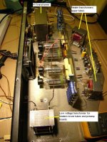
I began with a thorough cleaning. The aluminum amp had a catastrophic failure of the HV cap string and had underrated HV diodes in place , a couple were cracked. The original diodes were listed as M40- I could not find any data on them. In the end I used Diotec HV6 diodes 6Kv 200mA as replacements.
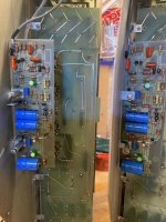
All HV caps and load sharing resistors were changed along with all diodes - I had to end up changing the caps in the voltage multiplier as they were just not doing their job.
These were sourced from Surplus Sales of Nebraska .1mfd and 4kV - the form factor was almost exact to original.
Lots is said about the HV transformer and my impression is that some might believe it supplies 3.2 kV directly. It does not. the ac output of both my transformers on the HV is 1.21kV and it feeds the multiplier.
I changed all the female banana jacks as they pitted and blackened with age , I did not want HV tracking on these. They are expoxied in so a bit of pain, I was looking for nylon nuts to secure the banana jacks but none to be found... I ended up threading 5/16" size to metric thread of the banana jacks.- I did not want any metal nuts and I wanted to be able to replace in the future if necessary.
I have one amp reliably running right now and will begin the second one. The panels measure equivalent from stator to stator and from each stator to diaphragm - there was some concern initially with corroded eyelet connectors but that was resolved. It runs pretty hot drawing about 2.2 amps @120V . Voltages are good at about 3100v +/-

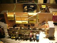
Some pics from this journey. One more to go and then some testing with the panels.


I own a Beveridge Model 3s that has been converted to a all tube input and Direct Drive tube output amp . We will see what is up in the comparison when the time comes.
This pair is physically in good condition however, the amps are slightly different. One is raw aluminum one is painted black. My understanding from another forum is that the aluminum amp is a later model. My guess is there may have been some kind of failure back in the day and the amp was either returned for a replacement or rebuilt. Each amp has the sub woofer amp and active crossover. The black amp has a switch that affects the input capacitance of the SS driver amp. I read that this was a eq that Modjeski called " air" and "more air" . The only other difference is that the aluminum amp has Modjeski's servo control on the fan and the black amp does not. Both SS driver boards and HV boards are identical in each amp.
Both amps have been muddled throughout the years although the boards themselves are in remarkably good shape.
I began with a thorough cleaning. The aluminum amp had a catastrophic failure of the HV cap string and had underrated HV diodes in place , a couple were cracked. The original diodes were listed as M40- I could not find any data on them. In the end I used Diotec HV6 diodes 6Kv 200mA as replacements.
All HV caps and load sharing resistors were changed along with all diodes - I had to end up changing the caps in the voltage multiplier as they were just not doing their job.
These were sourced from Surplus Sales of Nebraska .1mfd and 4kV - the form factor was almost exact to original.
Lots is said about the HV transformer and my impression is that some might believe it supplies 3.2 kV directly. It does not. the ac output of both my transformers on the HV is 1.21kV and it feeds the multiplier.
I changed all the female banana jacks as they pitted and blackened with age , I did not want HV tracking on these. They are expoxied in so a bit of pain, I was looking for nylon nuts to secure the banana jacks but none to be found... I ended up threading 5/16" size to metric thread of the banana jacks.- I did not want any metal nuts and I wanted to be able to replace in the future if necessary.
I have one amp reliably running right now and will begin the second one. The panels measure equivalent from stator to stator and from each stator to diaphragm - there was some concern initially with corroded eyelet connectors but that was resolved. It runs pretty hot drawing about 2.2 amps @120V . Voltages are good at about 3100v +/-
Some pics from this journey. One more to go and then some testing with the panels.
Last edited by a moderator:
kcin, congrats to a remarkable speaker!
A weak point is the power transformer. There is a way to save the transformer from internal arching, that is to rebuild the voltage multiplier so that the secondary winding is grounded, instead of floating at 1550 volt. Or even better, buy new transformers only for the HV side and specify them to handle 5kV insulation.
I know about some Beveridges here in Sweden where this modification has solved the problem. At first when it happened to me I was puzzled since the sound cracks on BOTH channels even though only one transformer was bad. When the corona discharge happends on one channel it couples to the other channel as well. So who ever reading this with crackin noise in their speakers go for the transformer first! It will save you time and money.
The secondary will break doown faster is you have bigger electrolytics, the inrush current is big in relation to the winding thickness!! If you do the math you will see how many joules that power supply has in storage!! The energy is the square of the voltage!!
Thank you @esl 63 . If you have any specific detail to share on the reconfiguration of the voltage multiplier ... I would be grateful.
I have actually thought of a separate transformer for the HV and that is still an option- right now looking to simply test what I have. It is amazing what HV can do and and the coupling of the corona discharge is just fascinating.
I have actually thought of a separate transformer for the HV and that is still an option- right now looking to simply test what I have. It is amazing what HV can do and and the coupling of the corona discharge is just fascinating.
Cool project !
I have rebuild this amp about 17 years ago with PL519 tubes as these are more common here in Europe.
As the transformer is weak i have replaced it with separate transformers like in the Acoustat amps.
Never had any issues since with any transformer.
I have rebuild this amp about 17 years ago with PL519 tubes as these are more common here in Europe.
As the transformer is weak i have replaced it with separate transformers like in the Acoustat amps.
Never had any issues since with any transformer.
Attachments
Last edited:
Are you saying on the negative phase of the doubler... sorry, I am having trouble visualizing this. Thanks for your input.I guess i added 5x 450 Volt 1000uF capacitors to the secondary winding output, and other end grounded. This gives an extra impedancein series with the HV supply, but today big caps are cheap and extra voltage drop was not an issue.
Yes it becomes a half wave doubler unfortunately, but it was compensated with much more electrolytics. MUCH MORE. Really not necessary, but I happened to have limitless of 450Volt 3300uF laying around. At least a couple of hundreds.  (not all of them used here)
(not all of them used here)I used a capacitor in series with the fan as it was too noisy for me. Now it runs very quiet, just enough to have some air movement to keep it all "cool".
Plus a solid state relays to be able to remotely switch the HV on/off (stand-by option with heaters in series using a standard 4 pole relays).
Plus a solid state relays to be able to remotely switch the HV on/off (stand-by option with heaters in series using a standard 4 pole relays).
Last edited:
I completed the restoration of the second amp yesterday. All HV is in line and operating as intended thus far. At this point I will turn my attention to the input board and clean things up that were muddled. After this I will assess standby options and I hope that I will not have to deal with re-building with new transformers and the originals hang in. If I must do this then I have enough information to move forward.
A further thought. We know that the 1980's subs and sub/cross over leave much to be desired in 2023. I was planning on not using either . 1st option is to use a gentle first order crossover on the input board and bi-amp with powered sub woofers feeding off my pre- out. Alternatively I have Beveridge RM 3 crossover I could use. In either case I would have to disable the internal crossover from feeding the input board- go direct and see what works best.
I have to believe that either of my options are better than what's built into the 2sw-1
What are you folks deploying?
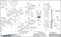
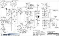
I'm attaching schematics for both the 2SW-1 and 2SW-2. The only difference is right at the input for the 'voicing' control.
I have a pair of 2SW-1 with all the original subwoofer circuitry removed. A more modern subwoofer swarm is used instead.
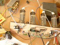
I made a big improvement in reliability by moving all electrolytics & silicon to the rear side of the main PC board (away from the heat of the tubes).
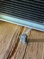
Also the base of the tubes runs way hotter than any other part, don't know why. Almost all tubes that fail will crack around the base like shown in your picture.
I have a pair of 2SW-1 with all the original subwoofer circuitry removed. A more modern subwoofer swarm is used instead.
I made a big improvement in reliability by moving all electrolytics & silicon to the rear side of the main PC board (away from the heat of the tubes).
Also the base of the tubes runs way hotter than any other part, don't know why. Almost all tubes that fail will crack around the base like shown in your picture.
Attachments
Thanks @cvanc I have one of each with only difference being the the input filter.
With your use of the modern swarm subs- do you use an outboard active filter from your preamp to the the bev's and the subs or do you passively filter the bev's and use high level out from your amp to the subs?
Any further mod's to the input of bev's with your removal of the inboard crossover?
Kind Regards,
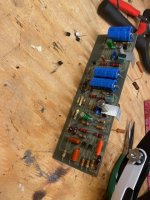
I've moved on and rebuilt both driver input boards. Some bad choices in the past with replacement parts and transistors. Both boards cleaned up and installed.
Next I will move on to removing all the panels vacuuming them and changing the banana jacks on the cabinets. I initially addressed all the panel solder eyelets in cabinets when I could not get consistent measurements - I figured if the panels were done then - no use pursuing further. Replacing those connectors made the difference. This next phase will take a while with life's duties getting in the way.
Next I will move on to removing all the panels vacuuming them and changing the banana jacks on the cabinets. I initially addressed all the panel solder eyelets in cabinets when I could not get consistent measurements - I figured if the panels were done then - no use pursuing further. Replacing those connectors made the difference. This next phase will take a while with life's duties getting in the way.
Attachments
Does anyone have a clear schematic of the 2sw-1 cross over board?
It looks like the input of the driver board has a 0.027 uf cap at the input with a resistor of 47kohm to come up with about 130hz cut off to the panels on their own.
It looks like the quad OP amp on the cross over board tends to the LF pass and the HF is done discretely with transistors. Can anyone explain the operation I can not read my print it is of low quality.
My understanding is the 2 and 2sw-1 input boards are the same. What I want to accomplish is to drive the 2sw1 without the internal crossover and use an active outboard or passively crossover 1st order the input with a small cap to limit the LF to panel. The .027 seems about right on its own.
Thanks.
- Home
- Loudspeakers
- Planars & Exotics
- Beveridge 2SW-2 Rebuild