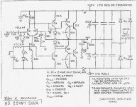
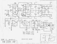
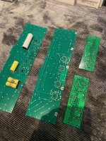
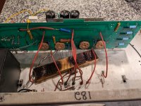
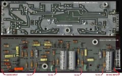
Attached are the drawings I have for the 2 sub boards.
One makes the unregulated rails & has a 50 Watt(ish) woofer amp. The second board is the low level XO and regulators for the opamp rails.
In my amps these boards, and their dedicated power transformer, are removed. My rear panel RCA jack is wired directly to the driver board input. The value of C101 has been increased to make it broadband. All control is upstream via DSP.
Attachments

Thanks @cvanc- This is a much better quality print than what I had found. I am going to first try to passively cross over the panels 1st order at about 100hz and use a pair of powered subs. I use this approach with my model 3's that have been converted to direct drive and it works really well. I have an active crossover as well to try.
The internal sub amp and crossover will be disabled. Thanks for confirming my approach for now.
Kind Regards,
The internal sub amp and crossover will be disabled. Thanks for confirming my approach for now.
Kind Regards,
Thanks @cvanc - I have run into a snag.
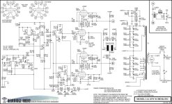
On the phase that includes V203 and V204 I am missing my 1600v a the node indicated as "B" in the circuit diagram. I have the 1600v at the power supply but loose it on the other side of 2.2M ohm R210
I have my 3kv of course
I have pulled off C208 and lifted the 7.5Mohm R3 and the 1.1Kohm R4 but no love.
The other phase is ok.
Something is pulling things down. My components appear to test good but maybe something is happening dynamically or I am missing something very obvious.. frustrating day ..
Attachments
Hmmm, you lost the 1650 on only one 'totem pole'?
But the other totem pole has normal-ish voltages?
That tells me the associated 2.2 Meg resistor on that side is open.
FWIW my two amps are stuffed with 1 Meg in all these locations, not 2.2. I've never found why this value was varied.
But the other totem pole has normal-ish voltages?
That tells me the associated 2.2 Meg resistor on that side is open.
FWIW my two amps are stuffed with 1 Meg in all these locations, not 2.2. I've never found why this value was varied.
Hi @cvanc,
I wish it were that simple. Already tried and tested for the 2.2M resistor. Something is loading it down- I should be more specific it is not 0 volts but a few hundred. I've lifted C208 and R3&4 but no dice. I will keep on looking . There is not much left but the cathode bias cap and resistor. I ve ordered new varistors but the one there tests good.
I did have a flare up in a tube before this happened ... but to be honest I don't think I check anything but the the 3.2kv and 1.6kv prior to that.
More to come and I am open to ideas. I am away for a few days but will back at it over the weekend.
Thanks
The resistors do not load the amps at all... so the only thing that can cause a voltage difference (other then a short) is the tube current (bias). The output impedance of these amps should be less then 1kOhm so a 1M or 2M resistor doesn't change anything here even when connected to ground. The reason that these resistors are placed is to charge the transducers equally before the tubes conduct (this because the coupling capacitors are not yet charged at power-up) Also the feedback loop is dc coupled so it keeps it stable at power up or if a tube is failing.Hmmm, you lost the 1650 on only one 'totem pole'?
But the other totem pole has normal-ish voltages?
That tells me the associated 2.2 Meg resistor on that side is open.
Last edited:
I have solved this problem - 50% self inflicted.Thanks @cvanc - I have run into a snag.
On the phase that includes V203 and V204 I am missing my 1600v a the node indicated as "B" in the circuit diagram. I have the 1600v at the power supply but loose it on the other side of 2.2M ohm R210
I have my 3kv of course
I have pulled off C208 and lifted the 7.5Mohm R3 and the 1.1Kohm R4 but no love.
The other phase is ok.
Something is pulling things down. My components appear to test good but maybe something is happening dynamically or I am missing something very obvious.. frustrating day ..
There is a jumper on the input board that connects 2 ground planes together- it was muddled at some point and connected with PVC wire that was burnt and ugly. I replaced it with buss wire in a teflon tube and soldered it back where it was.
It was originally the wrong location and I simply replaced it back in the same location. It grounded a node on the board that should not of been and it is connected to the amp board and pulled everything down.
So , carelessness on the previous "tech" and carelessness on my behalf. I was focused on the amp board and carbon tracking or shorts.
Trust in no one. lol
Moving on.
Hi @cvanc ,
Thanks for checking in and all the support thus far. Yes, after being stumped for a while- and finally getting that corrected- both amps are behaving. I am about ready for testing on the panels.
At this point, if they work out, I think I will change the tube sockets as the one's in there are pretty loose. I was able to find some NOS type identical to the originals on ebay. Socket changeout will be a job and a half.
I also removed each panel from the cabinets vacuumed them and in one case the lead fell off the stator- I had to grind back the epoxy find the wire and re-attach, The repair looks good. I also took the time to change all the eyelet connectors - they were corroded or in bad shape, Finally I changed the panel banana connectors on the plate as they looked worse for wear. That whole exercise was a ton of work. I am not sure what would be done today but the arrangement of screwing in the panels to the cabinets with spacers is really a pain in the butt. There has to be an easier way.
Next I will probably disconnect the crossover and sub amp and go direct to the input board for a passive first order cut off to the panels of about 100z.
Getting very close.
If you are happy with your new sockets then the best way is to cut away the old ones and desolder the bits that are left on the PCB. This will give the least stress on the board.
"If you are happy with your new sockets then the best way is to cut away the old ones and desolder the bits that are left on the PCB. This will give the least stress on the board."
Yes, for certain, although the boards were in relatively good shape for 40+ years old-- the trouble shooting and previous work played hard on them. So, one pin at ta time is the way to go. Between soldering and de- soldering - only 96 connections to go! 🙂
Yes, for certain, although the boards were in relatively good shape for 40+ years old-- the trouble shooting and previous work played hard on them. So, one pin at ta time is the way to go. Between soldering and de- soldering - only 96 connections to go! 🙂
STOP STOP STOP
Here's where you get to learn about those Mother-effing tube sockets.
One of the main failure modes for Beveridge amplifiers is 'tube droop'. The tubes are held horizontal and eventually they just fall out of the socket from their own weight. When the pins open up it's spark city and things fail.
Further, and here's some new data for you, the bases (pin end) of the tubes are much hotter than the rest of the tube, in my rig anyway.
So kill 2 birds with one stone - replace the sockets with individual machined pins like those used in a Nixie clock or some such. I bet it would be a tighter contact, plus open airflow right where you need it is always a help.
It's a real project getting old sockets off. You will damage the board even if carefully removing contacts one by one. The boards are fragile and the foils are fragile.
in case you will disgard the old sockets just cut them with a plier. No de- soldering of the entire socket. Just the left over pins. Much easier end it will save your board.
Attachments
Yes--- snipping the bakelite sockets is the way to go.
I mis-remembered.. I ordered sockets here @ $3each. Same Mfr. as original.
https://www.surplussales.com/Tube-Sockets/TubeSkts-3.html
Better hurry they only have 6,400 in stock. lol
I will investigate @cvanc suggestion as well before I embark on the next session with these amps.
I love that we are able to discuss keeping these antiquities alive and that someone, in the future , will have a record of these efforts to help.

My project has stalled as use the summer here to take advantage of the weather and other outdoor activities.
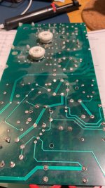
@cvanc and I have been trading emails and he has helped tremendously with some questions. My amp units have been refurbished totally and work on the bench. I have done maintenance on the panels, cleaning, new connectors , and new banana sockets etc. Also corrected an error that the previous tech accomplished that I duplicated and frustrated myself for weeks.
In the meantime - I had mentioned that I did not attack the tube sockets as the boards are in good shape but the foil is fragile and I know that the socket removal will be a ton of work and hazardous to the foil. The current sockets are loose and "functional" but no amount of tightening in this state will work or is permanent. The hazards of loose connections on this design could be catastrophic.
@cvanc has hooked me up with the design of new boards masked and plated through holes- this is a major improvement I am grateful.. I will be populating the boards shortly as I have assembled all the necessary duplicate components. I will have the originals as spares and the new ones will go in the amps. Getting HV components in small quantities is difficult from 1 source. The usual suspects of Mouser and Digikey have limited selection. Ebay, Surplus Sales of Nebraska I also went direct to Caddock for some HV resistors.
This opportunity has opened up questions for better filtering of totem poles --after all, there is only about 10uf per pole with the caps in series. .
On more filtering how much is too much given the fragility of the transformers and capacity of the current rectifiers? The HV diodes I have are 6kV and 200ma. I have some that are 1a and 6kV but the form factor is really too large for the boards - I could make them work.
@cvanc has some good ideas for protecting the boards and transformer and has upped the filtering banks. Hopefully, he will chime in to offer his solutions here for the benefit of all
Last point on transformers. Let's get specific with exact model replacements for HV, heater and pre-driver board. I have to check my notes - I think I measured just under 1100v for the HV before the doubler unloaded. If someone ever has to replace a transformer lets hear specific suggestions.
my rectifiers in use and working DO-15 package :
https://www.mouser.ca/ProductDetail/Diotec-Semiconductor/HV6?qs=OlC7AqGiEDmikVIh00K6tw==
Alternative D7 package :
https://www.mouser.ca/ProductDetail/Diotec-Semiconductor/BY6?qs=OlC7AqGiEDngOM3wfJTVnw==
Attachments
Kcin I'm glad you've got both amps running! A major accomplishment.
Here's what you need to know: Keeping them running is hard!! So, with that in mind...
Adding transformer protection:
The amps as designed do not protect the transformer from inrush current and they do not protect the transformer against tube failures. No wonder they have a reputation for failing. I highly recommend all of these:
1) Do the membrane bias mod!
2) Add inrush limiting at power-on
3) Reduce the AC line fuse value as much as possible - I run a smaller than original fuse no problem!
4) Change that 200 Ohm 10W resistor to something that will function as a fuse during tube failures
5) Beef up the HV rectifiers so they survive tube failures
Undoing heat problems:
All 3 screen grid supplies are a huge weakness due to heat proximity and failures are spectacular. You MUST move 3 diodes & 3 electrolytics to the back of the board! I'm OK with a 1N4007 here; I used one of the same diodes I got for the HV string. I fit the biggest electrolytic that fit the lead spacing, IIRC... 270u/160V
Expanding on this idea I eventually moved almost all of my parts to the back side and not one of them has failed since.
Undoing tube socket problems:
"Perfectly good tube fell out of the socket" is failure mode Number One, folks!! And what fun it is when it happens. The transformer has seconds to live unless you do something about it.
You can coexist with the sockets as long as you do two things:
1) It's not at all hard to re-tighten the socket contacts with a dental pick & a flashlight. This is what I do and I'm a Ninja at this by now lol. But I have open fan holes so access is easy.
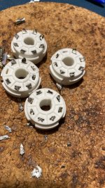
2) ADD TUBE SUPPORTS so the tubes simply can't droop. I use a piece of wood but yeah I don't recommend it - see photo. I recently got some ceramic standoffs and will put them in soon.
The Utopian ideal is individual machined pins instead of a socket, but work is needed to sort out exactly what would fit.
Undoing tube failure problems:
Repeated tube failures will eventually destroy the HV rectifiers. When they fail the transformer has seconds to live unless we do something about it. I put in an overkill diode string and make sure my fusing is tight so a fuse opens first. I've got three BY228 in series with 10M balancing resistors across each one. Use resistors with a good voltage rating, mine are Vishay VR25.
Beef up the components at the midpoint of each 'totem pole' of tubes. In my experience the Varistor is critical, attached is what I use. I got the 2.2K resistor up to 7 Watts not because of any insight but because it would fit.
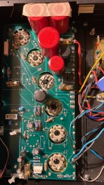
And finally a request: Check for gain binning?
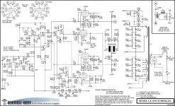
I've always wondered if individual amps had their internal gain custom set to match the cabinet they were shipped with. Can you check 3 resistor values for me? R120, 121, and 122. It's the T shaped group above the 2 side by side 'lytics. If gain is varied by s/n these might be the values they noodle.
That's enough for now, I'll check in on ya from time to time. Good luck and enjoy the results!
Here's what you need to know: Keeping them running is hard!! So, with that in mind...
Adding transformer protection:
The amps as designed do not protect the transformer from inrush current and they do not protect the transformer against tube failures. No wonder they have a reputation for failing. I highly recommend all of these:
1) Do the membrane bias mod!
2) Add inrush limiting at power-on
3) Reduce the AC line fuse value as much as possible - I run a smaller than original fuse no problem!
4) Change that 200 Ohm 10W resistor to something that will function as a fuse during tube failures
5) Beef up the HV rectifiers so they survive tube failures
Undoing heat problems:
All 3 screen grid supplies are a huge weakness due to heat proximity and failures are spectacular. You MUST move 3 diodes & 3 electrolytics to the back of the board! I'm OK with a 1N4007 here; I used one of the same diodes I got for the HV string. I fit the biggest electrolytic that fit the lead spacing, IIRC... 270u/160V
Expanding on this idea I eventually moved almost all of my parts to the back side and not one of them has failed since.
Undoing tube socket problems:
"Perfectly good tube fell out of the socket" is failure mode Number One, folks!! And what fun it is when it happens. The transformer has seconds to live unless you do something about it.
You can coexist with the sockets as long as you do two things:
1) It's not at all hard to re-tighten the socket contacts with a dental pick & a flashlight. This is what I do and I'm a Ninja at this by now lol. But I have open fan holes so access is easy.
2) ADD TUBE SUPPORTS so the tubes simply can't droop. I use a piece of wood but yeah I don't recommend it - see photo. I recently got some ceramic standoffs and will put them in soon.
The Utopian ideal is individual machined pins instead of a socket, but work is needed to sort out exactly what would fit.
Undoing tube failure problems:
Repeated tube failures will eventually destroy the HV rectifiers. When they fail the transformer has seconds to live unless we do something about it. I put in an overkill diode string and make sure my fusing is tight so a fuse opens first. I've got three BY228 in series with 10M balancing resistors across each one. Use resistors with a good voltage rating, mine are Vishay VR25.
Beef up the components at the midpoint of each 'totem pole' of tubes. In my experience the Varistor is critical, attached is what I use. I got the 2.2K resistor up to 7 Watts not because of any insight but because it would fit.
And finally a request: Check for gain binning?
I've always wondered if individual amps had their internal gain custom set to match the cabinet they were shipped with. Can you check 3 resistor values for me? R120, 121, and 122. It's the T shaped group above the 2 side by side 'lytics. If gain is varied by s/n these might be the values they noodle.
That's enough for now, I'll check in on ya from time to time. Good luck and enjoy the results!
Attachments
"Membrane bias mod"
If you are using the 200 Ohm resistor R212 as a fuse you need to make sure when it opens up the amp shuts down calmly and the membranes aren't disturbed. Unfortunately it doesn't happen that way unless you make a change.
The positive stator is biased positive by resistor R208. The supply end of R208 needs to be moved upstream of the 200 Ohm resistor, it is currently connected downstream.
This change keeps both stators biased normally when a tube fails and the 200 Ohm resistor opens. Without modification, the positive stator shuts off and the negative stator keeps running , which slams the membrane hard over to one side. Very stressful and definitely to be avoided.
Also, I just put in these ceramic standoffs for tube droop and they look real good https://www.amazon.com/dp/B0951YCQP4?th=1
Attachments

- Home
- Loudspeakers
- Planars & Exotics
- Beveridge 2SW-2 Rebuild