Kcin I'm glad you've got both amps running! A major accomplishment.
Here's what you need to know: Keeping them running is hard!! So, with that in mind...
Adding transformer protection:
The amps as designed do not protect the transformer from inrush current and they do not protect the transformer against tube failures. No wonder they have a reputation for failing. I highly recommend all of these:
1) Do the membrane bias mod!
2) Add inrush limiting at power-on
3) Reduce the AC line fuse value as much as possible - I run a smaller than original fuse no problem!
4) Change that 200 Ohm 10W resistor to something that will function as a fuse during tube failures
5) Beef up the HV rectifiers so they survive tube failures
Undoing heat problems:
All 3 screen grid supplies are a huge weakness due to heat proximity and failures are spectacular. You MUST move 3 diodes & 3 electrolytics to the back of the board! I'm OK with a 1N4007 here; I used one of the same diodes I got for the HV string. I fit the biggest electrolytic that fit the lead spacing, IIRC... 270u/160V
Expanding on this idea I eventually moved almost all of my parts to the back side and not one of them has failed since.
Undoing tube socket problems:
"Perfectly good tube fell out of the socket" is failure mode Number One, folks!! And what fun it is when it happens. The transformer has seconds to live unless you do something about it.
You can coexist with the sockets as long as you do two things:
1) It's not at all hard to re-tighten the socket contacts with a dental pick & a flashlight. This is what I do and I'm a Ninja at this by now lol. But I have open fan holes so access is easy.
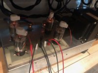
2) ADD TUBE SUPPORTS so the tubes simply can't droop. I use a piece of wood but yeah I don't recommend it - see photo. I recently got some ceramic standoffs and will put them in soon.
The Utopian ideal is individual machined pins instead of a socket, but work is needed to sort out exactly what would fit.
Undoing tube failure problems:
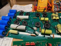
Repeated tube failures will eventually destroy the HV rectifiers. When they fail the transformer has seconds to live unless we do something about it. I put in an overkill diode string and make sure my fusing is tight so a fuse opens first. I've got three BY228 in series with 10M balancing resistors across each one. Use resistors with a good voltage rating, mine are Vishay VR25.
Beef up the components at the midpoint of each 'totem pole' of tubes. In my experience the Varistor is critical, attached is what I use. I got the 2.2K resistor up to 7 Watts not because of any insight but because it would fit.
And finally a request: Check for gain binning?
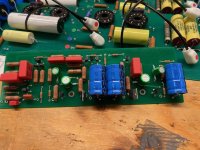
I've always wondered if individual amps had their internal gain custom set to match the cabinet they were shipped with. Can you check 3 resistor values for me? R120, 121, and 122. It's the T shaped group above the 2 side by side 'lytics. If gain is varied by s/n these might be the values they noodle.
That's enough for now, I'll check in on ya from time to time. Good luck and enjoy the results!
In my examples R120,121 are 1k2 and R122 is 6k8
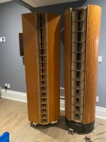
After months of back and forth on the bench I finally got around to connecting the Beveridges up today to put some signal through them.
On the bench they did confound me a couple of times. My first attempt this past weekend of hooking them up was unsuccessful and more bench time.
Today they sang!
A couple of minor problems- one amp has some white noise but plays well. It may be one of the transistors... I will have to investigate and perhaps swap input boards and narrow it down. Further, One of the panels was popping on loud passages- however, I discovered that the stator wire insulation pulled away on one panel and was arcing to the the frame... I fixed the wire and will have to re-install the panel. I am fairly confident that is the problem.
I picked these up in January and was discouraged by them most of the time as they posed various challenges... many as the result of previous owner(s) past interventions.
I am pretty pleased that I was able to save these.

You are going to need to clean the ESL panels. You must remove each panel from the cabinet and clean both sides. If the grill foam is missing and the lens is exposed you can bet the front side of the panels will be filthy.
The is a delicate operation as the epoxy stators are crazy brittle and crazy fragile. I cleaned mine with a vacuum and (gentle) compressed air.
While out you can inspect the membranes on both sides. Look for areas where the metallization is eroding away.
Also... sounds like it might be time to buy a nice measurement microphone if you don't already have one. I have the UMIK-2 and highly recommend it.
Wiring inside the speaker cabinet:
This is all high voltage wire, of course. It is stiff and brittle from age and is best replaced. I used some nice limber HV wire with silicone insulation. It was rated at 15KV, more than enough.
Different generation panels have different terminals. Some just have stubs of bare wire sticking out from the corners. Extremely delicate, careful here!
And if you take a look, you should find a single bare wire running around the entire inside of the cabinet. It connects to both of the metal posts the amplifier mounts on. I have no idea what it's there for.
The banana plug interface needs careful attention. Dirty and arced and just plain beat up parts should be replaced.
Physical alignment of the male bananas to the females on the amp chassis is lousy!! They do not mate fully, not even close.
I solved this with flexible mounting of the females in the amp, and every time I mount an amp I push each banana further down with a tool to make sure it is fully seated. A glue called "E6000" is perfect here.
Hi Carl,
The panels were all cleaned and vacuumed meticulously. The arcing in my case was clearly observed on one panel where the wire teflon sheath for the front stator of one panel slipped and bare wire was in close proximity to the grounded frame. I fixed that and will re- install the panel tonight.
The stators are indeed brittle- where the stator wire comes off front and back - wire broke away in one instance and I had to grind back with a dremmel and re-solder some high tension wire for that panel. Last night I taped around the arcing panel wire whose insulation slipped for the repair and in pulling the tape off---off came some expoy material and the wire in semi free space--- I re-affixed that too and the panel is ready to go back
The wire around the box is to ground any potential arcing that could accidently happen in the enclosure and drain it to the amp chassis- quad ESLs have a similar arrangement.
I changed all my female and male banana connectors on the amps and speakers respectively- some were blackened and tarnished -they are now pristine.. Although, your are correct they don't at all mate fully amp to cabinet... I'll have to assess.
The white noise I hear is limited to the one amp - not the speaker - I isolated it. So it could be the input transistors, funky resistor or maybe the god awful drooping tube sockets or tubes. I will have to work further on that. I may fully disconnect the low level side and see if it is the amp board vs the input board.
On my model 3's the deposited foil is about the same as on these model 2's mostly shiny with a few specs of dull spots. I have "new" material purchased from Roger Modjeski- that he evidently had from the Beveridge days and its virtually in the same condition.
Overall both amps and speaker work - for me now it is fine tuning. And that is an accomplishment for me. Once worked out - I will turn my attention to building the new double sided masked boards you set me up with- I have all of the parts now. I did not want to invest more time until I could get these going. ..More to come!
On your noise issue, might want to swap tube sets between chassis to see if you can move the problem to the other side?
It's a bit extreme but not really that hard to swap entire driver boards between frames. Verify it follows a board?
I wonder about the subwoofer-specific boards, I guess they could be noise suspects too? (I have no history here, I took mine out. My rear panel RCA input goes directly to the driver board.)
Hissing might also be breakdown of brittle insulation on HV wire somewhere (including inside the cabinet). Inspect your foam cabinet stuffing for burn marks.
I still have my original driver boards and have not had noise trouble from them but of course anything is possible.
The arcing on the one panel was repaired by re-dressing the wire. That speaker now plays at full volume like its partner- good news. Bad news another stator wire broke off while doing the repair. I had to scrape back epoxy and carefully solder a new wire then re seal with new epoxy... done and finished.
How much noise/hum is typical with these amps?--- I get a little bit but then I am testing wide open chassis with 6' of HV silicon wire between amp on my bench and speaker- that acts like an antenna for sure.
The sockets are terribly loose --- so that can't help. Input/output board and tube set testing for noise hum influence is next. Overall they sound great! The hum/noise is not terrible at all -- its there though.
You will never get these amps to NOT hum.
I have done the usual "audiophile capacitor overkill" and greatly up-sized all the filter and decoupling caps, often to an absurdity just because I had the parts and they fit.
Even so, in my listening room - which I can get pretty quiet - the hum from the speakers defines the noise floor of my room.
A small acoustical hum comes from both my transformers, but by far the main hum comes from the panels.
Thanks Carl, I think given the vintage and the fact that you have a string of only 4 caps in series per phase for about 12mfd of total capacitance plays a little havoc.
A lot of the noise I have discerned is airborne from my long HV test leads and the the fact that the amp is is free space not shielded. One amp has a little more "noise" I am fairly certain now it is the output stage and I will be swapping in tubes to test my theory and see if that helps. The panels thankfully work really well after my repairs.
My model 3's with custom direct drive amps now have a comfortable bedfellow.
Attachments
Sweet stuff, kcin.
In the Bev amp you can turn off the totem poles by opening the 200 Ohm 10W resistor. You can then listen to the panels while driven by only the stator bias supplies. They hum even then!
Here's where we start listing The Hidden Beveridge Flaws and we begin with a doozie. The ripple on the positive and negative stators is not equal and opposite so it does not properly null at the midpoint where the membrane lives. So even when powered by bias alone these make hum.
To give scale I mean put your ear up against the lens in a quiet room kind of hum - but it's perfectly obvious then.
Very true- Amazing really for the time- these would never be able to be reproduced commercially now because of all the little snowflakes that might get electrocuted or something like that lol...
I have a theory about the hum. I think it can originate from the rectifying. so if an inductor + a resistor is placed between the diodes and the capacitor bank, the current spikes could be attenuated. Those spikes induces EMI even air borne. Very often I use this in power amplifiers. In ordinary power amps 0,5 ohms is good.
I was conversing with another Beveridge owner. His concern was oscillation in one of his amps. After many attempts to cure it- he discovered that the filament transformer #3 was coupling noise into the node where the filament and high voltage meet at the cathode. One part of the cure was to use a separate filament transformer for #3, second part of the cure was to remove the very large form factor HV diodes that were radiating EMI - replaced with smaller 250mA HV diodes. This eliminated the EMI. The last part was his inclusion of a 100 ohm carbon comp resistor in between the cathode and the HV node... I still have to look at this and see what he described to me on the schematic.
So coupling of the filament transformers to the HV is possible/likely- this would contribute to noise/hum or oscillation. The dreaded transformer plays havoc again.
With regard to your solution @esl 63 - what size inductor would you use in conjunction with the low ohm value resistor?
So coupling of the filament transformers to the HV is possible/likely- this would contribute to noise/hum or oscillation. The dreaded transformer plays havoc again.
With regard to your solution @esl 63 - what size inductor would you use in conjunction with the low ohm value resistor?
I have not installet inductor yet on my Beveridge 2sw2.
But 20 mH would attenuate the spikes quite well.
But 20 mH would attenuate the spikes quite well.
To all who run Bev amps with no fan at all: I've decided to stop and you should too.
I found a terrific fan; it has nearly ideal curves for "top off" operation and it's stone quiet. Fits the hole perfectly. I'll leave it to reader to work out the needed 12V.
https://www.amazon.com/dp/B00BEZWPTO?psc=1&ref=ppx_yo2ov_dt_b_product_details
I found a terrific fan; it has nearly ideal curves for "top off" operation and it's stone quiet. Fits the hole perfectly. I'll leave it to reader to work out the needed 12V.
https://www.amazon.com/dp/B00BEZWPTO?psc=1&ref=ppx_yo2ov_dt_b_product_details
I had two different fans in my units. One amp had Modjeski's servo control in it.
The one fan in one amp was stone quiet as well--- I tried and returned many fans in pairs -- and none was as silent as the one original. I did end up finding a NOS mate on ebay.
Here is the model:
https://www.nriparts.com/products/imc-ws2107fl-1009-cooling-fans/274397
The one fan in one amp was stone quiet as well--- I tried and returned many fans in pairs -- and none was as silent as the one original. I did end up finding a NOS mate on ebay.
Here is the model:
https://www.nriparts.com/products/imc-ws2107fl-1009-cooling-fans/274397

I am close to finishing of all of the new boards for the Beveridge amplifiers. One input board stuffed today-one more to go. The amp boards are done. These NOS tube sockets have a vise grip on the tubes- that will be welcome considering the old boards almost let the tubes fall out by gravity.
Testing with the new boards will begin soon.
Testing with the new boards will begin soon.
Attachments
- Home
- Loudspeakers
- Planars & Exotics
- Beveridge 2SW-2 Rebuild