SEAS EXOTIC F8 speaker build

There does not seem to be much information from builders using the SEAS Exotic F8 so here goes. Following on from my satisfaction with the Hemp FR8 reflex enclosure I made in March 2021 I wanted to build what I hoped would be an even higher quality one. I settled on the SEAS Exotic F8 for this.

I considered horn and reflex designs for this project but concluded that the closed box would be the best for the present location. The design is basically the 60L closed box in the SEAS data sheet but I altered the dimensions slightly to better suit my den (small room converted from garage).

I drew up the panel dimensions and routing for joints and got all parts cut by a firm specialising in routing sheet materials. The enclosure is 18mm Birch ply with double thickness front and back panels. The bracing is MDF. The reason to get the work done professionally was that the internal bracing has hundreds of holes. I estimated it would take a week working with hole-saw or router and producing huge amount of dust so it was an easy decision. Assembling the speaker then was a pleasant task which took a week to complete. I intended to make it permanently sealed by gluing all parts so I had to make a good estimation of the damping required. I had a lot of light polyester mesh which I judged to be suitable. I put a layer internally behind the cross braces and a layer round the drive unit part of the enclosure. There is some additional thickness from random pads. The enclosure was painted and the front panel varnished before joining the two together. The finish is the same as for the Hemp enclosure. These builds are not regarded as pieces of furniture and I don’t want them to be veneered. They are for use in my den so function is the aim. I am happy with the varnished fronts and the grey painted enclosure. The finish is perfectly acceptable and very easy to do.

The total cost of the speakers was £1650 in June 2021.

The sound was as expected initially very bright and forward and revealing of detail though thin at the lower range. They are very easy to adjust to your liking in situ as the tuning is done by components in the speaker leads. I added an inductor and resistor as SEAS suggest and then adjusted these values after careful positioning of the speakers in the room.
After months of listening I am very happy with them indeed. They are still a work in progress as I can tweak them. I have a few inductors and resistors wired up with switches to allow easy substitutions. I will also make some spiked stands to see the effect.
P1090395.JPG
P1090032.JPG
P1090042.JPG
  • Like
Reactions: Freedom666

Akita "AllInOne" Amp based on TPA325x PFFB+ and LLC PSU in one board.

Hi guys and girls (if any)))))
Many people know my amplifier, low price and good sound. I have a desire to improve it a little more by using high quality components such as OPA1656 opamp, Panasonic caps in power line , and Wima output caps.
Write all desires here.
100-265V AC
Size - 180x90, height ~50mm

My paypal - ledsscp7@gmail.com
group buy closed, the cost of a amplifier is $160 , delivery is 30, depending on the country.

Cardone - 1 + Case+++ Send
leszczu - 1 ++
multisync - 1 ++
vizeta - 1 + Case +++
Vunce - 1 ++ Send
mamocel - 1 ++Send
manniraj - 1 ++ Send
San4 - 1 + Case +++
ElliJ - 1
pinnocchio - 1 ++
audioillness - 1 + Case +++
routhun - 1 ++
Billy Graham - 1 + Case +++
al2813 - 1 + Case +++
Nerone -1 + case +++ SEND
Mission835 - 1 ++ Send
johoya - 1 ++
paproch - 1 ++
Jogi -2 ++


Ordered:
Case, connectors and pots
OPA1656
Ferrites for transfomers and inductors.
Litz wire
Elna Silmic II
All capacitors
Ordered PCB.
TPA3255 and another parts
MOSFET for PSU

Attachments

  • AMP.jpeg
    AMP.jpeg
    306 KB · Views: 6,249
  • AMP1.jpg
    AMP1.jpg
    852.5 KB · Views: 6,341
  • amp2.jpg
    amp2.jpg
    491.5 KB · Views: 5,904
  • amp3.jpg
    amp3.jpg
    666.7 KB · Views: 5,693

Cheap but powerfull PA system!

Hello everyone,

I currently own a very cheap PA System : Devine brand triphonic system (Devine b118a mkii active subwoofer + 2 Devine Trono 12 heads)
In terms of value for money, it's excellent but I would like a more powerful system, with more impact (feel).
I considered purchasing an additional subwoofer, like The box TA18, but I don't think it's ultimately a good idea and I prefer to start with a blank page and a new project.

✅ Budget: 600€ (i already have amplifiers)

✅ Use: Indoors, party with friends, birthdays. Generally 50 people, let's say 100 to gain some margin

✅ Source : a Pioneer DDJ-RR controller, connected to a Behringer FBQ3102HD equalizer. I will buy an active filter.


▶️ What I had imagined:

  • Subwoofers:
(I already have an amplifier : T.Amp TSA1400 (1x1400w / 4ohms))
2 MTH30 with The.Box speaker 12-280-w (250€) or LF12G301 (400€)

  • Heads
(I already have an amplifier : Crown XPX900 ( 2 X 180W / 8ohms or 2 X 300W / 4ohms)
I hesitate between:
  • 2 DIY speakers based on 1 Fane 12-250TC (77€ each + wood and accessories = 100€ / speaker)
  • 2 used speakers (Yamaha S112IV or JBL FRX115, etc... ) (approxiamtively 200/250€ pair)


Looking forward to reading your reviews!
If you have any comments, suggestions, I am open! 🙏

For Sale (Balanced) Iron Pre Essentials Kit + a few components

Hi

I have too many projects and too little time, so I am selling my IP with a few suitable components.

Parts:
  • 16 x UFG1E221MPM (14,64€ - OBSOLET PART)
  • 2 x UHE1V471MHD& (1,88€)
  • 4 x 3296W-200LF (10,66€)
  • 4 x 3296W-1-472LF (10,66€)

All is unused and comes in the original packaging from the store or DigiKey (please see pic)

Cost all together (what is on the pic): 200€ + shipping
Shipping costs by arrangement.
For the time being only EU members (except UK, sorry to much customs paper work)

Links:
Thread: https://www.diyaudio.com/community/...e-register-your-interest.390509/#post-7128942
Store (Sold out): https://diyaudiostore.com/products/iron-pre?_pos=6&_sid=3d084349f&_ss=r


IMG_0486.jpeg IMG_0487.jpeg

What would be the least damaging x-over frequency

If you could put the x-over at any frequency without concern for physical constraints, what would be the least damaging x-over frequency for a 2-way or 3-way speaker?

For example, many speakers cross the tweeter over around 2kHz (just an example- may not be correct) because it works best for the drivers even though the ears are most sensitive to anomalies at that range.

Another example, what would be the least damaging when crossing over a bass driver - 50Hz, 200Hz, or 400Hz?

Leak Stereo 70 question

Hi All,

First post. Hope everyone is well. I am about to start repairing my dads Leak 70 amplifier however he also had my late Uncles Stereo 70 which 'didn't work' - I got this first as a trial run to get familiar with the insides and the schematics, with no risk of any further damage to my dads when Is I start on it. My uncles one was deemed to be gubbed beyond repair, however I noticed very quickly there was no DC voltage getting to it, then noticed that there was no way it could since there was a small bracket thing mounted on the transformer body (3 pin) with a leg going to the transformer and the other leg going to the diodes. There was no connection between the two, so basically it would never work. This was not reflected on the schematic I had or most pictures I could find of the transformer which showed no such 'interruption' to the circuit.

I eventually found an image showing this part and an alternative schematic also showing it, a green part that looked a bit like a high wattage resistor but I assumed it was a thermal fuse. The transformer in my uncles amp had clearly been replaced (also had a date code sticker of the year of his passing) so I think that someone has replaced the transformer but not fitted the part in question. I linked the two pins and hey presto, amp working well and sounding great.

So the question is, what is this part ? Is it a thermal fuse ? If so was this just a bodge to get around UL standards that came out stating transformers had to have one (I think for northern US and Canada), the schematic I have which includes it perhaps refers to it as a Temperature compensation diode? If it is a Thermal fuse, I fail to see how it could ever get hot enough to pop given it is not in contact with the transformer windings (I believe the common way of incorporating these is in the windings. Picture of the missing part attached (the green part).

Many thanks!
Leak-Part.PNG

Paravicini's Solid State Models "312" (Control Centre/Pre-Amplifier) + M100A Mono Power Amplifier - internal Images wanted

On the web there are no internal images to find.
Thank you for upload.

Some URL's:
https://www.enjoythemusic.com/magazine/equipment/0502/paravicini312.htm
https://www.technologyfactory.eu/en/ear/preamplifiers/ear-paravicini-312/a-3052-10000191
https://www.hifinews.com/content/paravicini-312-preamp-and-m100a-monoblocks
https://www.audio-markt.de/market/ear-yoshino-paravincini-m-100a-paravincini-312-374157086
https://www.stereophile.com/solidpoweramps/earyoshino_m100a_monoblock_power_amplifier/index.html
https://www.diyaudio.com/community/...former-coupled-single-ended-amplifier.391567/ (#3-5)
https://www.diyaudio.com/community/threads/o-h-schade-1938-meets-mosfet.144105/ (#20)

under
https://de.scribd.com/document/7199624/Paravicini-312-Control-Centre-Large-Memory
there is to read this:

The Paravicini 312 Control Centre
For over 20 years, Tim de Paravicini’s EAR brand name has been associated with valve amplifiers of legendary quality and reliability. Classics such as the 500-series power amplifiers, the 802 preamp, and more recently the V20 integrated and the 800-series ‘Enhanced Triode Mode’ models are among the most prestigious hi-fi products ever made and have attracted praise and awards the world over.

Although Tim de Paravicini has been designing transistor-based circuits since the days of the very first commercial transistors, he has never before produced a solid-state amplifier under his own flag. But now, after years of breaking with everyone else’s traditions, he has broken with his own and produced the 312 Control Centre, a fully-featured preamp which redefines the world of solid-state just as EAR amplifiers have done for the world of valves.

Taking into account the current growth in the number of sources in many hi-fi systems, the 312 offers no less than eight inputs, three of which are balanced and transformer-coupled. What’s more, there are six outputs: three each balanced and unbalanced, and because they are also transformer- coupled it is perfectly possible to use both types simultaneously (for instance in multi-amped systems) without upsetting the balanced outputs. This means that six stereo power amplifiers can be driven at once.

As you would expect from an EAR product, the phono input also features transformer coupling for moving coil cartridges, ensuring the lowest possible noise, and in order to ensure very high overload headroom and complete stability the RIAA equalization of the phono stage uses an inductor in a unique EAR circuit configuration.

The basic amplifying circuit uses just three transistors in a single-ended configuration, a ‘valve-like’ approach that harnesses the gain of the transistors in such a way as to give sound of unequalled sweetness and clarity. Complete compatibility with other equipment is achieved through the very high input and output headroom of all circuits, plus their low noise.

Again drawing on de Paravicini’s expertise in the field of transformers and inductors, the power supply uses a choke input filter to give very low noise and ripple, and very low dependency on the purity of the incoming electricity supply: it also generates very low levels of interference on the household supply without requiring any additional suppression components.

Simple and intuitive operation has always been a feature of EAR products, and to this end the 312 uses a very high quality and high accuracy volume control with a conventional single-turn range, in conjunction with a unique meter-like scale which clearly indicates circuit gain. Channel balance is maintained to close tolerances right down to whisper-quiet levels.

Finally, it should be hardly necessary to mention that like all EAR products the 312 is built to the highest standards and immaculately finished so that it
looks as good as it sounds. It will set standards for a long time to come.

Attachments

  • m_3052.jpg
    m_3052.jpg
    52.9 KB · Views: 99
  • 71073a.jpg
    71073a.jpg
    161.7 KB · Views: 90
  • 71073.jpg
    71073.jpg
    74.4 KB · Views: 101
  • ear-paravicini-312_3052_1.jpg
    ear-paravicini-312_3052_1.jpg
    31.9 KB · Views: 94
  • ear-paravicini-312_3052_3.jpg
    ear-paravicini-312_3052_3.jpg
    48.8 KB · Views: 102
  • 71073f.jpg
    71073f.jpg
    162.1 KB · Views: 92
  • 71073e.jpg
    71073e.jpg
    209.3 KB · Views: 88
  • 71073d.jpg
    71073d.jpg
    196.3 KB · Views: 91

Bamberg Audio Closing

I received the below email today. I still own, still love, the S5-MTM standmounts I purchased in 2005. They have been in daily use ever since. They sound amazing!

Bamberg Audio, "Speakers For Life", indeed. Thanks for everything, Phil, best of luck in your retirement:

Hello all,
I have decided to retire my efforts with Bamberg speakers. Thank you to everyone who has purchased any of my designs, and for the support and positive feedback you provided me with over the years.

To this end, I have just three sets of speakers left in stock, and they are listed on the Sale Page.

The website will end on April 30, 2024. But you may reach me directly at pebamberg@gmail.com.

With respect and appreciation,
Philip Bamberg


ADKq_NYdvmidox3Tcz_tY9II2e3S-FGnb-0-GQeY3w9S8ePZmWxzcFdrJd3e6gN_ZpT-cttFYlntrR6VtahTsc_SZFN-cEAk32sTUARL3NaTBFfVBVY8NySAcJoUmbwrePEPRkYw8n8qTKBnb0FXMnK8EGFIO9vFlI3VMIE=s0-d-e1-ft

http://BambergAudio.com

Bamberg Audio on Facebook

Sale page

  • Like
Reactions: Pallas and bwaslo

5" Intermodulation Distortion Testing

Another IMD (Intermodulation Distortion) test. The first in the 5" driver size. I will be comparing the Sb Acoustics SB15CRC30-4 with the Wavecor SW146WA01, these measurements have been made under the same conditions as my other tests done in 14 liters such as the slighter larger 6-7" tests https://www.diyaudio.com/community/...ootout-purifi-anarchy-plus-maybe-more.371979/

The Sb Acoustics SB15CRC surprised me with how crystal clear the midrange is, this showed up in measurements and in listening tests. The Sb had one of the cleanest three tone tests at 800 hz of 20 drivers (only surpassed by a 8" Purifi, but out performing a Magico midrange). With music, I noted in songs that had duets that you could pick out the singers individually as opposed to a kind of a combined vocal that comes out of most drivers.

The Wavecor SW146 also did very well in some of the tests especially the 60 and 144hz bass IMD test. The Wavecor has a low loss suspension and will give a good punch to a kick drum. However, having tested the very slightly larger SW182 (see size comparison in attached photo) I do prefer that one for cleaner deep bass output.
Testing conditions are as follows: The test enclosure is a .5 cu ft (14 liter) sealed box with the bottom lip of the speaker just 2 inches above the floor. The microphone is on a stand 49"high with the base of the microphone 33" from the driver. A distance of about 1.5m from the speaker to the microphone. As I'm not measuring in an anechoic chamber my measurements are not comparable to anyone else's but comparisons can be made between the drivers I test.
For information about how to read the graphs see here: https://www.facebook.com/.../posts/1938870303135464/...

As always, I'm open to feedback and driver testing suggestions.

Attachments

  • 3IMD150hz70dbSvW.jpg
    3IMD150hz70dbSvW.jpg
    147.9 KB · Views: 201
  • 3IMD150hz80dbSvW.jpg
    3IMD150hz80dbSvW.jpg
    176.4 KB · Views: 177
  • 3IMD300hz70dbSvW.jpg
    3IMD300hz70dbSvW.jpg
    143.5 KB · Views: 167
  • 3IMD300hz80dbSvW.jpg
    3IMD300hz80dbSvW.jpg
    143.4 KB · Views: 161
  • 3IMD300hz90dbSvW.jpg
    3IMD300hz90dbSvW.jpg
    148.7 KB · Views: 161
  • 3IMD800hz80dbSvW.jpg
    3IMD800hz80dbSvW.jpg
    137.9 KB · Views: 147
  • 3IMD800hz90dbSvP.jpg
    3IMD800hz90dbSvP.jpg
    152.3 KB · Views: 152
  • IMD40hz70dbSvW.jpg
    IMD40hz70dbSvW.jpg
    176.3 KB · Views: 134
  • IMD60hz80dbSvW.jpg
    IMD60hz80dbSvW.jpg
    130.5 KB · Views: 126
  • IMD60hz90dbSvW.jpg
    IMD60hz90dbSvW.jpg
    153 KB · Views: 128
  • IMD75hz80dbSvW.jpg
    IMD75hz80dbSvW.jpg
    141.9 KB · Views: 178
  • IMG_5189.JPG
    IMG_5189.JPG
    320.6 KB · Views: 170
  • IMG_5458.JPG
    IMG_5458.JPG
    338.8 KB · Views: 195

Fan inside audio chassis: variable speed, temperature controlled, analog - No PWM

Many diyAudio projects generate significant amounts of heat, particularly the ones which operate in Class A. Builders work very hard to get rid of this heat, most often by using the largest heatsinks they can find. However, this approach only cools the exterior of the chassis; the air within the box is usually not cooled by active means. Builders simply select a chassis with ventilation holes, and hope the arrangement will be adequate.

On the other hand, there are many DIYers who believe: why build it safe when you can instead build it extra safe? "More cooler is more better"; you can never have too much heat removal.

I decided it would be a fun project to create an active cooling fan for the interior of an audio chassis. A sensor (NTC thermistor) measures the temperature of the air inside the box, and this continuously varies the speed of a DC fan. When the interior air is very hot, the fan spins at its maximum speed, cooling the interior as much as possible. On the other hand, when the interior air is quite cool, the fan spins at its minimum speed, since no cooling is needed. At in-between temperatures, fan speed smoothly varies from slowest to fastest. It's a continuous, analog, quantity.

Since fans also create unwanted acoustic noise, this scheme keeps the fan as quiet as possible while still doing its necessary job. When the interior air is cold there is no need for cooling and no need for fan noise; this circuit slows down the fan to minimum speed. When the interior air is hot, the fan speeds up and makes more noise, while preventing the electronics inside from damage due to overheating. It's only loud when it's preventing disaster.

A fan control circuit using a 24V DC power supply seemed like a reasonable choice. 24 volts is a good match to quite a number of Class A amplifier projects here on diyAudio, which all run on ~ 24V supplies, including several First Watt designs such as ACA, F5, Aleph J, M2, etc. The 24V DC fans themselves are plentiful and cheap: not only does Mouser carry them, so do DigiKey, AliExpress, eBay, and Amazon. You can use a "2 wire" or a "3 wire" or a "4 wire" fan with this all-analog circuit. It only connects to two of the fan wires: red and black. All other fan wires are left unconnected and floating.

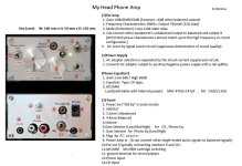
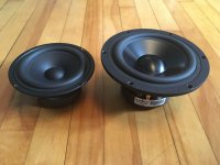
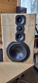
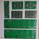
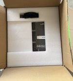
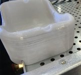
For experimental purposes, I bought three 24V DC fans from Mouser.com, shown in Figure 1 below. Connecting them to a lab power supply, I measured the minimum voltage required to guarantee each fan would start spinning from a dead stop. Below that voltage, a stationary fan "stalls", and fails to begin spinning:
  • 40mm fan: starts reliably at VCC >= 6.3V
  • 60mm fan: starts reliably at VCC >= 8.1V
  • 92mm fan: starts reliably at VCC >= 7.9V
Thus it seems that many 24V fans will be happy as long as the analog control circuit never gives them less than 8.1V (34% of their 24V nominal supply). I decided to add a little margin-of-safety and so I set the Vmin to 37% of the supply. If you hate this decision you can redesign as discussed below (zener diode section).

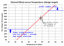
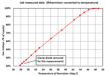
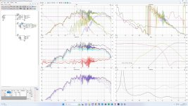
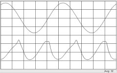
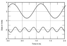
My answer to the question "How Hot Is Too Hot" is shown in Figure 2. This is the design target I chose, shown in red. I've tried to make an analog fan controller circuit which actually implements the red curve in Fig 2, as closely as possible

The fan voltage hits 100% when the thermistor reaches 45 degrees C. In my circuit design the fan voltage cannot exceed 100% of the supply, so further increases in temperature do not cause further increases in fan voltage. This is shown by the dotted blue horizontal line at top right.

At about 30 degrees C the fan voltage has fallen to 37% of the supply voltage. Then a zener diode in the circuit prevents it from falling any further, so the fan voltage remains at 37% even when the temperature falls well below 30C. The horizontal blue line at bottom left shows this effect. The zener diode's spec is (100-37 = 63%) of 24V, namely, 15.1V. Buy a 1N5929B and be happy.

If you remember algebra from school, you know there are several ways to define the red straight line on Figure 2. I choose to define it this way:

  • The line MUST pass through the Anchor Point at (39 degrees C, 75% fan voltage)
  • The slope of the line is 4.2% per degree C

Other designers might choose other ways to define the red line, and that's okay with me. This is just the definition I happen to prefer.

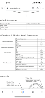
For the temperature sensor, I chose an NTC thermistor made by Vishay. Mouser.com has tens of thousands of these in stock, even in Portugal and Finland. It is Vishay part number NTCLE100E3104JB0 . Resistance at 25C is 100 Kohms, a relatively high resistance, chosen to reduce self-heating. Vishay's datasheet presents the (nonlinear) equation of the thermistor's (nonlinear) resistance vs temperature response. Here is a summary:


Code:
   Temp  R_thmstr        Temp  R_thmstr    
   ====================================    
    19    132200          40     51750    
    20    126100          41     49610    
    21    120300          42     47580    
    22    114800          43     45640    
    23    109600          44     43790    
    24    104700          45     42020    
    25    100000          46     40330    
    26     95540          47     38720    
    27     91310          48     37180    
    28     87280          49     35710    
    29     83450          50     34310    
    30     79810          51     32960    
    31     76340          52     31680    
    32     73050          53     30450    
    33     69910          54     29280    
    34     66920          55     28160    
    35     64080          56     27080    
    36     61370          57     26050    
    37     58790          58     25070    
    38     56330          59     24130    
    39     53980          60     23220

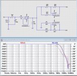
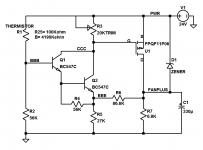
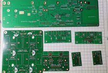
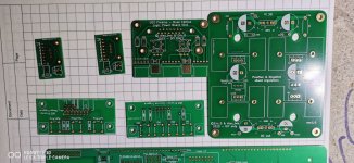
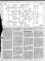
A circuit schematic is presented in Figure 3. The thermistor and resistor R2 form a voltage divider at node BBB. When the temperature goes up, thermistor resistance goes down {it has a NEGATIVE temperature coefficient}, and so the voltage at BBB goes up. The rest of the circuit amplifies and offsets this temperature dependent voltage, then applies it to the fan. When temperature goes up, fan voltage goes up, and so do fan speed and airflow.

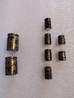
The fan is driven by a P-channel MOSFET called "U1". This allows the circuit to apply all 24 volts of supply across the fan when it's really hot, without any voltage loss due to VCEsat or emitter/source follower drops. Capacitor C1 filters the fan voltage and absorbs any "spikes" that may occur as the fan motor rotates. I selected a special electrolytic capacitor rated for more than 1 ampere of ripple current (Panasonic EEU-FS1V331LB), yet it's in a modest 8mm diameter package. C1 also provides frequency compensation for the negative feedback control loop as a whole.

Adjusting the trimpot R3: let's hit the Anchor Point!

The goal in setting R3 is to make sure the temperature versus voltage curve does in fact pass through the Anchor Point: (39 deg C && 75% of VCC). See Figure 2. To get 39C, a resistor is needed whose value is 53.98 Kohms according to the table above. However instead of 53.98 Kohms, I found very it convenient to simply connect two 27K 1% resistors in series. 54.0K, close enough.

Then I temporarily remove the thermistor, terminal block screw connectors make this easy. I replace it with my 54.0K fixed resistor. To adjust the fan controller's R3 for actual field use, connect the circuit board (and the fan itself!) to the internal 24V power supply network of the audio equipment to be cooled. The adjustment can be performed with the chassis open and its top plate & bottom plate removed, we're not measuring stagnant air temperature just yet.

MEASURE the supply voltage inside the audio gear. It's probably a little bit above or below 24.00 volts. Then switch the voltmeter probes to measure the voltage directly across the fan, and dial R3 up and down. Stop dialling when the fan voltage is exactly 75% of the supply. Done! R3 is now set to the correct value for *this* power supply voltage, and for the device parameters of *this* particular Pchannel MOSFET, on *this* specific fan controller board. Yes, Virginia, two MOSFETS of the same part number really CAN have threshold voltages that differ by two thousand millivolts, just as the datasheets warn. Replace the fixed 54K resistor by the thermistor and its umbilical cable, job done.

A word of caution: this circuit contains so few parts, that each individual part has an effect upon several different aspects of circuit behavior. In other words, everything interacts. Strongly. When designing or redesigning a circuit like this one, it takes a lot of tweaking and adjusting and juggling to get the circuit to work well. Fortunately for you, I have already performed this miserable job; it took me about a half a day to get it completely dialled in. The schematic in Figure 3 works nicely ... but only for THIS supply voltage (24V), and only for THIS choice of thermistor, and it only implements one specific design target curve of Temperature-versus-FanVoltage (shown in Figure 2).

If you want to modify the circuit to operate at a very different supply voltage, or to use a different thermistor, or to hit a different design target T-vs-F curve ... then you will need to tweak and adjust and iterate and juggle component values, to get your new circuit working and meeting your new specifications. It will take effort. Do I know of any time saving procedure(s) for this? Not really; all I can suggest is to thoroughly explore and experiment and keep good notes. And don't forget to have fun!

Fortunately, if all you want to do is change the supply voltage a little bit (for example: use this analog fan controller inside an Aleph J which runs on a 22V power supply instead of 24V), and if you leave all other design goals alone, then you will only need to adjust R3 using the procedure above. Just hit the Anchor Point. I haven't personally tested every single possibility but I do think a simple R3 adjustment is probably all you need, if you keep the power supply voltage within plus or minus 15% of the design value, 24V. That is, (20.4V <= VCC <= 27.6V) only requires a simple twist of R3 to make it work. If you go outside this range, adjusting R3 might be all you need to do, but honestly I would be a little surprised.

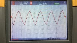
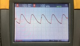
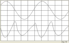
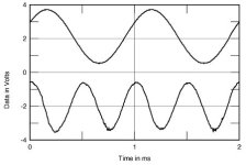
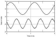
To test out the circuit, I bought some fixed resistors in the range (40K < Rfixed < 80K) and labeled each one with its corresponding Thermistor temperature from the table above. This let me measure the data shown in Figure 4. Eyeballing Fig 4 and Fig 2, it seems to me this design hits the target reasonably well.

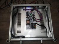
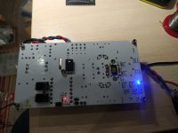
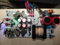
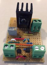
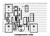
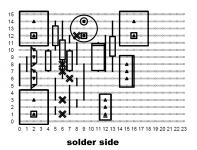
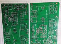
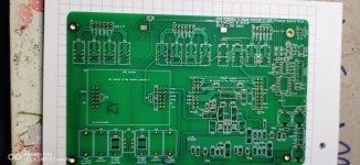
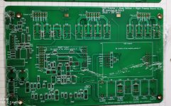
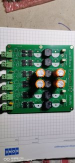
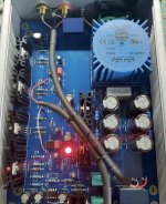
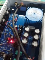
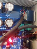
I built the circuit on "Stripboard" sometimes called "Veroboard"; Figure 5 shows a photo. The MOSFET's heatsink is from Tayda, 17mm x 17mm x 25mm, to give me the option of connecting a really high current, high power, high airflow fan ... someday, if I feel like it. The puny little fans in Figure 1 don't actually need an aggressively heatsinked power transistor to drive them. VeeCad cuts-and-jumps CAD drawings of the Stripboard are shown in Figures 6 and 7.

Finally, I suppose I owe readers an answer to the question "Why on earth build this as an analog circuit?" After all there already are LOTS of temperature controlled fan PCBs for sale on eBay and AliExpress and Amazon, at super cheap prices. There are also four hundred budjillion Arduino projects to make a temperature controlled fan.

It's true. There are. Unfortunately, all of these use PWM (pulse width modulation) which commutates the fan between 100% ON and 100% OFF, using digital circuitry. The relatively high-current, relatively fast-risetime digital pulses driving the fan, can couple into other nondigital circuits, creating electromagnetic noise which corrupts low level music signals. Indeed many diyAudio members refuse to include any digital circuitry of any kind, inside their all-analog audio equipment. For them a PWM fan controller is utterly forbidden, therefore an all-analog solution is required. Additionally, some fan manufacturers explicitly state that PWM control of their fans results in greater acoustic noise than analog control, at certain speed settings. Who wants a noisier fan? Nobody.

I should mention that Microchip sells a wonderful family of embarrassingly simplistic non-PWM chips, called MC620/MC621. These implement a bang-bang control system for thermal control of a DC fan, exactly like the HVAC heating and cooling system in office buildings. It's digital, but not PWM. Also, Maxim makes the MAX31740 chip which is a full featured, ultra simple, thermal fan controller using PWM. If you don't hate PWM, check it out. If you are both ambitions and a little masochistic, you could figure out a way to do it with a pair of NE555 timer ICs. Those chips were literally made for PWM.

If you despise PWM, but for some reason don't like the 3 transistor discrete circuit in this message, you could consider designing yourself a new circuit using opamp chips. It's an ambitious project but diyAudio members are brave souls. You'll want ICs that work on 24V supplies, such as LM324 or OP07 or even uA741. Oh and you'll need to pay careful attention to frequency compensation / instability / unwanted oscillation, since opamps have lots of gain while common source power transistors have lots of phase shift. Especially when you decide to keep the deluxe 330uF smoother outer capacitor! You win extra bragging rights if your design does not require or use "single supply" opamps, "rail to rail" opamps, or "over the top" opamps. When you're all done be sure to compare the parts list of your opamp design, against the parts list of this discrete design. I bet you'll find that both need a fan-driving transistor, so the difference becomes (opamps + resistors) versus (two NPNs + resistors). Which is cheaper? However perhaps a circuit with opamps can eliminate the trimmer pot, whose cost is surprisingly high for its mundane function. Have some fun with it!!

_

Attachments

  • Figure_1.JPG
    Figure_1.JPG
    227.9 KB · Views: 1,938
  • Figure_2.png
    Figure_2.png
    35.6 KB · Views: 2,135
  • Figure_3.png
    Figure_3.png
    13.3 KB · Views: 2,173
  • Figure_4.png
    Figure_4.png
    24 KB · Views: 2,102
  • Figure_5.JPG
    Figure_5.JPG
    31.6 KB · Views: 1,776
  • Figure_6.png
    Figure_6.png
    62.8 KB · Views: 1,094
  • Figure_7.png
    Figure_7.png
    56.6 KB · Views: 908
  • Thermal_Fan_24V_schema_in_LTSPICE.asc
    Thermal_Fan_24V_schema_in_LTSPICE.asc
    2.6 KB · Views: 320

Stealing the output from a DAC chip (Topping D30 CS4398)

I have a DAC that sounds very good to me, it's the Topping D30. The chip is the CS4398, a chip that I have listened to in several implementations and always found it very musical.

I would like to try to improve the output stage. I have several ideas in mind (transformers or tubes). As a first step I should steal the analog signal at the output of the chip. Below in photo I show the PCB. The red arrows indicate the points connected to the positive/negative output pins of the two channels.

What do you think is the best way to get the signal? Try soldering the wires to the pins directly? Or act on the four holes indicated by the arrows? In the latter case I guess it is easier, but I don't know how to remove the blue layer covering the conductor. I would be very happy if someone could point me to the right technique.


cs4398.png

Aiwa AA8700 bias adjustment

Hi, I have a problem with adjusting bias on my Aiwa AA8700 amplifier,

Service manual says that you should connect a probe to TP6 ( it is on emitter of Q8) and reach 23mV turning SFR2 potentiometer. The value of that pot. is 100R.
Actually, after warming up, I have like 66mV and turning SFR2 gives nothing ( maybe +- 1mV).
This is on the right channel. On the left channel which is the same I have like only 1mV and also turning a potentiometer has no reaction.
I thought that maybe the pot is broken so i replaced them but no change.
Maybe I should put a bigger value potentiometer ?

Zrzut ekranu 2024-03-17 o 19.23.52.png
This pot is between transistors Q4=2SB648A and Q5=2SD668A maybe they should be replaced but for what ?

There’s also diode D6=STV-4H acting as temperature sensor ( it is attached to heat sink) the diode looks ok, passes the diode test but now that diode can be replaced by a transistor e.g. BC550 + 3K3 and 1k resistors.

What do you guys think I should do ?

Headphone amp for QUAD 405 amp

Hello
Back in the 70s when the Quad 405 power amp was designed, it seems that little boxes were available that amplified the 405 speaker signal output for a headphone output. The box has a switch that either feeds the speaker signal to the headphones or continues the signal to the speakers. The 405 manual has a simple schematic that shows a provisional design.
I thought I would find such a box very easily .. but I have not. Would anyone have an idea where I can find such a thing, preferably as a kit? I am not an audiophile, so I don't need anything very sophisticated.

Many thanks

Audio System in a gym

Hello everyone, I have been asked to recommend suitable loudspeakers for a sound system for a calisthenics room in a gym.
The room is not very large but has quite considerable reverberation.
The amplifier is already present and is a Pioneer (I don't know the model, it is very similar to the a10ae) designed for a home hi-fi system, bi-zone.
As the customer doesn't want to spend a lot, I'd like to know what speakers I could buy to complete the system, he'd like 4 speakers, I have to use the bi-zone so I assume the speakers would need to be 8 ohm. What would you recommend?

USB transport I2S 32bit/384kHz, DSD512, multichannel Out 4xI2S, stereo In I2s, surround up to 16-channels (TDM mode)

There are two of them. They're called Reflex 2.0 & Reflex 3.0
  • Playback of PCM format with a maximum sampling frequency of 762 kHz 32 bit, DSD512 native or DSD256 DoP playback.
  • Playback of S/PDIF - 384kHz
  • Plays multi-channel Surround audio in PCM format.
  • Recording stereo sound with studio quality with a maximum sampling frequency of 762 kHz 32 bit
  • Two I2C ports for controlling external DACs and ADCs
  • Two SPI ports for controlling external DACs and ADCs
  • Addressable LED (Neopixel) control port
  • Thirty two GPIO pins for connecting external controls and indications (potentiometers, buttons, switches, LEDs, encoders)
  • Programmable using ChipStudio, SigmaStudio, PurePathStudio software
  • Hardware adjustments
  • Free change of USB Vid/Pid
  • ASIO drivers from any third-party manufacturers
Sync Modes:
  • Master with internal sync
  • Master with external sync
  • Slave
Possible audio output channel configurations

Configuration
Surround audio
PCM, kHzDSD256
DoP
DSD512
native
44,1
48,0
88,2
96,0
176,4
192,0
352,8
384,0
705,6
768,0
Until
11 289,6
Until
22 579,2
2.0​
++++++++++++
3.1​
++++++++
4.0​
++++++++
5.1​
++++++
7.1​
++++++
12 channels​
++++
16 channels​
++++

Reflex_2_2-часть.jpg


R3_front_800.jpg
R3_back_800.jpg


Ask me!
Oleg
ChipDipDAC
KiCad projects:
Reflex2.0
Reflex3.0

Chip Studio v0.99.5 (19/03/2024)
ChipUpdater_v1.2
firmware Reflex_2.0_v2.4
firmware Reflex_3.0_v2.4

Attachments

  • Like
Reactions: tschrama

For Sale Klein Hummel Telewatt VS56 tube amplifier

For sale is the legendary Klein + Hummel Telewatt VS56 tube integrated amplifier, first model.

Great tube amplifier that is in original condition with all new tubes (4x ECL82, 5x ECC808). They are all measured on RoeTest V10.

Unfortunatelly, I do not have enough room for all this equipment, so it is for sale.

Specs and info:
http://www.tube-classics.de/TC/GermanTubeHifi/Integamps/K+H VS56/VS56.htm
https://www.radiomuseum.org/r/klein_telewatt_vs_56_vs56.html

Price 650€.

Thanks

Attachments

  • 1.jpg
    1.jpg
    304.4 KB · Views: 135
  • 2.jpg
    2.jpg
    603.5 KB · Views: 117
  • 3.jpg
    3.jpg
    482.1 KB · Views: 115
  • 4.jpg
    4.jpg
    308.9 KB · Views: 119
  • 5.jpg
    5.jpg
    357.6 KB · Views: 119
  • 6.jpg
    6.jpg
    282.3 KB · Views: 125

For Sale Gold Note PH-5 phono section

Hi to all,

I have this great phono section for sale. It is NEW, only used for about 15 hours ...

I purchased it to compare it to my DIY tube phono sections to hear the difference because this phono is something that all say is the best buy in the price range of 1000€ and I couldn't agree more. A lot of features, MC and MM section, touch screen, load and gain adjustment 'on-the-fly'. Great value for money.

Link to site:
https://www.goldnote.it/phono-stages/ph-5/

Reviews:
https://www.analogplanet.com/content/gold-note-ph-5-phono-preamp
https://hifiplus.com/articles/gold-note-ph-5-phono-stage/
https://hifiknights.com/reviews/gold-note-ph-5/

I have everything original including package, manual ... just like from the store.

Price: 650€

Attachments

  • 1.jpg
    1.jpg
    277.9 KB · Views: 105
  • 2.jpg
    2.jpg
    296.8 KB · Views: 91
  • 3.jpg
    3.jpg
    576 KB · Views: 96
  • 4.jpg
    4.jpg
    347.8 KB · Views: 93
  • 5.jpg
    5.jpg
    537.7 KB · Views: 96

First HiFi Tube amp

Hello everyone 🙂

I only have guitar amp experience so hifi its the first time, i made a schematic and i'm gonna need help to confirm it if possible:


The first part (The preamp) is an existant project from "diyaudioprojects.com" so this one is ok but i'm not sure about the phase inverter do you see an issu there ?
There is also no feedback do you think i need one and where should it be, around R7 (like in guitar amps) or maybe R4 ?

I made also the first version of the power supply, well its a bit exotic 😆


Thank you for your help
Alexis

A big rock tumbler for aluminum surface finishing?

I'm thinking of getting this big rock tumbler to use in surface finishing aluminum front panels, heatsinks, etc. Prior to anodizing them all at home. I've tried sanding, buffing, lapping on glass, random orbital vs rotary sanding, etc. all sorts of ways, I get good results but not "repeatable" results from piece to piece, especially if I'm progressing through six to eight different grits of sandpaper. I thought well maybe I should get a glass bead blasting cabinet, but thats still a manual operation, and I dont have much room left in the garage. And also its a skill I'd need to learn and you need a very high CFM air compressor for one of those. I certainly dont have room for a large floor standing air compressor. I also looked at vibratory tumblers, but they are expensive and usually use a bowl with a rod down the middle which would mean I cant do long plate stock. The largest ones run close to $2,000

Then I thought I had a brilliant idea (those usually fail me)... Maybe I can find a large sized rock tumbler to do a "set it and forget it" tumble of my aluminum parts so that all the parts of an amp have precisely the same surface finish. The largest size panels I plan on doing would be 12 inches by maybe 9 inches, because that fits nicely in my mini CNC machine. Heatsinks, there are a few I like from heatsinkusa, the 6 inch wide and 4.5 inch wide ones usually cut to 3 inch length. So those are my largest part sizes.

Well, I found this large rock tumbler model which is widely used in the commercial rock tumbling world, it has a 15 inch by 15 inch drum to hold any sort of tumbling media I could think of and also hold the largest parts I'll be making... (link below). It sells for about $850 bucks everywhere and I can drive to pick it up. I'm figuring I could machine all my parts and heatsinks, then simply tumble them for a set number of days, hoping they will emerge from the magical drum with consistently the same and beautiful surface finishes. It's even water tight so I can tumble with wet media, try out different media, walnut shells, ceramic media, 2mm stainless beat shot, plastic abrasive media, corn kernals, etc. Then I'll anodize them (which I am already set up for in the garage).

What do you guys think? Will this work?

https://kingsleynorth.com/65t-heavy-duty-commercial-tumbler.html

For Sale Used Black Gate standard polarized capacitors

ALL SOLD

Genuine Black Gate standard polarized capacitors, all purchased by me from Parts Connexion when they still had stock. Revered by many, reviled by some, my experience with them is that they DO sound better than any modern cap. The leads are short, just long enough to reach through a pcb with matching lead spacing. None of these saw high voltage or excessive heat, used for DC blocking in CD players.

Two large caps shown are 220uF 50v. They measure 209 and 220uF. Lead space is 7.5mm. $10 ea
Four medium caps are 47uF 50v. They measure 40, 42 ,42, and 41uF. Lead space is 5mm. $8 ea
Two smallest caps shown are sold.
Not shown are two brand new caps with full leads, 220uF 4v. They both measure 180uF. Lead space is 2.5 or 3mm. $6 ea

These have been in storage for a while, and I don't anticipate ever using them, so I would like to see some other audiophile enjoy them. I would prefer to sell the entire batch to one person for $50 total, but I could be persuaded to break them up. Add $6 for shipment of any quantity, to USA only.

Attachments

  • 20240325_143110.jpg
    20240325_143110.jpg
    459.7 KB · Views: 125

TI DACx1001 discussion - I2S input, Vref etc

Im planning to build a DAC11001B based DAC and will share any progress here inc. measurements, aiming for uncompromised measured performance from the chips.

First, I wanted to see if the suggested 24bit RJ glue logic for DAC11001 could be adapted to work with a normal I2S input.

After a read of the datasheet, I attempted to simulate it (the first frame of the sim has an error):

Untitled3.png


The DACx1001 wants the audio data left justified to the 23rd bit and an 8 bit shift register will shift the I2S MSB accordingly, sound about right?

Something I'm trying to understand is why the main shift register has 2 inputs held high instead of one.
I think it could be to have a longer LDAC pulse so that the LDAC minimum low time (20ns) is satisfied even at the highest clock rates,
however the shift register output also drives the XOR and it causes the audio data MSB to be inverted.
Untitled5.png


This couldnt be right, so I figured instead the shift register output may be delayed by 1 bit because of some hidden issue in the sim.
If this proposed delay is corrected the input data will no longer be effected, but this changes the register address from DAC-DATA (01h) to DAC-CLEAR-DATA (03h) and this doesn't seem right either:

Untitled6.png


Can anyone clarify this?


Few other small things I managed to figure out about the glue logic circuit that may not be obvious to everyone:
DAC will be sensitive to BCLK jitter, as the LDAC pulse is clocked out of shift register by BCLK.
The circuit should be directly compatible with the 18 and 16 bit versions of the chip.

  • Locked
For Sale TD-124 Turntable (The original series not MKII)

I am selling vinyl related hardware, first up is my old TD-124.

This is what I would refer to as an unrestored but heavily refurbished TD-124. Short of the chassis and motor everything else had to acquired to restore it to running order. Most components are original Thorens, there are some significant improvements.

*The slip platter brake needs pads and to be adjusted to be functional. It does not have the 45rpm integrated adaptor. *

20240310_204559.jpg


This table has its original E50 which I serviced more than a decade ago (and have lubricated periodically). Note that the eddy current brake is adjusted for 120V+ AC mains, and that reduced voltage (110V - 115V) will allow you to ease off on the eddy current brake which results in quieter running.

It has Hanze HI-Fi motor suspension springs, and the an Audio-Silente idler.

1710120693347.png


It has the more desirable Thorens OEM cast iron platter. It is equipped with a Gem Dandy Cork & rubber mat.

Short mp4 files of it running are attached.

20240310_204545.jpg


The wiring to the switch and neon lamp has been replaced.

20240310_194512.jpg


It comes with a plywood plinth mass loaded with roughly 10lbs of lead shot capped off with epoxy. It also comes with multiple arm boards including 2 that are suitable for use with Jelco 12 inch arms like the 750, 850, and 950...

The TD-124 is PICK UP ONLY, and I will accept cash, PayPal Friends & Family, bank transfer, and certified checks in the amount of $850. I am located just a couple of miles south of Boston, MA. I will NOT ship this item. The price isn't negotiable and I am not interested in trades as I am trying to reduce my collection of misfit toys. 😀

Attachments

  • Like
Reactions: dBel84

Help with Fostex’s Newer FE103NV2 Thiele/Small Parameters

Good afternoon everyone. So this is the second set of drivers in this series that Fostex doesn’t really give a lot of info on the Thiele / Small perimeters for this driver. Am missing the following information?

1. Sd
2. RMS
3. Z
4. No %
5. RE
6. XMAX

So what can I buy to get this missing info I need? Here’s a picture from Fostex’s website. Thanks Jeff

Attachments

  • IMG_3464.png
    IMG_3464.png
    126.1 KB · Views: 75

My first passive crossover design!

I recently made a post trying to get some information on how to design a crossover as I had previously no knowledge on how to and wanted to renovate some speaker cabinets and remake a crossover to do this. To inform my design I used frequency and impedance graphs from the manufacturers. I know this doesn't deliver the best results as the boxes used for these tests aren't the same as the one that I'll be using for my speakers. Nonetheless I decided to use them as I don't have the equipment to make my own graphs. Here are the data sheets for the drivers that I used; Bass driver: https://www.farnell.com/datasheets/2623802.pdf , Horn driver: https://www.parts-express.com/pedocs/specs/290-5634--eminence-f110m-8-spec-sheet.pdf and tweeters: https://doc.soundimports.nl/pdf/brands/GRS/DTM-8/DTM-8 Specifications.pdf. Here is the resulting circuit
Screenshot 2023-09-14 210843.png

And the resulting graphs from this
Screenshot 2023-09-14 211000.png

I can tell from the frequency graph that the tweeters aren't doing a lot, now I'm not sure if this is from how I've tried to link them in parallel or how my attempt at a Zobel network has affected the level of these drivers. Or whether it is a good idea to have them connected at all or if I should just use the horn and bass drivers to make the speakers. Any advice on how I can better improve this design or use this design to inform another design would be greatly appreciated!

3-way crossover help

Hello all!

I'm designing a 3-way as a spare time project, in a WMTM alignment. The baffle is 30cm wide, 45cm high and the drivers I have at hand are:

Peerless 830868: https://www.samodelka.ru/pictures/peerless/peerless_830868.pdf
VIfa TC9FD: https://doc.soundimports.nl/pdf/brands/Peerless by Tymphany/TC9FD18-08/TC9FD18-08.pdf
Seas 27TFFNC/CG: https://www.costruireaudio.com/PDF/SEAS/h1406_27tffnc_cg_datasheet.pdf

Made a mock-up baffle (open-backed, so disregard everything under 400Hz or so). and attached the drivers to it. I plan to surface mount the drivers and made a similar roundover to baffle edges as the finished enclosure will have. Made some measurements with UMIK outside, so there's a bit of ambient noise form neighbors and birds etc. Also measured the impedances with DATS. The mids are measured separately. The measurements are at 1m distance, at 0, 22 and 45 degrees, at tweeter height. The height from ground is 190cm on tweeter level. For anyone wanting to lend a hand, they are at this onedrive folder: https://1drv.ms/f/s!AoJmX0yPPNWy6QfpAWANbmA_d65c?e=gFeOVe

Designed for a bit in VituixCAD, and this is the best result I got so far. The phases are quite nicely aligned, the only problem I currently see is that the impedance dips quite low in the 10kHz region, around 2Ohm. The reference angle response is a bit hot but realistically they would be listened to around 10-20degree angle anyway. It's been a few years since my last speaker design/build, and I am rusty as hell. Life tends to get in way of hobbies sometimes 🙂

Would really appreciate if you have any tips and points on perfecting the crossover. Thanks in advance!

EDIT: Updated the onedrive along with VituixCAD sim for 2 mids, measured separately.

Attachments

  • 20240331_112823.jpg
    20240331_112823.jpg
    312.9 KB · Views: 114
  • 3way.jpg
    3way.jpg
    449.8 KB · Views: 87

For Sale UGS - Muse Edition Bare boards

I'm offering a full set of bare boards to build a UGS Muse preamp, including Sala's shunt regulator and power supply , the power supply board is partly assembled. If you are interested please contact me.

1 x UC Board v1.2 / 1 x Left Preamp v1.2 / 1 x Right Preamp v1.2 / 1 x Left Rear v0.0 / 1 x Right Rear v0.0

1 x logic power v0.0 / 1 x trigger amplifier / 1 x trigger inputs / 1 x subwoofer board

2 x UGS Modules v3 / 2 x Buffer Modules / 2 x Encoder Boards / 2 x Salas Shunt Power Supply v1.0

1x External Power Supply v1.0 , including 24 Omron G6S-2 5Vdc Relays

Selling all Boards for 130€ + shipping

The prices do not include PayPal and shipping costs. Shipping from Germany. PayPal is accepted, the buyer pays the additional 5% PayPal fees. Or Payment as Friend than the shipping costs for the EU are 12€ as standard ( PayPal friend) or 23€ by registered mail up to 100gr. Outside the EU it may vary by country. If you are interested send me a PM.

Attachments

  • UGS - Muse Edition (1).jpg
    UGS - Muse Edition (1).jpg
    474.3 KB · Views: 127
  • UGS - Muse Edition (2).jpg
    UGS - Muse Edition (2).jpg
    345 KB · Views: 123
  • UGS - Muse Edition (3).jpg
    UGS - Muse Edition (3).jpg
    300.4 KB · Views: 115
  • UGS - Muse Edition (4).jpg
    UGS - Muse Edition (4).jpg
    518.2 KB · Views: 119
  • UGS - Muse Edition (5).jpg
    UGS - Muse Edition (5).jpg
    279.1 KB · Views: 117
  • UGS - Muse Edition (6).jpg
    UGS - Muse Edition (6).jpg
    425 KB · Views: 109
  • UGS - Muse Edition (7).jpg
    UGS - Muse Edition (7).jpg
    534.7 KB · Views: 112
  • UGS - Muse Edition (8).jpg
    UGS - Muse Edition (8).jpg
    283.5 KB · Views: 115
  • UGS - Muse Edition (9).jpg
    UGS - Muse Edition (9).jpg
    375.8 KB · Views: 122
  • UGS - Muse Edition (10).jpg
    UGS - Muse Edition (10).jpg
    269.7 KB · Views: 117
  • UGS - Muse Edition (11).jpg
    UGS - Muse Edition (11).jpg
    276.2 KB · Views: 132
  • UGS - Muse Edition (12).jpg
    UGS - Muse Edition (12).jpg
    282.6 KB · Views: 114
  • UGS - Muse Edition (13).jpg
    UGS - Muse Edition (13).jpg
    355.7 KB · Views: 117
  • UGS - Muse Edition (14).jpg
    UGS - Muse Edition (14).jpg
    119.6 KB · Views: 139

Tube Amp Buzzing Noise Varying with Volume and Changes Channels

Hoping to get some help from the tube experts here, let me preface this with I am a very new to electrical engineering and DIY audio (as in built a bottlehead crack and that's about it) so apologies for likely some incorrect terminology use. I purchased a unique tube headphone amplifier off Facebook Marketplace and I'm having an issue with it I was hoping to get some help in diagnosing.


The headphone amplifier sounds great, but I get a fairly loud buzzing sound when using it that has an interesting behavior:

  • At no-low volume on the potentiometer: the buzz is only audible in the right channel and decreases (as far as I can hear linearly) as the potentiometer increases, until the potentiometer rotates 90 degrees and the buzzing is minimized.
  • After a 90 degree rotation: the buzzing increases with the potentiometer linearly but only in the left channel for another 90 degrees
  • After 180 degrees of rotation: the buzzing appears in both channels again for the rest of the range.
Currently I'm using it in that "sweet spot" at 90 degrees on the potentiometer where there is very little buzz in total and it sounds great, but I'm curious to know if there's a way to fix the buzz at other volumes.

Does anyone know what could be causing this or how to fix it?

Things I've tried so far:

  • Reflowing solder joints, doesn't appear to have any cold joints
  • Used multiple different sets of input/power chords and other sources, tried multiple locations in the house and the behavior is consistent
  • Deoxit D5 on the potentiometer


Some information on the build:

This is built on a TubeCAD 9 pin PCB. The PSU is a VR tube and MOSFET combo. Here's the link I was given:

https://www.tubecad.com/2004/blog00...u8wgPO2ZcM6vOlPV-NQ2fQYt7SuRA4jdCYCnbFCbnPeDZ

PSU Circuit, it's powered by a 0D3 VR tube:

https://wtfamps.com/2017/10/19/simp...FYeK7JORvnn-nHKWg0iEk86TQh4dtnkgPZc528sRnypMh

Do I need to roll all OpAmps in my stack?

Hi,

Tl;dr - Do I have to roll/upgrade all my gear for best results, or just my preamp? I'm assuming I do.

I have an FX-Audio Tube03 that I have been hot-rodding. It has been upgraded with Riverstone 5654 tubes, and has been rolled to Muses02 OpAmps and I have Wima caps.
Since then I have added an FX DAC-X6 MkII (upstream of the tube pre, obviously) and an Aiyima 07 for the amplifier (I used to have the FX gear hooked up to an old receiver).
So am I now wasting (or at least significantly losing) the benefits of the upgrades in the tube pre if the DAC and amp are running inferior chips? Do I need to roll both of those, or at least the amp for full benefits?

3 way active floorstanding speaker - dad's birthday

Hey everyone,

This will be my first speaker build and I am building a speaker for my dad's birthday. I chose to build a pair of 3 way floorstanding speakers. I would just like for someones opinion if anything seems out of place before I order everything. I hope the speaker will play well since he loves music and hasn't had a good pair of speakers for the past 10 years.

Sub: SB Acoustics SB23MFCL45-4
Mid: Dayton Audio Reference RS150-8
Tweeter: Dayton Audio Reference RST28F-4

AMP: Hypex FA123 FusionAmp

The woofer volume is about 62l, the mid woofer volume is about 17.2l The rear port will be D68mm x 160mm.

Thank you for your help and happy easter,
Cheers Nic

Attachments

PCB DIY Art Journey-Creating a 7.1 Home Theater.

Hello everyone, the sentences in the article may not read smoothly because my English level is not high and it was translated using software. However, we have common interests and hobbies,, we love music, DIY, and life.
A month ago, I planned to build a movie theater in my room so that I could watch movies happily.
So I bought a projector and a 150-inch curtain. But the sound effects are not exciting and happy enough. If I bought off the shelf amps and speakers the price would be out of my budget. Since I like electronic products, I have experience in DIY computers before. and was able to achieve my goals and expectations within a limited budget. Thus, the idea of DIY amplifier equipment and speakers was born.

First of all, I chose TDA7850 as the type of power amplifier chip, which supports 4 independent amplification channels. Two such chips can have 8 channels. Realize 7.1 panoramic sound system.
7850.png

After learning more about the 7850 amplifier on the Internet, I ordered two PCB motherboards. As well as the required capacitors, inductors, connectors, power supplies, wires, speaker units, boxes, and tools needed for manufacturing.
3.jpg

Amplifier PCB and audio input filter mainboard, some capacitors and resistors, and wires.

6.jpg


5.jpg


The multimeter is used to detect whether the circuit, voltage and current are normal. My plan is to use a wooden box to place two power amplifier motherboards, as well as a prescaler and an audio input filter. Therefore, a 7 cm fan is prepared, and the temperature controller is used to control the starting fan to dissipate heat.

12.jpg


6.5-inch woofer,
16.jpg

17.jpg


3-inch midrange unit,
15.jpg


1-inch tweeter
18.jpg


The total power of the power supply is 350 watts. It can connect three devices at the same time, with rated voltage of 15V and maximum output current of 23.3A. I only use it to connect two devices, so the maximum current that each device can get is about 11.56A, which meets the power required by each power amplifier.
19.jpg


20.jpg


Some accessories arrived first, and some are still on the way.
21.jpg


Start soldering some components of the amplifier motherboard. Others will be installed after the courier arrives.
In order to facilitate the replacement of different capacitors later and have different sound effects, I prepared a base for the capacitors.
7850空板.jpg


22.jpg


23.jpg


28.jpg


27.jpg


25.jpg


31.jpg


30.jpg


Only 20 attachments can be uploaded, so I will publish them at the next level later.

Dayton Audio SA1000 with very little output

Hi folks. I have a friend's Dayton Audio SA1000 subwoofer amplifier on the bench. It puts out very little amplification regardless of input level and/or gain level settings. It also starts distorting once input or gain is increased moderately.
Hoping for some guidance and/or documentation. I can't find a service manual or schematics for this thing which is a hurdle for my level of knowledge and skills.

  1. It maxes out at 7 volts AC as measured at the speaker terminals into an 8 ohm load using a 50 Hz sine wave input from a pre-amp.
  2. The only component that gets hot is a resistor (labeled R19) which measures 218 ohms. Looks to be 2 watt size. It is visually browned from heat.
  3. Capacitors all look ok visually and are of the 105 degree spec. On the older revisions capacitors were a problem per forum searches.
  4. DC rails are +/- 137 VDC. There's approx 4 volt sawtooth riding on the negative rail, and approx 1 volt sawtooth on the positive rail. Of note, the main circuit board has 165V silkscreened where the power supply wires connect, so wonder if the +/- 137 volts is a symptom to explore.
  5. The qty 3 of 18 VAC power supply lines all measure at 19 VAC
  6. The 15 volt points on the boards measure +14.8 and -14.8 VDC
  7. The output transistor's junctions measure ok with a multimeter. (Qty 2 of TTC5200 and qty 2 of TTA1943)
  8. There are many FET's of which I am uncertain their junction condition.

FYI - I am not a business, just trying to help out a friend.

Building speakers with VituixCad, Umik-1 and DATS v3!

Hello!
I have never built any speakers, but I have read a lot about the subject and have practiced a lot in VituixCad and WinISD.

Now it has come to the point that I want to build my own 3-way speakers. I have a Umik-1 and DATS v3.

I know that I should have bought an XLR measurement microphone with a small amplifier for measurements with loopback, but now I have what I have and thought to run with it.

I was thinking of doing the measurements with 'acoustic timing reference' in REW. This using a small dome tweeter in a fixed position from the mic, and only move the speakers during the measurement process.

I thought to do according to the following steps (I will edit the steps gradually)

1. Design a ported speaker cabinet with WinISD.

2. Build the box with 19 or 22 mm MDF and 3D-print the port with flares.

3. Measure the tweeter on-axis with a distance of 1 m (set Impulse/Actions/Estimate IR Delay and "shift and update timing offset"). Continue with the rest of the measurements with the same settings. Repeat for off-axis in steps of 15° hor and vert. Use the same volume/settings throughout all measurements.

4. Measure the woofer's near field on-axis (5 mm away from the cone), measure nearfield of the port, measure woofer on-axis at 1 m distance (gated measurement to minimize room reflections), repeat measurements for off-axis in steps of 15° hor and vert.

5. Measure the midrange on-axis with a distance of 1 m and repeat for off-axis in steps of 15° hor and vert. Measure tweeter and woofer in paralell, so I can confirm the delay later on.

6. Merge the woofer's nearfield+port with farfield using VituixCad.

7. Measure the impedance of each mounted driver with DATS v3.

8. Import the measurements into VituixCad.

9. Set the listening position on Y-axis for mid and woofer (distance from the tweeter). The drivers are centered on the baffle on X-axis. Import and compare the tweeter+woofer parallel response and double check if drivers are set properly.

10. Design the crossover, order the components, build the crossover outside of the speaker cabinet.

11. Make test measurements. Make adjustments if needed. Finalize the build.

Questions I have:
Have I got the steps right or am I missing anything?

What type of stuffing material and how much to get rid of standing waves? I know it's a subject with many different opinions. How do you do it?

Capacitor for Super Tweeter Crossover

Help please for a real beginner. I would like to add super tweeters to my 2-way active monitors. I have a pair or Cole’s 4001 16ohm drivers, and I am hoping I can get away with just adding a capacitor. The nominal impedance of the driver is 16ohms and the DC resistance is 23ohms. I am planning on a crossover frequency of 12500Hz. I presume the output impedance will be in the range 16 to 23ohms(?). I do not know how to find the input impedance if that is even necessary. So far I think I need a 0.8uF capacitor, but this may be completely wrong. If by some miracle I am right, what type of capacitor should I use. I think 0.8uF is an odd size as well. This is my first venture into diy and my first post on this forum. Any advice would be welcome.
Mitch

Coherers, Acoustic Lenses, Phase shields and more

Recently I've been building a small bookshelf speaker for myself and I came across the research performed by Purifi Audio. In the SPK16 speaker, the tweeter has constant directivity from 2khz to 20khz with only a -6db loss at 60 degrees. this is a very impressive feat of engineering. Using a one inch tweeter like they are using, the driver begins to beam at around 10khz, meaning the response below that can be controlled with a waveguide. I've been able to optimize a waveguide to hit the same result below 10khz, but once we hit the beaming frequency the speaker narrows from -6 at 60 degrees to about -6 at 30 degrees. In their log, Purifi documents that they increased the directivity of the tweeter by using a "coherer" which looks much like a lens, or a phase shield. They state "a collection of ring-shaped objects that shape the wavefront around the throat of the wave guide in order to direct energy to the further of axis directions"

My question is, what principle does this "coherer" operate on?
Could it be that the rings are creating points of diffraction which spread out the highest frequencies?
1711749687814.png

https://purifi-audio.com/blog/tech-notes-1/spk16-reference-design-12
  • Like
Reactions: lrisbo and Jcris

How to convert the output to Digital?

HI, i am using the circuit(in picture) for making a piezoelectric contact mic. I got this circuit from link. i am building a digital stethoscope and the frequencies of interest are 5-20 Hz.
1710826128220.png

My problem is that I now need to digitize this signal to be able to process it. I simulated the circuit in LTSpice, and these are the results:
1710836661587.png

Can anyone tell me how I can proceed to digitize any signal received from the pre amplifier?
Which amplifier and ADC can i use to convert the signal into digital format? My frequencies of interest are 5-20 Hz

convert wall wart to regulated power supply

I have a 5V 2A class 2 wall wart. I carefully opened it up and there is a transformer followed by a full wave bridge and then 2 5600 microfarad 10V caps in parallel. All on a small PC board.

I would like to convert it to a regulated power supply. It seems all I need to do is remove the 2 large caps and replace one of them with a .33 microfarad cap, then in place of the other cap, put a L78S05C with the input and ground legs soldered where the other cap was, clip a heat sink on the TO-220 device, and then move the 5V output lead from the PC board to the third output leg of the L78S05C device. Finally, solder a .1 microfarad cap between the output leg and ground. Then glue the wall wart case back on. Or should I leave one of the 5600 microfarad caps on the board to provide some filtering? (Need to remove the other one to get space for the L78S05C)

Is it just that easy to convert an unregulated 5V wall wart to a regulated 5V linear power supply?

I am trying to use this to power a Wiim Pro + and replace the cheap switching power supply with a linear power supply. The requirement is 5V 1.5A and the input is a USB C connector. I tried plugging the 5V 2A class 2 to power it via an adapter from the 5.1mm plug to USB C but it wouldnt power up. Thinking the unregulated wall wart didnt provide the correct V. Any advice would help. There are a lot of small audio devices that could benefit from a better power supply, but didnt want to spend a whole lot of money on them. This seems a pretty straightforward and cheap solution.

Peachtree Amp500

I have a Peachtree Amp500 for sale. I used it once and it was the unit tested at Audio Science Review. It has way too much power for me, but it is a great amplifier as can be seen by his tests. It has one scratch on the bottom that won't be seen when it is upright. You can see that in the photos. I am open to trading for some nice woofers or $800. Please let me know if you have any questions.

Attachments

  • IMG_0321.JPG
    IMG_0321.JPG
    435.5 KB · Views: 152
  • IMG_0322.JPG
    IMG_0322.JPG
    398.4 KB · Views: 137
  • IMG_0323.JPG
    IMG_0323.JPG
    618.1 KB · Views: 148
  • IMG_0324.JPG
    IMG_0324.JPG
    364.5 KB · Views: 151
  • IMG_0325.JPG
    IMG_0325.JPG
    879.2 KB · Views: 148
  • IMG_0326.JPG
    IMG_0326.JPG
    455.5 KB · Views: 139

For Sale Jeff Bagby Continuum II Speaker Kit (Pair)

Selling the kit components for a pair of Jeff Bagby's Continuum II speakers. I bought the kit from Meniscus a few years ago, assembled the kits in cabinets I built, and used them in a second system for two years. They haven't been overdriven, and everything is in great shape...should be as good as new. The drivers are Aurum Cantus AC130-F1 and Morel CAT308. Includes what you see in the pictures - drivers, wired crossovers, wiring terminated with quick connects, foam lining for cabinet walls, instructions with schematic and cabinet plans, binding posts, and screws for mounting drivers and crossovers. The kit retailed for about $400 when I bought it. With the closing of Meniscus, I don't think either the kit or the plans for the Continuum II are currently available.

Note that cabinets are NOT included.

Asking $280, including shipping to continental USA.

Co1.jpgCo2.jpgCo3.jpgCo4.jpgCo5.jpg

I made a USB highspeed ISOLATOR

I made an isolator board using Analog Device's ADUM4166 chip.


Recently, TI and Analog device both produce isolator chips that support 480Mbps High speed.


TI's chip ISOUSB211 is a redriver, while Analog device's isolator chip ADUM4166 / 4165 is also retimer.


Analog device's isolator is a 24Mhz clock with a RETIMER function that can reset timing jitter.


In effect, the noise of the PC at the front is essentially blocked, and the clock jitter can be resolved by this reclocking isolator.


Considering that there is almost no transmission error although the USB data signal is poor.


It seems to be a fundamental solution to PCfi noise.


I made the cad using EASYEDA .
and orderd from JLCPCB.COM/KOR


in EASYEDA You can check the inventory of parts such as terminals and devices from the manufacturing process.


All parts except the tantalum polymer cap and USB A type terminal were already mounted on the JLCPCB, so it took very little time to make them.

In the case of the optional tantalum polymer, the internal resistance is only 5 milliohms.


I believe it has a lower internal resistance and total impedance than supercap or lithium polymer battery.


The board is an impedance-matched 4-layer board...


I also put an ESD protection element on the input.


The board is designed to minimize the length of stubs that can be created in the USB signal line noise and abnormal transmission.

The clock used is a 2520 size TCXO with a stability level of 0.5ppm. The clock is powered individually by LDO.


The external power supply of 5 volts can be used as a cell phone charger or GAN adapter.


The type C terminal is negated by a pull down resistor on the CC pin.


It can draw up to 5V 3A from a PD charger, so it can be used in professional equipment such as audio interfaces that consume a lot of power.


However, power noise from the charger can enter the DAC.

so I covered it with a common-mode noise filter and tantalum polymer with an extremely low ESR of 5 milliohms.

so that you don't have to worry about the power supply such as battery or linear power as much as possible.


As for the casing, I have a 6cm long aluminum chassis so it fits right in there, I think I'll just have to mill the front and back plates.


I'm testing it between the tinkerboard installed volumio and the AD1865 DAC.


I'm very happy that it worked from the first test^^.


music comes out well.


The effect on sound is easily noticible. I noticed more low bass appeard at first. and more refined mid and highs.

1.28 Billion US Dollars - to play or not to play. That is the question

The Mega Millions jackpot has risen to 1.28 Billion (!) dollars. The drawing is tonight at 11pm EST (UTC-5 I think).

Should one play or not? If you don't purchase at least 1 ticket (plus the multiplier) you have zero chance to win any of the prizes. But the odds of winning are astronomically against any individual actually winning anything at all.

So, I ask, do you feel lucky? Do ya punk? (Clint Eastwood reference there)

PP 2E22 amp rebirth

I recently mentioned the history of this amp in another thread.
Built entirely (including PT, starter and OPT) by a guy from my area (career soldier) who has now decided to retire from the world.
This amp partially burned 3 years ago, the power transformer having decided to transform into an independent heating system, it tried to get calories from anything that was flammable next to it (including the table on which it rested).
I requested information by email several times from this person to rebuild the amp in good conditions but have not had a response since he left the world.
I come here to ask for information about the schematic, to know if it is stable and/or if there are improvements/modifications to be made.
It was one of my favorite amps, I only found it a little short in the bass (for my taste, I never measured it)
Out of respect for this person, I have erased his name from the schematic, some French people will recognize his work, I do not want any controversy (there has been some in the past on his PP 845), please do not do it again.
I haven't bought a power transformer yet, I left this amp in quarantine in an isolated place in the house because it smells really bad.
It's a long-term project, but it's a start.
PP2E22 evo jpg.jpg

Before the incident
1711612238931.png

1711612261499.png


I have another amp made by him (copy of a pair of Leak TL25+ in a common chassis and common power supply) which has been performing well for years.

6146B datasheet puzzle

I wanted to refresh my memory and looked up the 6146B.
Now, some decades ago i used the quite similar QE05/40 in triode.
To my suprice :
RCA 6146B Rg1 fixed bias 30k
Philips QE05/40 Rg1 fixed bias 100k
Now, nobody wants tube run away, it could be that RCA
choosed a bigger safety factor or whatever, doesn matter.

But, what earlier went unnoticed by me, and really puzzles me,
what could be the reason for: ...only FIXED bias is recommended?

Downsides to port noise

Other than the noise itself, is there a downside to port noise? Does it "choke" anything or cause anomalies in the enclosure response? I have a small (about 0.6cf) PVC pipe enclosure that I want to put some isobaric 8" drivers into, but it looks like I start getting port noise if I go below 2.5" diameter for the port. Problem is, the port length (don't have all the math in front of me now) starts getting too long to be practical, and will be tough to package.

If I drop to a 2" port, it predicts audible port noise, but it will let me do a more "normal" length port of 10" inches.

Since this will be installed behind a plywood panel in a van, and the driver will be 10' from my ears, I'm not worried about actual audible port noise, but I don't want to sabotage the sound quality if port noise does other bad things. Make sense?

6J1 / 5654W Hybrid

A while back I had been playing with the el-cheapo 6J1 china preamp.
Even after fixing up some of the many flaws, I was never really satisfied with how it sounded.

After some reading around I came across this build by Ratti3: 6J1\EF95 Hybrid Tube Preamp.
I had a box of NOS GE 5654W's that needed a suitable home, so down the rabbit hole I went.

Adapting the scheme from Ratti3's creation, I came up with the following, running off a simple 12v Wall-Wart:

Scheme.PNG


1711778007834.png


The HV power supply comes from this cheap boost module:

HV Module.jpg


This HV supply is filtered sufficiently to not impose much noise into the system.

The main amplification is done by a single 5532 which although is sufficient, a future iteration could benefit by having either another in parallel or a simple BJT stage.

The board design:

Board#d.PNG


PCB (Don't have any pics of it populated to hand):

20230829_234809_resized.jpg


And in a finished case:

20240118_150847_resized.jpg


Measurements:

Table.PNG


As can be seen, the THD is at 0.8%, but this amp has heaps of H2 making it lovely and warm:

THD.PNG


All in all, a simple headphone amp with that nice warm 'tube' sound.

Thanks to @Ratti3 for posting his design that I used as a launch point.

Accuphase P600

Hello,

I bought a defective Accuphase P600.
Unfortunately one side of the power amplifier is broken. All 2SA1170 and 2SC2774 are defective. Does anyone have a tip where I can get these as not fake? Or can I install a replacement, which shouldn't actually be done with a device like this.

Does anyone perhaps have a circuit diagram of the device?

Kind regards, Mario

WHAMMY headphones amp

Hi,

Got this newly, fully build whammy headphones amp laying around. Also got pcb’s or if you want, compleet kits to build.

Looking for 200 euro plus shipping from the Netherlands for the fully build.70178f31-439b-4022-bcb6-6d5e17e816c9.jpeg

Attachments

  • 5ae0580d-f683-41be-84a2-12fa290ffe03.jpeg
    5ae0580d-f683-41be-84a2-12fa290ffe03.jpeg
    159.3 KB · Views: 90
  • ca499c32-1b2d-4457-84df-0ec3f3fbd021.jpeg
    ca499c32-1b2d-4457-84df-0ec3f3fbd021.jpeg
    218.6 KB · Views: 94
  • 6cb54717-97b8-4307-a6f4-8734a3e1517b.jpeg
    6cb54717-97b8-4307-a6f4-8734a3e1517b.jpeg
    193.8 KB · Views: 111
  • 3077aa17-12e6-4171-bf90-d0ed2f887c31.jpeg
    3077aa17-12e6-4171-bf90-d0ed2f887c31.jpeg
    408.9 KB · Views: 99
  • e73412a2-dcbe-4df1-a0d1-b9428a22d806.jpeg
    e73412a2-dcbe-4df1-a0d1-b9428a22d806.jpeg
    240.1 KB · Views: 106
  • 3f67518d-02ca-4e9a-a5ce-69d0ec0caa52.jpeg
    3f67518d-02ca-4e9a-a5ce-69d0ec0caa52.jpeg
    158.9 KB · Views: 103

  • Locked
I can’t start Spotify on my PC

Greetings, friends. I hope you're doing well. Best wishes to you all. Hi! This is my very first visit to this website. I'm not sure if this is the correct location. I can't launch Spotify on my PC because of some unexplained issues; instead, I get an "Oops! Something went wrong Spotify" message. This is a problem that neither I nor my IT support can solve. Your suggestions would be quite helpful.

Is an Omron MY4-02-DC24 relay a drop in replacement for a Takamisawa MAT4B 212R 24V relay?

It is a Sanyo Plus P55 power amp which has the Takamisawa relays. I have seen a suggestion that an Omron MY4-02-DC24 can replace the original Takamisawa MAT4B-212R 24V but before possibly spending money on two relays that may not be compatible, I thought I'd look for confirmation here.

If I order replacement Omron Relays with pins, not lugs, can anyone confirm the pinout and pin spacing will be correct?

There is are small traces of what looks to be rust inside the original relay so I believe replacement would be logical.

I cannot comprehend what I see on an Omron datasheet to compare with the diagram printed on the Takamisawa housing.


IMG_5300.JPG


IMG_5302.JPG

Repair, Restoration Recommendations for my Quad ESL 57s

OK, I think it's finally time to get my 57s worked on. After 40 years of ownership, one no longer powers up and there's some buzzing in one of the panels. I run them on a pair of Dynaco kit monos and a Spectral preamp from Richard Fryer decades ago. With a sub, I've loved these Quads.

I do plan on having a professional do the refurbishment, but am wondering what updates or modifications would good to do while we're at it.

Rewinding a 330VA Toroidal transformer

I want to build a low noise linear bench PSU with an electrostatic screen. I have a Cotswold Electronics 240V, 330VA toroidal with a burnt out primary which I intend to rewind; I know it's not economically sensible but a) nobody is paying me for my time, b) screened transformers are hard to find, never mind at a reasonable price and c) I fancy the challenge.

I have removed the 880 turn, .8mm dia. primary winding which was on top of the secondary. At 127m the primary would have been 4.2ohms which is reasonable for a 330VA 240V transformer. Assuming there are 5% additional primary windings to compensate for the voltage drop due to winding resistances (regulation) that gives 3.5turns/V.

The core dimensions are approximately (I haven't removed the secondary yet) 118mm outer dia., 62mm inner x 35mm depth giving a core area 9.8cm^2. At 3.5 turns/volt that implies a flux density of 1.3 Tesla. That seems a bit low by current standards but this is a late 1970's transformer. It weighs 2.8kg

The 2x35V secondary are 1.85mm dia. and measure .206 ohms each giving 2.7% voltage drop at max load, compared to 2.4% for the primary.

So the questions:

I intend to use .95 or 1mm dia wire for the primary to give me headroom to increase the output power if needed (>= 358VA for 2 x 100W outputs). There is sufficient winding space to accomodate this although it will make the winding a bit more difficult. The wire comes in 2 x 500g reels so it's tempting to do 1 x 115V + 1 x 115/125V windings. But I haven't managed to find out how these are typically wound on a toroid - one on top of the other minimises the layer to layer voltage stress (5 layers in total for 240V) but the two windings will have differing resistances. I guess the difference would be small enough to ignore. Bifilar winding would mean an unacceptable (?) 115V wire to wire stress all the way through the primary. Otherwise I guess the two windings would each have to be wound back and forth over 180 degrees of the core with insulation between the two windings where they meet. This would be awkward.

1) Primary windows on top of each other?

2) Is it worth considering any interlayer insulation in the primary (I have 50micron kapton tape)? I have never seen this done but I've seen it suggested to minimise the stress on the magnet wire insulation, especially given the increased risk of mechanical damage when hand winding.

3) What rating thermal fuse(s) should I use? I have 2 and 3 amp fuses to hand which should be ample - except that I cannot find any surge ratings for thermal fuses. Chances are that I will need inrush current limiting anyway but it would be a shame to install thermal fuse(s) that could be at risk of failing from the stress of a few hundred power-on surge events.

4) Is there any disadvantage to using 212C rated grade 2 polyester magnet wire compared to 155C enamelled wire? There isn't any price difference.

5) Commercial transformers typically use 180C rated wire and 130C insulation - but why use PVC insulation sleeve for the leadout wires only rated at 105C? The cost saving on the latter must be negligable but it reduces the overall rating to 105C - which seems odd given that 130C thermal fuses are used (Vigortronix).

6) I have an old Farnell XA35-2T supply (dual 35V x 2A) which hums loudly under load. The toroidal is probably around 400VA. It's quiet at no load so I assume the hum comes from loose windings rather than the core. So how important is it to keep the windings tight to prevent this? Typical toroids that I have don't have impregnated windings so I guess they rely on the insulation tape and /or the mechanical rigidity of thick secondary windings in the case of higher power transformers?

Apologies for so many questions; thanks for any useful insights you can provide.

Connections of RCA Ground with separate mono blocks in same chassis

IMG_20240319_220323.jpg
Masters - please suggest where to connect RCA ground while having two separate power amplifier blocks, and how to connect chassis ground with two power grounds available, as if both grounds are connected with chassis humming started due to looping created same is with RCA ground connection with potentiometer ground shorting. Please suggest me for proper solution, thanks in advance

Noise sensitivity of different measurement algorithms - graphs

A topic comming up at a different discussion about driver measurements. So I sacrificed my lunch break and did some measurements to show you.

In short - it's always important to know your Signal to Noise range, especially when measureing THD. Do I get results or am I looking at noise is one of the main questions in acoustic measurements when you get deeper into details.
A quick and simple way to check is to unplug the speaker and run a measurement - you will measure the actual noise inflicting your measurement.

There is the noise behaviour of the measurement microphone, surrounding noise but also the analysis methode! And the differences can be huge! Let me show you here.
I measured the fan of my APX515 system in 5cm distance - what a great noise source 🤓

Stepped frequency level sweep. An old but standard measurement signal and analysis. 31 dedicated sine frequencies and you measure the level.
AP Fan Noise Stepped Sweep.png

So you measure the broadband noise of the fan at every frequency - pretty bad.

When you do a bandpass stepped sweep the analyser sets a narrow bandpass arround the measurement frequency to eliminate noise of different frequencies. Helps.
AP Fan Noise Bandpass Sweep 3x.PNG

There is quite some fluctuation of the signal - it's noise ... But we see the fan produces mainly low frequency noise, you get a good S/N range at high frequencies!

Now a more modern signal - continuous sweep. It's the analysis with FFTs similar to what you use with MLSS and it's implemented very good here (not every software is the same accurate!)
AP Fan Noise Continuous Sweep 350ms raw.png

This is the reason I use 1/24th smoothing with these measurements - the "hair" doesn't give information for this measurement.

AP Fan Noise Continuous Sweep 350ms 1-24.png

As we have WAY more resolution we see spikes in the response. But we lack resolution at low frequencies - and have a huge spread at 20Hz. Even the stepped level sweep gives more stable results here.

Increasing resolution and sweep time to 2s gives this graph:
AP Fan Noise Continuous Sweep 2s 1-24.png

Now we clearly see our spikes - typical for fan noise. And we have enough information at low frequencies to get a more stable result. This was not the behaviour of the noise source before - it's a problem of the too short sequence and FFT calculation! And still at 20Hz we get more derivation as we want, from 30Hz upwards everything is perfect.


When you use small membrane (1/4") or cheap measurement microphones you get A LOT of noise at low frequencies and it will influence your results and dynamic range of your measurement significant. Choose the right measurement methode and check it!

I hope this gives more light to the toppic of noise sensitivity with acoustic measurements and different measurement algorithms as it brings new questions 🤓

For Sale Used pair Lowther DX3 Speakers

For Sale used a pair of Lowther DX3 speakers with the older straight side wizard ,new foam surroundings,new Voice coil suspension,Original cones

Price for the pair $800.00 USD (lowered price $675.00USD )plus shipping, the lower 48 states only. Please PM me if you are interested

Sold

Attachments

  • A5785105-CEED-4D08-8B8B-DDAB3EDAF360.jpeg
    A5785105-CEED-4D08-8B8B-DDAB3EDAF360.jpeg
    506.3 KB · Views: 441
  • CE1A9DE4-7DF8-4964-BD47-BB1FFC262B54.jpeg
    CE1A9DE4-7DF8-4964-BD47-BB1FFC262B54.jpeg
    581.8 KB · Views: 392
  • BE094F4E-DFA2-466B-B651-4A3E4ECBB843.jpeg
    BE094F4E-DFA2-466B-B651-4A3E4ECBB843.jpeg
    400.2 KB · Views: 317
  • 9397DC18-EC14-4947-A0C3-FB2CB9BE6DFC.jpeg
    9397DC18-EC14-4947-A0C3-FB2CB9BE6DFC.jpeg
    424.9 KB · Views: 403
  • 8E0EDCB6-BFBD-4575-8414-C8D27B3DB86F.jpeg
    8E0EDCB6-BFBD-4575-8414-C8D27B3DB86F.jpeg
    408.7 KB · Views: 313
  • Like
Reactions: jideta

Crossfire BMF 600.4 frequency response

Good day folks,
I got a BMF600.4 in, unit appears to be in original condition. It came in reportdly becoming distorted.

Powers up and verified the unit passes a clean 100hz sine wave on all four channels, however at 10khz, only the front right channel passes a clean sine wave, the other three channels pass a somewhat sawtooth/triangle wave.

When I go lower with the freq all four channels pass clean sine waves. I have clean sine waves leaving the pre/xo section entering the differential pairs.

Anyone ever came across a similar problem as this?

Attachments

  • IMG_6734.jpeg
    IMG_6734.jpeg
    488.2 KB · Views: 70
  • IMG_6733.jpeg
    IMG_6733.jpeg
    461.9 KB · Views: 68
  • IMG_6656.jpeg
    IMG_6656.jpeg
    664.1 KB · Views: 82
  • IMG_6668.jpeg
    IMG_6668.jpeg
    510.4 KB · Views: 70

A parallel BUF634A power amplifier

Hello diyAudio forum,

Currently, I'm using a homebuilt opa1642 + buf634a headphone amp. And i'm happy with it.

So, I have an idea to build a speaker amp with multiple buf634a. This is a schematic for the amp.
제목 없음.png


The amp has 3 stages to boost the power
1. input buffer with a dual opamp, opa1642
2. signal amplifying using the mbl6010d preamp circuit (dc blocking without a capacitor...), two opa1611.
3. each channel has 5 buf634a to increase the current (the opa1611 in the schematic is the socket for the buf634a)

Any comment, or recommedation will be welcomed!

Thanks in adavance.

*Thousands Sold*, Great Reviews... Received Fake AD797 Like LM741. Did You Buy These?

Seeing thousands sold and good feedback I broke one of my own rules and bought "AD797" on Ebay...

Literally thousands have sold (see attached first photo) including over 2,500 in just the five packs.

After extensively searching the feedback containing "AD797" I gave it a try. One feedback even reads "confirmed AD797 device type". What did I get? The branding looks like AD797...


Well the AD797 quiescent current is 8.2mA. I measured 1mA like an LM741... The AD797 input offset voltage spec is 80uV max. I measured 0.3V, 0.8V and 0.9V like LM741...

What about pin 8 which is the distortion cancellation and compensation pin on the AD797? On the ones I received pin 8 is no connect. No diode junction of any kind and completely open circuit. Real AD797 has a connection on pin 8. LM741 is no connect on pin 8.

I probed the offset null circuitry from Pin 1 to 4 and Pin 4 to 5 and it looks like... ...an LM741 with 1kOhm resistors. (See attached images which include an LM741 schematic.)


Since thousands have been sold and given five star reviews... ...I wonder... ...did any other DIYAUDIO forum members buy any? If you did can you please probe yours and post the measurements for simple fake detection? (Such as quiescent current, offset voltage, offset null circuit resistor values. Is pin 8 open circuit?) Do you unknowingly have LM741 in your pre-amp or DAC I/V stage? 😱

Am I the only one who seems to have received LM741 that are marked AD797? (I doubt it.) Did thousands of people really get LM741 marked like AD797 and then leave five star reviews?!? I bought from "Adeleparts2010".

Attachments

  • Thousands Sold.png
    Thousands Sold.png
    847.2 KB · Views: 1,064
  • Fake AD797 Fail Input Offset Voltage Test.png
    Fake AD797 Fail Input Offset Voltage Test.png
    59.4 KB · Views: 1,081
  • Fake AD797 Fail Quiescent Current Test.png
    Fake AD797 Fail Quiescent Current Test.png
    52.2 KB · Views: 1,003
  • Pin 8 Distortion Neutralization.png
    Pin 8 Distortion Neutralization.png
    44.1 KB · Views: 973
  • Fake AD797 Missing Pin 8 Distortion Cancellation Connection.png
    Fake AD797 Missing Pin 8 Distortion Cancellation Connection.png
    52.3 KB · Views: 996
  • LM741 as Fake AD797.png
    LM741 as Fake AD797.png
    102.4 KB · Views: 403

For Sale Ian Canada full streaming system including upgraded SC-Pure clocks, HDMI pro, Q7, Transport PI pro etc

Up for sale is my Ian Canada streamer components including the PI4 Modb

Selling everything together as a set - at this stage
i'm not willing to break these up sorry.

This is by far the best digital transport i have heard by
a long margin. Reason for sale is that i've just purchased
a garrard 301 turntable and investing more in the analog side.

I've included the prices paid for each component below $1465 USD value.
Wanting $950 USD (Paypal only - buyer to pay fee) price includes shipping EMS post with tracking.
These parts are practically brand new and some are unused grab a bargin 🙂


All parts were purchased direct from Ian in Nov/Dec 2023.

The Ifi Ipower X has an Au mains plug and will require a plug
adaptor for USA or UK use (its multivoltage so just req the plug adapter)
These can be purchased from Amazon for approx 18 USD (let me know if you need a link)

The FIFO Q7 also comes with the regular clocks however i swapped
them out for the upgraded Pure clocks after listening to them
for a day or so.

I will disassemble the components then put into the anti static bags
they shipped in from Ian. SCPure clocks will be removed and shipped
in their offical boxes and will re-install the default FIFIQ7 clocks.

The lifePO4 batteries are not supplied (for PurePI as they are not allowed to be shipped
internationally).


** installed on the PI is a licensed Gentooplayer install. I will
supply the license key to the new owner if required, or install
the software of your choosing **


TransportPiAES $139.00
UcConditionerMkII 5V $69.00 (unused) (Needs ultracaps board only)
MonitorPi OLED audio display/analyzer $49.00
Acrylic protection cover of FifoPi stack (Clear) $8.90
Maxwell Ultracapcitors x2 purchased from mouser $50 usd
(part no: BCAP0325 P270 S19)
SC-Pure Clock 45.1584MHz $179.00
SC-Pure Clock 49.1520MHz $179.00
FifoPi Q7 flagship 768KHz I2S/DSD/DoP FIFO with isolator,three stages re-clocker and dual XO $189.00
HdmiPi Pro flagship HDMI transport interface $125.00
UcConditionerMkII 3.3V $69.00 (Maxwell ultracaps soldered on)
StationPi Pro II (fully finished) $76.00
PurePi II 5V + 3.3V ultracapacitor/LifePO4 battery power supply combo $97.00
Raspberry Pi 4 Model B 8GB LPDDR4 Quad Core Cortex-A72 64-bit SoC 1.5GHz... with Samsung Pro PLUS 512GB Micro SDXC $100
AEON AH020 Micro HDMI to HDMI Adaptor - 17cm
Ifi IpowerX 5v/3a (upgraded low noise PSU for Pi) $100
additional spare standoffs and screws
Hookup wire is Neotech Solid Copper Wire (Red) approx $35usd
i purchased 2m and 1m is included uncut.


IMG_2488.JPG
IMG_2489.JPG
IMG_2490.JPG
IMG_2491.JPG
IMG_2492.JPG
IMG_2494.JPG
IMG_2501.JPG
IMG_2504.JPG

Transformer Chassis Seat Antek 300/400

After giving away over 40 of these kits I've got to now at least charge my cost for a kit, which is a little over $5. If you'd like a kit, or two, just PM.

The pics below are old what I have now are different color prints than the blue and white (rainbow colors in TPU material).

The "kit" I'll send includes the "squishy" TPU (thermal polyurethane) seat, a rubber guarded stainless steel pipe strap, and associated hardware (bolts, washers, nuts) to mount your transformer vertically over a "lip up" (or lip down) perforated chassis bottom plate. (it's a complete kit to securely mount the transformer physically to the bottom plate). The 400VA transformer requires 12mm spacers which I'll also include if you note that's what you'll be using it for.
-------------------------------------‐‐--------------------------------------------

20240324_201503.jpg


Hit me up via PM if you need help getting the design printed. I've posted the files for anyone to use with no stipulations. Use as you see fit. If you want to print yourself I'm happy to share slicer suggestions to ensure a good print.

https://www.diyaudio.com/community/...ing-of-antek-300-400va-3d-print-files.410476/

Below is a link to what it looks like installed in the 4U chassis. An Antek 300VA and 400VA both have been confirmed to fit and are very secure (I can lift the entire chassis up by the donut with no slip/slide, so it's solid). I can tweak the design if folks want to use it for a 500VA, but I have not confirmed the stainless steel pipe strap fits over it. At the bare minimum, you may need some extra washers and longer bolts to get a 500VA Antek to fit snug and secure. Height wise, a 500VA transformer will fit just fine in a 4U chassis.

https://www.diyaudio.com/community/threads/f5m-kit.408290/post-7627904
20240316_120521.jpg


You can get an accurate shipping quote at PirateShip.com and I've found they have better pricing than going to UPS or USPS websites.

Package will be a 6x9 padded envelope weighing under 6oz and will be shipped from 98188. [Use this info for accurate price quote to ship]
20240316_151305.jpg


I'd appreciate if the folks who grab these simply provide me some feedback on what does, and does not, work well with this design. I'm already working version 2 that incorporates a slot for those who wish to have 'lip up' for the bottomed perforated plate which allows the transformer seat to sit over the lip to get as close to front of chassis as possible. This first version works fine lip down, but I'm happy to include version 2 if you prefer.


(If you want to simply print this yourself using your own 3D printer, a friends 3D printer, a Makerspace in your city, or a fab house like JLCPCP, I've put the files needed (STL or 3MF) in the following thread: https://www.diyaudio.com/community/...ing-of-antek-300-400va-3d-print-files.410476/)

Attachments

  • Like
Reactions: Mikerodrig27

darTZeel NHB-108/NHB-468: Curiously resp. strange Distortion Waveform in the Diagrams from Stereophile

Under
https://www.diyaudio.com/community/threads/dartzeel-amp-schematic-build-this.134362/
are describe various darTZeel clone versions but the diagram of the original models NHB-108 in fig 7 for distortion and noise waveform with fundamental notched out in the review under
https://www.stereophile.com/content/dartzeel-nhb-108-model-two-power-amplifier-measurements
so as the model NHB-468 in Fig. 9 under
https://www.stereophile.com/content/dartzeel-nhb-468-monoblock-power-amplifier-measurements
show an odd character of the distortion wave form;
only the lower half-wave has a sinusoidal character, while the upper half-wave is more like a triangular character (both mentioned diagrams also to see in the attached files No 1+2).
Every second half wave has the tip flattened (NHB-108) or rounded (NHB-468) in the upper area. Same diagram of attachment No 3-5 for the power amps Halcro DM38, Graaf GM200 and Pass Labs Aleph 4 don't show such an effect - lower and upper half-wave show identical character (clean H2 resp. H3 on Halcro's DM38).

I haven't heard the models NHB-108 and NHB-468 from darTZeel, but - as long as it is not a measurement error on the equipment from Stereophile - there is anywhere a deficiency in the circuit design which is also audible - so I think (go to the simplified schematic from attached file No 6 resp. to https://6moons.com/audioreviews/dartzeel/108.html) so as to to the various other schematics from attachment, which have a certain similarity in terms of the input stages and due the fact, that only local (serial) feedback (and no global NFB) exists regarded the "End Millenium" from LC-Audio (go for the circuit description to
https://www.octave-electronics.com/lcaudio/temil.shtml)

Where is to find a circuit description in detail for this topology from darTZeel ?

Thank you very much for an information.

Attachments

  • darTZeel NHB-108 THD waveform.jpg
    darTZeel NHB-108 THD waveform.jpg
    32.7 KB · Views: 252
  • darTZeel NHB-468 THD waveform.jpg
    darTZeel NHB-468 THD waveform.jpg
    33.7 KB · Views: 189
  • Halcro DM38 THD waveform.jpg
    Halcro DM38 THD waveform.jpg
    16.4 KB · Views: 170
  • Graaf GM 200 THD waveform.jpg
    Graaf GM 200 THD waveform.jpg
    16.2 KB · Views: 175
  • Pass Aleph 4 THD waveform .jpg
    Pass Aleph 4 THD waveform .jpg
    13.8 KB · Views: 281
  • dartzeel NHB-108 simplified schematic.gif
    dartzeel NHB-108 simplified schematic.gif
    32.8 KB · Views: 421
  • AVM Stereoplay diy-amp.jpg
    AVM Stereoplay diy-amp.jpg
    225.9 KB · Views: 427
  • C_...A-AVM-Stereoplay.ckt.pdf
    C_...A-AVM-Stereoplay.ckt.pdf
    12.1 KB · Views: 91
  • OMTEC CA25.jpg
    OMTEC CA25.jpg
    401.8 KB · Views: 501
  • End Millenium (LC-Audio) simplified schem.gif
    End Millenium (LC-Audio) simplified schem.gif
    11.9 KB · Views: 365
  • dartzeel_nhb468_002-scaled.jpg
    dartzeel_nhb468_002-scaled.jpg
    187.8 KB · Views: 264
  • dartzeel_nhb468_001.jpg
    dartzeel_nhb468_001.jpg
    85.3 KB · Views: 214
  • NHB-108-front.jpg
    NHB-108-front.jpg
    201.2 KB · Views: 206
  • NHB-108 rear.jpg
    NHB-108 rear.jpg
    299.9 KB · Views: 215
  • NHB-108-I.jpg
    NHB-108-I.jpg
    870.4 KB · Views: 232
  • NHB-108-II.jpg
    NHB-108-II.jpg
    570.8 KB · Views: 273

Snell E Clone Using Snell K III Drivers?

I have drivers and XO from a pair of Snell K III. (woofers need to be refoamed) If I build a cab the size of a Snell E can I get a decent clone or am I wasting my time? I was going to leave out the rear tweeter. Is there a big difference in the woofer between type E and type K. A good friend had a pair of E's that I admired for years. Thanks for any help or suggestions.

Help me finalize my build plan? Onken cab with multicell horn.

Planning my first non-trivial speaker build and would love any critique of my plan. Looking for a general all-arounder that lets me play with active xovers and a big multicell horn. I have lots of amps and different speakers but this would be my first foray into a more complex build. I have Klipsch Cornwall IVs as far as horn experience goes, other than that all of my systems have been full range or multiway standard drivers. So far my plan is:

Onken bass box
  • Great Plains Audio 416-8b (here)
  • Cabinet based on plans from Joseph Crowe (here)
  • Industrial/basic style finish with exposed stainless hardware in most places
  • Dayton speaker binding posts (here) mounted on plates (here)
  • Belden 9747 internal wiring, soldered with silver solder
Midrange horn
  • Great Plains Audio 288-8k (though it seems like they might have stopped making them?)
  • 1505b wood horn from Marcus Klug (here)
  • some sort of custom sled made from allthread
Electronics
  • 1000Hz done with active box, either my current Lyngdorf or a future Driverack or similar -- will experiment
  • amps -- will experiment
UHF / supertweeter
  • will not add at first, maybe in the future

Thanks for any tips on matching or other things!

Subminiature tube/valve guitar amplifier

Hello,
This is my first post here. This forum is amazing and I would like to thank you for the great content and hugely supportive community.

After watching numerous videos on subminiature tube amplifiers(mostly from Thomas), I have decided to build one.

Initially, I've watched videos from "Uncle Doug" who is an amazing youtuber and teacher. He was the one who sparked my interest on valve amplifiers.
Thank you Doug !

As first project, I would like to start with lower voltages and small form factor amps. After looking on the web, I discovered the subminiature valves. 🙂

This is what I have in mind.I am thinking of replicating either a Fender Champ or a Marshall JCM 800 amplifier (I came across schematics from Thomas on numerous amps including JCM 800s).

With zero experience in this subject, I thought of using the following components:

- 6N16B and 6N17B valves
- Monacor TR-1005 100V Line Transformer MONACOR: TR-1005
- 4'' woofer was taken from a Logitech pc sound system
- Laptop SMPS
- DC-DC boost converter for nixie tubes

I have several questions:
1 - Are the components above ok for these amps?
2 - The speaker that I have is rated 25W and 4 ohm. Will the tiny amp be able to deliver enough power to drive it? Usually I see schematics with 8 ohm speakers, not 4 ohm ones.
3 - To have enough power to drive the speaker, would it suffice a two stage pre-amp, or would I need more stages to increase the gain ?

Thanks in advance.

Best regards,
Pedro
Projects by fanatics, for fanatics
Get answers and advice for everyone wanting to learn the art of audio.
Join the Community
507,757
Members
7,887,062
Messages

Filter

Forum Statistics

Threads
406,167
Messages
7,887,062
Members
507,757
Latest member
jossdorn