Many diyAudio projects generate significant amounts of heat, particularly the ones which operate in Class A. Builders work very hard to get rid of this heat, most often by using the largest heatsinks they can find. However, this approach only cools the exterior of the chassis; the air within the box is usually not cooled by active means. Builders simply select a chassis with ventilation holes, and hope the arrangement will be adequate.
On the other hand, there are many DIYers who believe: why build it safe when you can instead build it extra safe? "More cooler is more better"; you can never have too much heat removal.
I decided it would be a fun project to create an active cooling fan for the interior of an audio chassis. A sensor (NTC thermistor) measures the temperature of the air inside the box, and this continuously varies the speed of a DC fan. When the interior air is very hot, the fan spins at its maximum speed, cooling the interior as much as possible. On the other hand, when the interior air is quite cool, the fan spins at its minimum speed, since no cooling is needed. At in-between temperatures, fan speed smoothly varies from slowest to fastest. It's a continuous, analog, quantity.
Since fans also create unwanted acoustic noise, this scheme keeps the fan as quiet as possible while still doing its necessary job. When the interior air is cold there is no need for cooling and no need for fan noise; this circuit slows down the fan to minimum speed. When the interior air is hot, the fan speeds up and makes more noise, while preventing the electronics inside from damage due to overheating. It's only loud when it's preventing disaster.
A fan control circuit using a 24V DC power supply seemed like a reasonable choice. 24 volts is a good match to quite a number of Class A amplifier projects here on diyAudio, which all run on ~ 24V supplies, including several First Watt designs such as ACA, F5, Aleph J, M2, etc. The 24V DC fans themselves are plentiful and cheap: not only does Mouser carry them, so do DigiKey, AliExpress, eBay, and Amazon. You can use a "2 wire" or a "3 wire" or a "4 wire" fan with this all-analog circuit. It only connects to two of the fan wires: red and black. All other fan wires are left unconnected and floating.
For experimental purposes, I bought three 24V DC fans from Mouser.com, shown in Figure 1 below. Connecting them to a lab power supply, I measured the minimum voltage required to guarantee each fan would start spinning from a dead stop. Below that voltage, a stationary fan "stalls", and fails to begin spinning:
My answer to the question "How Hot Is Too Hot" is shown in Figure 2. This is the design target I chose, shown in red. I've tried to make an analog fan controller circuit which actually implements the red curve in Fig 2, as closely as possible
The fan voltage hits 100% when the thermistor reaches 45 degrees C. In my circuit design the fan voltage cannot exceed 100% of the supply, so further increases in temperature do not cause further increases in fan voltage. This is shown by the dotted blue horizontal line at top right.
At about 30 degrees C the fan voltage has fallen to 37% of the supply voltage. Then a zener diode in the circuit prevents it from falling any further, so the fan voltage remains at 37% even when the temperature falls well below 30C. The horizontal blue line at bottom left shows this effect. The zener diode's spec is (100-37 = 63%) of 24V, namely, 15.1V. Buy a 1N5929B and be happy.
If you remember algebra from school, you know there are several ways to define the red straight line on Figure 2. I choose to define it this way:
Other designers might choose other ways to define the red line, and that's okay with me. This is just the definition I happen to prefer.
For the temperature sensor, I chose an NTC thermistor made by Vishay. Mouser.com has tens of thousands of these in stock, even in Portugal and Finland. It is Vishay part number NTCLE100E3104JB0 . Resistance at 25C is 100 Kohms, a relatively high resistance, chosen to reduce self-heating. Vishay's datasheet presents the (nonlinear) equation of the thermistor's (nonlinear) resistance vs temperature response. Here is a summary:
A circuit schematic is presented in Figure 3. The thermistor and resistor R2 form a voltage divider at node BBB. When the temperature goes up, thermistor resistance goes down {it has a NEGATIVE temperature coefficient}, and so the voltage at BBB goes up. The rest of the circuit amplifies and offsets this temperature dependent voltage, then applies it to the fan. When temperature goes up, fan voltage goes up, and so do fan speed and airflow.
The fan is driven by a P-channel MOSFET called "U1". This allows the circuit to apply all 24 volts of supply across the fan when it's really hot, without any voltage loss due to VCEsat or emitter/source follower drops. Capacitor C1 filters the fan voltage and absorbs any "spikes" that may occur as the fan motor rotates. I selected a special electrolytic capacitor rated for more than 1 ampere of ripple current (Panasonic EEU-FS1V331LB), yet it's in a modest 8mm diameter package. C1 also provides frequency compensation for the negative feedback control loop as a whole.
Adjusting the trimpot R3: let's hit the Anchor Point!
The goal in setting R3 is to make sure the temperature versus voltage curve does in fact pass through the Anchor Point: (39 deg C && 75% of VCC). See Figure 2. To get 39C, a resistor is needed whose value is 53.98 Kohms according to the table above. However instead of 53.98 Kohms, I found very it convenient to simply connect two 27K 1% resistors in series. 54.0K, close enough.
Then I temporarily remove the thermistor, terminal block screw connectors make this easy. I replace it with my 54.0K fixed resistor. To adjust the fan controller's R3 for actual field use, connect the circuit board (and the fan itself!) to the internal 24V power supply network of the audio equipment to be cooled. The adjustment can be performed with the chassis open and its top plate & bottom plate removed, we're not measuring stagnant air temperature just yet.
MEASURE the supply voltage inside the audio gear. It's probably a little bit above or below 24.00 volts. Then switch the voltmeter probes to measure the voltage directly across the fan, and dial R3 up and down. Stop dialling when the fan voltage is exactly 75% of the supply. Done! R3 is now set to the correct value for *this* power supply voltage, and for the device parameters of *this* particular Pchannel MOSFET, on *this* specific fan controller board. Yes, Virginia, two MOSFETS of the same part number really CAN have threshold voltages that differ by two thousand millivolts, just as the datasheets warn. Replace the fixed 54K resistor by the thermistor and its umbilical cable, job done.
A word of caution: this circuit contains so few parts, that each individual part has an effect upon several different aspects of circuit behavior. In other words, everything interacts. Strongly. When designing or redesigning a circuit like this one, it takes a lot of tweaking and adjusting and juggling to get the circuit to work well. Fortunately for you, I have already performed this miserable job; it took me about a half a day to get it completely dialled in. The schematic in Figure 3 works nicely ... but only for THIS supply voltage (24V), and only for THIS choice of thermistor, and it only implements one specific design target curve of Temperature-versus-FanVoltage (shown in Figure 2).
If you want to modify the circuit to operate at a very different supply voltage, or to use a different thermistor, or to hit a different design target T-vs-F curve ... then you will need to tweak and adjust and iterate and juggle component values, to get your new circuit working and meeting your new specifications. It will take effort. Do I know of any time saving procedure(s) for this? Not really; all I can suggest is to thoroughly explore and experiment and keep good notes. And don't forget to have fun!
Fortunately, if all you want to do is change the supply voltage a little bit (for example: use this analog fan controller inside an Aleph J which runs on a 22V power supply instead of 24V), and if you leave all other design goals alone, then you will only need to adjust R3 using the procedure above. Just hit the Anchor Point. I haven't personally tested every single possibility but I do think a simple R3 adjustment is probably all you need, if you keep the power supply voltage within plus or minus 15% of the design value, 24V. That is, (20.4V <= VCC <= 27.6V) only requires a simple twist of R3 to make it work. If you go outside this range, adjusting R3 might be all you need to do, but honestly I would be a little surprised.
To test out the circuit, I bought some fixed resistors in the range (40K < Rfixed < 80K) and labeled each one with its corresponding Thermistor temperature from the table above. This let me measure the data shown in Figure 4. Eyeballing Fig 4 and Fig 2, it seems to me this design hits the target reasonably well.
I built the circuit on "Stripboard" sometimes called "Veroboard"; Figure 5 shows a photo. The MOSFET's heatsink is from Tayda, 17mm x 17mm x 25mm, to give me the option of connecting a really high current, high power, high airflow fan ... someday, if I feel like it. The puny little fans in Figure 1 don't actually need an aggressively heatsinked power transistor to drive them. VeeCad cuts-and-jumps CAD drawings of the Stripboard are shown in Figures 6 and 7.
Finally, I suppose I owe readers an answer to the question "Why on earth build this as an analog circuit?" After all there already are LOTS of temperature controlled fan PCBs for sale on eBay and AliExpress and Amazon, at super cheap prices. There are also four hundred budjillion Arduino projects to make a temperature controlled fan.
It's true. There are. Unfortunately, all of these use PWM (pulse width modulation) which commutates the fan between 100% ON and 100% OFF, using digital circuitry. The relatively high-current, relatively fast-risetime digital pulses driving the fan, can couple into other nondigital circuits, creating electromagnetic noise which corrupts low level music signals. Indeed many diyAudio members refuse to include any digital circuitry of any kind, inside their all-analog audio equipment. For them a PWM fan controller is utterly forbidden, therefore an all-analog solution is required. Additionally, some fan manufacturers explicitly state that PWM control of their fans results in greater acoustic noise than analog control, at certain speed settings. Who wants a noisier fan? Nobody.
I should mention that Microchip sells a wonderful family of embarrassingly simplistic non-PWM chips, called MC620/MC621. These implement a bang-bang control system for thermal control of a DC fan, exactly like the HVAC heating and cooling system in office buildings. It's digital, but not PWM. Also, Maxim makes the MAX31740 chip which is a full featured, ultra simple, thermal fan controller using PWM. If you don't hate PWM, check it out. If you are both ambitions and a little masochistic, you could figure out a way to do it with a pair of NE555 timer ICs. Those chips were literally made for PWM.
If you despise PWM, but for some reason don't like the 3 transistor discrete circuit in this message, you could consider designing yourself a new circuit using opamp chips. It's an ambitious project but diyAudio members are brave souls. You'll want ICs that work on 24V supplies, such as LM324 or OP07 or even uA741. Oh and you'll need to pay careful attention to frequency compensation / instability / unwanted oscillation, since opamps have lots of gain while common source power transistors have lots of phase shift. Especially when you decide to keep the deluxe 330uF smoother outer capacitor! You win extra bragging rights if your design does not require or use "single supply" opamps, "rail to rail" opamps, or "over the top" opamps. When you're all done be sure to compare the parts list of your opamp design, against the parts list of this discrete design. I bet you'll find that both need a fan-driving transistor, so the difference becomes (opamps + resistors) versus (two NPNs + resistors). Which is cheaper? However perhaps a circuit with opamps can eliminate the trimmer pot, whose cost is surprisingly high for its mundane function. Have some fun with it!!
_
On the other hand, there are many DIYers who believe: why build it safe when you can instead build it extra safe? "More cooler is more better"; you can never have too much heat removal.
I decided it would be a fun project to create an active cooling fan for the interior of an audio chassis. A sensor (NTC thermistor) measures the temperature of the air inside the box, and this continuously varies the speed of a DC fan. When the interior air is very hot, the fan spins at its maximum speed, cooling the interior as much as possible. On the other hand, when the interior air is quite cool, the fan spins at its minimum speed, since no cooling is needed. At in-between temperatures, fan speed smoothly varies from slowest to fastest. It's a continuous, analog, quantity.
Since fans also create unwanted acoustic noise, this scheme keeps the fan as quiet as possible while still doing its necessary job. When the interior air is cold there is no need for cooling and no need for fan noise; this circuit slows down the fan to minimum speed. When the interior air is hot, the fan speeds up and makes more noise, while preventing the electronics inside from damage due to overheating. It's only loud when it's preventing disaster.
A fan control circuit using a 24V DC power supply seemed like a reasonable choice. 24 volts is a good match to quite a number of Class A amplifier projects here on diyAudio, which all run on ~ 24V supplies, including several First Watt designs such as ACA, F5, Aleph J, M2, etc. The 24V DC fans themselves are plentiful and cheap: not only does Mouser carry them, so do DigiKey, AliExpress, eBay, and Amazon. You can use a "2 wire" or a "3 wire" or a "4 wire" fan with this all-analog circuit. It only connects to two of the fan wires: red and black. All other fan wires are left unconnected and floating.
For experimental purposes, I bought three 24V DC fans from Mouser.com, shown in Figure 1 below. Connecting them to a lab power supply, I measured the minimum voltage required to guarantee each fan would start spinning from a dead stop. Below that voltage, a stationary fan "stalls", and fails to begin spinning:
- 40mm fan: starts reliably at VCC >= 6.3V
- 60mm fan: starts reliably at VCC >= 8.1V
- 92mm fan: starts reliably at VCC >= 7.9V
My answer to the question "How Hot Is Too Hot" is shown in Figure 2. This is the design target I chose, shown in red. I've tried to make an analog fan controller circuit which actually implements the red curve in Fig 2, as closely as possible
The fan voltage hits 100% when the thermistor reaches 45 degrees C. In my circuit design the fan voltage cannot exceed 100% of the supply, so further increases in temperature do not cause further increases in fan voltage. This is shown by the dotted blue horizontal line at top right.
At about 30 degrees C the fan voltage has fallen to 37% of the supply voltage. Then a zener diode in the circuit prevents it from falling any further, so the fan voltage remains at 37% even when the temperature falls well below 30C. The horizontal blue line at bottom left shows this effect. The zener diode's spec is (100-37 = 63%) of 24V, namely, 15.1V. Buy a 1N5929B and be happy.
If you remember algebra from school, you know there are several ways to define the red straight line on Figure 2. I choose to define it this way:
- The line MUST pass through the Anchor Point at (39 degrees C, 75% fan voltage)
- The slope of the line is 4.2% per degree C
Other designers might choose other ways to define the red line, and that's okay with me. This is just the definition I happen to prefer.
For the temperature sensor, I chose an NTC thermistor made by Vishay. Mouser.com has tens of thousands of these in stock, even in Portugal and Finland. It is Vishay part number NTCLE100E3104JB0 . Resistance at 25C is 100 Kohms, a relatively high resistance, chosen to reduce self-heating. Vishay's datasheet presents the (nonlinear) equation of the thermistor's (nonlinear) resistance vs temperature response. Here is a summary:
Code:
   Temp  R_thmstr        Temp  R_thmstr
   ====================================
    19    132200          40     51750
    20    126100          41     49610
    21    120300          42     47580
    22    114800          43     45640
    23    109600          44     43790
    24    104700          45     42020
    25    100000          46     40330
    26     95540          47     38720
    27     91310          48     37180
    28     87280          49     35710
    29     83450          50     34310
    30     79810          51     32960
    31     76340          52     31680
    32     73050          53     30450
    33     69910          54     29280
    34     66920          55     28160
    35     64080          56     27080
    36     61370          57     26050
    37     58790          58     25070
    38     56330          59     24130
    39     53980          60     23220
A circuit schematic is presented in Figure 3. The thermistor and resistor R2 form a voltage divider at node BBB. When the temperature goes up, thermistor resistance goes down {it has a NEGATIVE temperature coefficient}, and so the voltage at BBB goes up. The rest of the circuit amplifies and offsets this temperature dependent voltage, then applies it to the fan. When temperature goes up, fan voltage goes up, and so do fan speed and airflow.
The fan is driven by a P-channel MOSFET called "U1". This allows the circuit to apply all 24 volts of supply across the fan when it's really hot, without any voltage loss due to VCEsat or emitter/source follower drops. Capacitor C1 filters the fan voltage and absorbs any "spikes" that may occur as the fan motor rotates. I selected a special electrolytic capacitor rated for more than 1 ampere of ripple current (Panasonic EEU-FS1V331LB), yet it's in a modest 8mm diameter package. C1 also provides frequency compensation for the negative feedback control loop as a whole.
Adjusting the trimpot R3: let's hit the Anchor Point!
The goal in setting R3 is to make sure the temperature versus voltage curve does in fact pass through the Anchor Point: (39 deg C && 75% of VCC). See Figure 2. To get 39C, a resistor is needed whose value is 53.98 Kohms according to the table above. However instead of 53.98 Kohms, I found very it convenient to simply connect two 27K 1% resistors in series. 54.0K, close enough.
Then I temporarily remove the thermistor, terminal block screw connectors make this easy. I replace it with my 54.0K fixed resistor. To adjust the fan controller's R3 for actual field use, connect the circuit board (and the fan itself!) to the internal 24V power supply network of the audio equipment to be cooled. The adjustment can be performed with the chassis open and its top plate & bottom plate removed, we're not measuring stagnant air temperature just yet.
MEASURE the supply voltage inside the audio gear. It's probably a little bit above or below 24.00 volts. Then switch the voltmeter probes to measure the voltage directly across the fan, and dial R3 up and down. Stop dialling when the fan voltage is exactly 75% of the supply. Done! R3 is now set to the correct value for *this* power supply voltage, and for the device parameters of *this* particular Pchannel MOSFET, on *this* specific fan controller board. Yes, Virginia, two MOSFETS of the same part number really CAN have threshold voltages that differ by two thousand millivolts, just as the datasheets warn. Replace the fixed 54K resistor by the thermistor and its umbilical cable, job done.
A word of caution: this circuit contains so few parts, that each individual part has an effect upon several different aspects of circuit behavior. In other words, everything interacts. Strongly. When designing or redesigning a circuit like this one, it takes a lot of tweaking and adjusting and juggling to get the circuit to work well. Fortunately for you, I have already performed this miserable job; it took me about a half a day to get it completely dialled in. The schematic in Figure 3 works nicely ... but only for THIS supply voltage (24V), and only for THIS choice of thermistor, and it only implements one specific design target curve of Temperature-versus-FanVoltage (shown in Figure 2).
If you want to modify the circuit to operate at a very different supply voltage, or to use a different thermistor, or to hit a different design target T-vs-F curve ... then you will need to tweak and adjust and iterate and juggle component values, to get your new circuit working and meeting your new specifications. It will take effort. Do I know of any time saving procedure(s) for this? Not really; all I can suggest is to thoroughly explore and experiment and keep good notes. And don't forget to have fun!
Fortunately, if all you want to do is change the supply voltage a little bit (for example: use this analog fan controller inside an Aleph J which runs on a 22V power supply instead of 24V), and if you leave all other design goals alone, then you will only need to adjust R3 using the procedure above. Just hit the Anchor Point. I haven't personally tested every single possibility but I do think a simple R3 adjustment is probably all you need, if you keep the power supply voltage within plus or minus 15% of the design value, 24V. That is, (20.4V <= VCC <= 27.6V) only requires a simple twist of R3 to make it work. If you go outside this range, adjusting R3 might be all you need to do, but honestly I would be a little surprised.
To test out the circuit, I bought some fixed resistors in the range (40K < Rfixed < 80K) and labeled each one with its corresponding Thermistor temperature from the table above. This let me measure the data shown in Figure 4. Eyeballing Fig 4 and Fig 2, it seems to me this design hits the target reasonably well.
I built the circuit on "Stripboard" sometimes called "Veroboard"; Figure 5 shows a photo. The MOSFET's heatsink is from Tayda, 17mm x 17mm x 25mm, to give me the option of connecting a really high current, high power, high airflow fan ... someday, if I feel like it. The puny little fans in Figure 1 don't actually need an aggressively heatsinked power transistor to drive them. VeeCad cuts-and-jumps CAD drawings of the Stripboard are shown in Figures 6 and 7.
Finally, I suppose I owe readers an answer to the question "Why on earth build this as an analog circuit?" After all there already are LOTS of temperature controlled fan PCBs for sale on eBay and AliExpress and Amazon, at super cheap prices. There are also four hundred budjillion Arduino projects to make a temperature controlled fan.
It's true. There are. Unfortunately, all of these use PWM (pulse width modulation) which commutates the fan between 100% ON and 100% OFF, using digital circuitry. The relatively high-current, relatively fast-risetime digital pulses driving the fan, can couple into other nondigital circuits, creating electromagnetic noise which corrupts low level music signals. Indeed many diyAudio members refuse to include any digital circuitry of any kind, inside their all-analog audio equipment. For them a PWM fan controller is utterly forbidden, therefore an all-analog solution is required. Additionally, some fan manufacturers explicitly state that PWM control of their fans results in greater acoustic noise than analog control, at certain speed settings. Who wants a noisier fan? Nobody.
I should mention that Microchip sells a wonderful family of embarrassingly simplistic non-PWM chips, called MC620/MC621. These implement a bang-bang control system for thermal control of a DC fan, exactly like the HVAC heating and cooling system in office buildings. It's digital, but not PWM. Also, Maxim makes the MAX31740 chip which is a full featured, ultra simple, thermal fan controller using PWM. If you don't hate PWM, check it out. If you are both ambitions and a little masochistic, you could figure out a way to do it with a pair of NE555 timer ICs. Those chips were literally made for PWM.
If you despise PWM, but for some reason don't like the 3 transistor discrete circuit in this message, you could consider designing yourself a new circuit using opamp chips. It's an ambitious project but diyAudio members are brave souls. You'll want ICs that work on 24V supplies, such as LM324 or OP07 or even uA741. Oh and you'll need to pay careful attention to frequency compensation / instability / unwanted oscillation, since opamps have lots of gain while common source power transistors have lots of phase shift. Especially when you decide to keep the deluxe 330uF smoother outer capacitor! You win extra bragging rights if your design does not require or use "single supply" opamps, "rail to rail" opamps, or "over the top" opamps. When you're all done be sure to compare the parts list of your opamp design, against the parts list of this discrete design. I bet you'll find that both need a fan-driving transistor, so the difference becomes (opamps + resistors) versus (two NPNs + resistors). Which is cheaper? However perhaps a circuit with opamps can eliminate the trimmer pot, whose cost is surprisingly high for its mundane function. Have some fun with it!!
_
Attachments
-
 Figure_1.JPG227.9 KB · Views: 1,973
 -
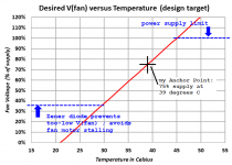 Figure_2.png35.6 KB · Views: 2,297
 -
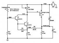 Figure_3.png13.3 KB · Views: 2,213
 -
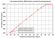 Figure_4.png24 KB · Views: 2,267
 -
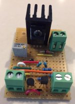 Figure_5.JPG31.6 KB · Views: 1,812
 -
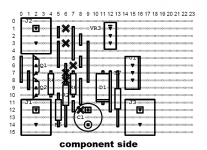 Figure_6.png62.8 KB · Views: 1,121
 -
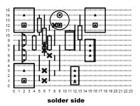 Figure_7.png56.6 KB · Views: 933
 -
Thermal_Fan_24V_schema_in_LTSPICE.asc2.6 KB · Views: 341

Nice. Simple, clean, elegant. Thanks for posting it.
In the process of estimating what fraction of the BOM the trimpot represented, I ran into some difficulty identifying the MOSFET you used. I believe that it was intended to be FQPF11P06, but was entered as FPQF11P06. My apologies if I have just foiled an attempt to discourage reverse-engineering, or a subtle goad to encourage readers to select their own PMOS device.
In the process of estimating what fraction of the BOM the trimpot represented, I ran into some difficulty identifying the MOSFET you used. I believe that it was intended to be FQPF11P06, but was entered as FPQF11P06. My apologies if I have just foiled an attempt to discourage reverse-engineering, or a subtle goad to encourage readers to select their own PMOS device.
Hi thanks for the catch! Just a simple typo, nothing sinister. The device I used, and whose part number I failed to correctly type, was
FQPF11P06 ON Semiconductor / Fairchild | Mouser
FQPF11P06 ON Semiconductor | Discrete Semiconductor Products | DigiKey
Its datasheet is attached below. I like the fact that it is in a fully insulated TO-220FP "full pack" package, and requires no insulator between MOSFET and heatsink.
To make things even more confusing, LTSPICE ships with a .MODEL of that transistor (suffix 11P06) but in a different package, thus a different part number. But diyAudio members are shrewd, and resourceful, as you have just demonstrated!
_
Attachments
Very nice! Exactly what I was looking for 2 months ago. As an aside, it might be better targeting 12v instead of 24v. It's easy (albeit inefficient) to drop to 12v with a regulator regardless of what the supply voltage is, and going to 12v opens up the number of fan choices 100 fold. Personally, I recommend as big of a fan turning as slowly as possible to reduce noise - 120 or 140mm diameter if space is available. Also, bearing type and orientation should be taken into account - some fans don't like being horizontal and some bearing types are noisier than others. My favorite brand is Noctua - designed for amazingly low noise and vibration.
An idea only: LM35 is a linear thermometer low cost and internally linearized with an output of 10mV/°C. Then, with one of them, (Or more with the outputs adequately weighted) actin at the output of a comparator (LM311) driving a MOS is also factible. A pot let you adjust the on/off temp or a window comparator can give you a flexible hysteresis.
Some time ago I did my previous idea to replace a mechanical thermostat in a thermostatic bath for industrial cleaning. 3 LM35's put in different zones, with their outputs added and divided by 3 give a mean of the bath temperature using a OPAMP. Then, comparing the output with a window comparator with around 5°C of hysteresis, I switched on or off the heater using a TRIAC. No transformer, capacitor (Capacitive reactance) to give power to the small controller. So simple that the owner after wanted to modify the same way his other baths. I job repairing industrial equipment in a small company in Buenos Aires.
I use LM35+LM2903+2pcs of swithcing bjts to drive a the cooling fan, with 2 speed. Linear solution available from Crest Audio schematics.
Sajti
Sajti
Nice analog speed controller.
However, the aerodynamic wind noise from a standard DC non-PWM fan is quite audible. Check the dB noise levels compared to a CFD optimized and purpose built *silent* (11dBA) PWM fan from Noctua, and it may turn out that trying to go non PWM in an effort to reduce electrical noise is not the core problem. The electrical noise from a PWM fan is easy to filter out with a CLC between the drive unit and the power. A ready to use commercial PWM controller with temp sensor, alarm, variable temp setpoints for speed up etc is $3. This and the Noctua PWM fan is how I cool my 150w dissipation per MOSFET Class A amp. The aero noise of a fan, no matter how quiet the electrical drive is, is the limiting factor if audible noise is the main concern.
For example:
https://www.ebay.com/p/12v-PWM-PC-C...d-Controller-Module-High-temp-Alarm/552854982
Last edited:
The Noctua DC fans are also similarly quiet, however the turn-down ratios of the native PWM models are usually much better than the straight DC ones.
The noise issue turning down some standard fans comes from the motor design. The motors are generally commutated using a simple direct hall-trigger mechanism, and in this case they produce a torque impulse that becomes increasingly obvious as the rotation speed drops. Fans that have powerful motors tend to suffer the most. With Noctua fans and some other noise optimised types, they use a combination of techniques to make sure the vibrations arising from the commutation is minimised. Similarly the Sunon maglev motor is an intrinsically quiet design, however the Sunon range are designed for extreme turn-down (like 400 through 6000 RPM on an 80mm frame) and don't use the extra high inertia rotor like Noctua do.
But I guess the motivation comes from whether you are able to sleep at night knowing there are current impulses and high voltage edge rates inside your pure audio system or not.
Last edited:
Why don't you use 12V fans a standard in PC boxes ?
I use large ones and simply wire them on 5V, for quiet PCs. There is no need for a hurricane inside, a gentle breeze is enough to remove hot spots at the mother board and graphic card. There is thermal shut down, but I have never seen it trip.
I use large ones and simply wire them on 5V, for quiet PCs. There is no need for a hurricane inside, a gentle breeze is enough to remove hot spots at the mother board and graphic card. There is thermal shut down, but I have never seen it trip.
It's not surprising to hear that some people don't object to having a PWM controller inside their audio equipment. Here is one example from last year.
However there are people who categorically refuse to even consider it. For those folks, all-analog is the only acceptable approach. Everyone acknowledges that all-analog has cost and performance drawbacks compared to PWM. That's why PWM fan controllers outnumber all-analog fan controllers by at least 100-to-1 in the field. But some people in some applications, won't use it. Not now, not ever. And thus was born this little 3-transistor circuit. I'm sure the clever folks on this site have already discovered how to shave it down to a 2-transistor circuit if desired. That would be fun, despite the minimal (~ $0.03) savings.
Noctua fans are indeed delightfully quiet, although their price seems a bit steep. They're available in both 4-pin (PWM only) and 3-pin (PWM or analog) versions. If you wanted to use Noctua 12V fans while simultaneously insisting upon an all-analog controller, in a First Watt amp running from a standard First Watt 23V supply, your options include: (a) use a 24V all-analog controller and simply connect two Noctua fans in series; (b) obtain a 12V all-analog fan controller and power it from a 12V regulator; (c) draw up a new and different design target Volts-vs-Temp curve, similar to "Figure 2" in post 1 above, with your new desired slope and Anchor Point, but which tops out at 50% instead of 100%. Then tweak component values until you get that design target curve; (d) and more.
I have a feeling that tweakers and optimizers might actually prefer a fan whose feedback control system is: the human user. Simply provide a knob labeled "fan speed", from 0% to 100%, which the user controls by hand. Also display the temperature at the sensor (thermistor, diode, IC, whatever). Then let the user decide what fan loudness he prefers and what internal temperature he can tolerate, right now. This may change depending on what music is playing right now, whether it's summer or winter right now, whether the ambient is quiet or noisy right now, whether the volume control is high or low right now, and so forth. Let the human tweak and optimize it as much or as little as he wishes, as often as he likes.
Question: Would a 1uF capacitor in parallel to the thermistor serve the purpose of "kick-starting" the spin of the fan at 'power-up'?
Once the blades are in motion, the "keep-a-turning" voltage would be probably even some 0,5V ... or maybe even 1V lower. Maybe then I could replace the 15V Zener with a 16V, or maybe even 17V one?
Once the blades are in motion, the "keep-a-turning" voltage would be probably even some 0,5V ... or maybe even 1V lower. Maybe then I could replace the 15V Zener with a 16V, or maybe even 17V one?
Last edited:
Sounds quite plausible; try it and find out whether it does what you want. I would have imagined you might choose the new capacitor C such that (R2 * C) >= 1 second.
True. 10uF should not be to big a form factor. It does not need to be a foil MKP or MKT in this application?Sounds quite plausible; try it and find out whether it does what you want. I would have imagined you might choose the new capacitor C such that (R2 * C) >= 1 second.
Could also be electrolytic, yes?
The leakage current of the elko - issue or not an issue?
Assume your heat sinks are designed such that they will take full dissipation without forced cooling.
Then all you gain by adding a cooling fan on the inside is to lower the temperature somewhat.
That is of course not a bad thing, but many circuits will have a different DC set point at say 30°C as opposed to 50°C.
If you decide that you want to have a smaller heat sink with forced cooling, then you need to blow at the fins.
i.e. the fins have to be facing inwards with fan inside the enclosure.
But it also means that when the fan is not working, the heat sinks themselves will not suffice passively.
If you wish to have the best possible thermal stability and compactness, then you should consider water-cooling.
It is also absolutely noise free if you just use tap water.
But of course, you might just want to do this for fun. 😉
Cheers,
Patrick
Yes. The Heatsinks are sized capable to handle the thermal load as is. With no forced cooling. This fan excersize I would make for fun. And or maybe for a bit of optional overvolting of he standard class A supply rails. Fan would keep the insides cooler. Hopefully prolonging the life of electrolytics a bit and providing for a bit of some extra comfort for the opt transistors. A nice to have, but not a need to have.Assume your heat sinks are designed such that they will take full dissipation without forced cooling.
Then all you gain by adding a cooling fan on the inside is to lower the temperature somewhat.
That is of course not a bad thing, but many circuits will have a different DC set point at say 30°C as opposed to 50°C.
If you decide that you want to have a smaller heat sink with forced cooling, then you need to blow at the fins.
i.e. the fins have to be facing inwards with fan inside the enclosure.
But it also means that when the fan is not working, the heat sinks themselves will not suffice passively.
If you wish to have the best possible thermal stability and compactness, then you should consider water-cooling.
It is also absolutely noise free if you just use tap water.
But of course, you might just want to do this for fun. 😉
Cheers,
Patrick
Last edited:
Someone bumped... jostled a thought....
At least as-of a couple years ago, the fan controller in a Subaru (and I assume most cars) was still a tapped resistor. Wind some fence-wire around a Sharpie and nail it to a phenolic board... that's about it. (Actually several sections; and in recent models a troublesome "overheat cut-out".)
Do car heater blowers outnumber desktop PC fan controllers? I dunno.
Obviously passive resistance "add heat". This is bad for amps, good for car-heat, bad for car-cooling. The car being usually an explosion engine, nobody is over-worried about "PWM trash" (as long as it does not confuse the ECU). I suspect factory inertia and sunk costs have much to do with why cars have passive resistor motor speed control. And some more-efficient cars may already have gone over to PWM to save several Watts (twice when cooling).
.....PWM fan controllers outnumber all-analog fan controllers by at least 100-to-1 in the field......
At least as-of a couple years ago, the fan controller in a Subaru (and I assume most cars) was still a tapped resistor. Wind some fence-wire around a Sharpie and nail it to a phenolic board... that's about it. (Actually several sections; and in recent models a troublesome "overheat cut-out".)
Do car heater blowers outnumber desktop PC fan controllers? I dunno.
Obviously passive resistance "add heat". This is bad for amps, good for car-heat, bad for car-cooling. The car being usually an explosion engine, nobody is over-worried about "PWM trash" (as long as it does not confuse the ECU). I suspect factory inertia and sunk costs have much to do with why cars have passive resistor motor speed control. And some more-efficient cars may already have gone over to PWM to save several Watts (twice when cooling).
Cold air is denser and in houses densest at floor level. With vertical fan heat sinks a chimney structure should accelerate the rise of heated air over an extended length. It should be possible to move air more by convection using a venturi approach with a chimney heat sink structure.
- Home
- Amplifiers
- Solid State
- Fan inside audio chassis: variable speed, temperature controlled, analog - No PWM