I have a 5V 2A class 2 wall wart. I carefully opened it up and there is a transformer followed by a full wave bridge and then 2 5600 microfarad 10V caps in parallel. All on a small PC board.
I would like to convert it to a regulated power supply. It seems all I need to do is remove the 2 large caps and replace one of them with a .33 microfarad cap, then in place of the other cap, put a L78S05C with the input and ground legs soldered where the other cap was, clip a heat sink on the TO-220 device, and then move the 5V output lead from the PC board to the third output leg of the L78S05C device. Finally, solder a .1 microfarad cap between the output leg and ground. Then glue the wall wart case back on. Or should I leave one of the 5600 microfarad caps on the board to provide some filtering? (Need to remove the other one to get space for the L78S05C)
Is it just that easy to convert an unregulated 5V wall wart to a regulated 5V linear power supply?
I am trying to use this to power a Wiim Pro + and replace the cheap switching power supply with a linear power supply. The requirement is 5V 1.5A and the input is a USB C connector. I tried plugging the 5V 2A class 2 to power it via an adapter from the 5.1mm plug to USB C but it wouldnt power up. Thinking the unregulated wall wart didnt provide the correct V. Any advice would help. There are a lot of small audio devices that could benefit from a better power supply, but didnt want to spend a whole lot of money on them. This seems a pretty straightforward and cheap solution.
Doubtful there will be enough excess DC voltage left (if any) to drop across the 7805.
You definitely would need a large input capacitor, otherwise the regulator would drop out twice each cycle.
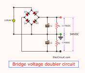
You could make a voltage doubler, which then feeds the 7805, but probably this transformer is inadequate for that.
You definitely would need a large input capacitor, otherwise the regulator would drop out twice each cycle.
You could make a voltage doubler, which then feeds the 7805, but probably this transformer is inadequate for that.

I see what you mean. Need min 7V for the L78S to work and 8V is preferable. Hard to find a class 2 8V 2A wall wart, but there are quite a few 7V 1.75A wall warts. Lots more 6V 2A wall warts, but that seems iffy, the open circuit voltage is probably over 7V, but under load may drop. It also depends on the actual wall wart, so asking if a 6V wall wart would work doesnt make sense. I may have to try a 7V wall wart and measure it under load and see what the voltage is.
That one needs 2 volts higher on the input than the output voltage is. Maybe there is a low dropout (LDO) model available that could work there.Doubtful there will be enough excess DC voltage left (if any) to drop across the 7805.
You definitely would need a large input capacitor, otherwise the regulator would drop out twice each cycle.
You could make a voltage doubler, which then feeds the 7805, but probably this transformer is inadequate for that.
Short answer: it won't work with such a low voltage supply.
Yes, you will probably measure 6 or 7V *unloaded ", that's why it is an unregulated supply, they guarantee 5V at full output... in which case there is zero extra voltage to work with.
Actually your current "cheap SMPS" is way better than that, go figure.
And if you Insist on a non switching one, ok, you can do that too but it will be way larger, heavier and more expensive.
Your choice 🤷
I am trying to avoid the noise of a SMPS. So far, I found that Apple 5V SMPS are pretty decent in terms of noise.
I am intrigued by this LDO: Rohm BA50DD0T It has .3 - .5V drop out, so it can run at 5.5V So even if there is AC line variation, a 6V input should work.
Since the availabiliy of a class 2 6V 2.5A wall wart is plentiful, I think I will try this LDO regulator with this 6V wall wart. yes, it is way larger, heavier but I am trying to alter my own. There are quite a few audio devices powered by cheap wall warts so I wanted to improve on these for not too much more money. $10 for a wall wart, $5 for the regulator and caps sure beats the $60-$100 for a linear power supply.
Question: The circuit asks for a capacitor .33microfarads between the input and ground. Can I skip this? Since the wall wart, after the full wave bridge already has a 5600 microfarad cap for filtering, it seems that an additional .33 microf cap is unneccesary. The antioscillation cap on the output end seems important. Looks to need a few ohm ESR cap to be stable.
I dug out a couple of schematics a few weeks ago, so if they'll help:You could make a voltage doubler,
Easy to test, and certainly enough voltage for the 7805 then!
Attachments
Edit: Referring to post #9
A low-ESR ceramic input cap (0.33) should be placed as close as possible to the IC (<1cm) regardless of the power supply smoothing caps.
The output cap needs to be between about 1-7 ohm ESR for stability.
Also make sure you have a bypass diode from the output to input, otherwise at power off the output cap will try to back drive the IC and damage it.
1 to 7 ohms would be extremely high for a capacitor's ESR. I'd deem such a capacitor defective. There are snubbers that have a cap and series resistor in the same package. The resistor dissipates the unwanted noise conducted to it by the capacitor as heat. The diode preventing backward current flow through a regulator upon turn-off is a good idea.
I am going to experiment a bit. Got a 5V, 6V and 7V class 2 wall wart, all about 2A. (Couldnt find a 8V 2A wall wart). Will use a BA50 LDO regulator and see what happens. Due to the tight space inside the wall wart, will replace the 2 10V 5600 microfarad caps with a single 10V 10000 microfarad cap and use the space for the BA50. (A 16V is just too large in diameter) A new single 10V 10000 µF cap is about the same size now as the existing 5600 µF cap. Will add the 2 small caps on the input and output side as people & application note suggests. I am hoping that it can fit inside the wall wart. I got ones that are large so there is more room.
One question though, "Also make sure you have a bypass diode from the output to input, otherwise at power off the output cap will try to back drive the IC and damage it."
I see in the application note for the BA50 that it suggests the bypass diode. Would you know what diode will work? e.g. specs? Thanks
This will be fun. I haven't seen anyone else trying this out on the web. If one of these works, it would be nice to be able to measure the noise level and compare to a SMPS.
- Home
- Amplifiers
- Power Supplies
- convert wall wart to regulated power supply